Download to read offline
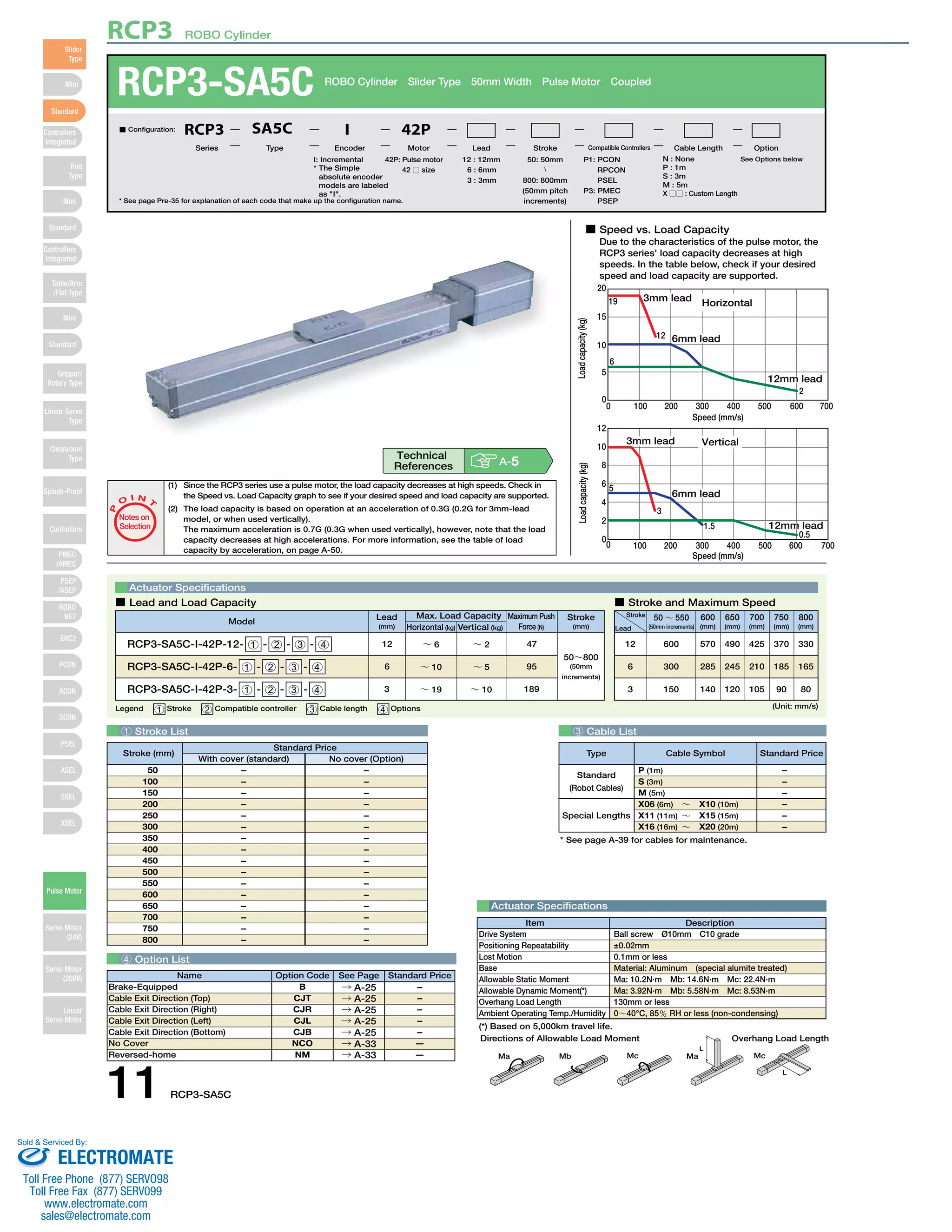
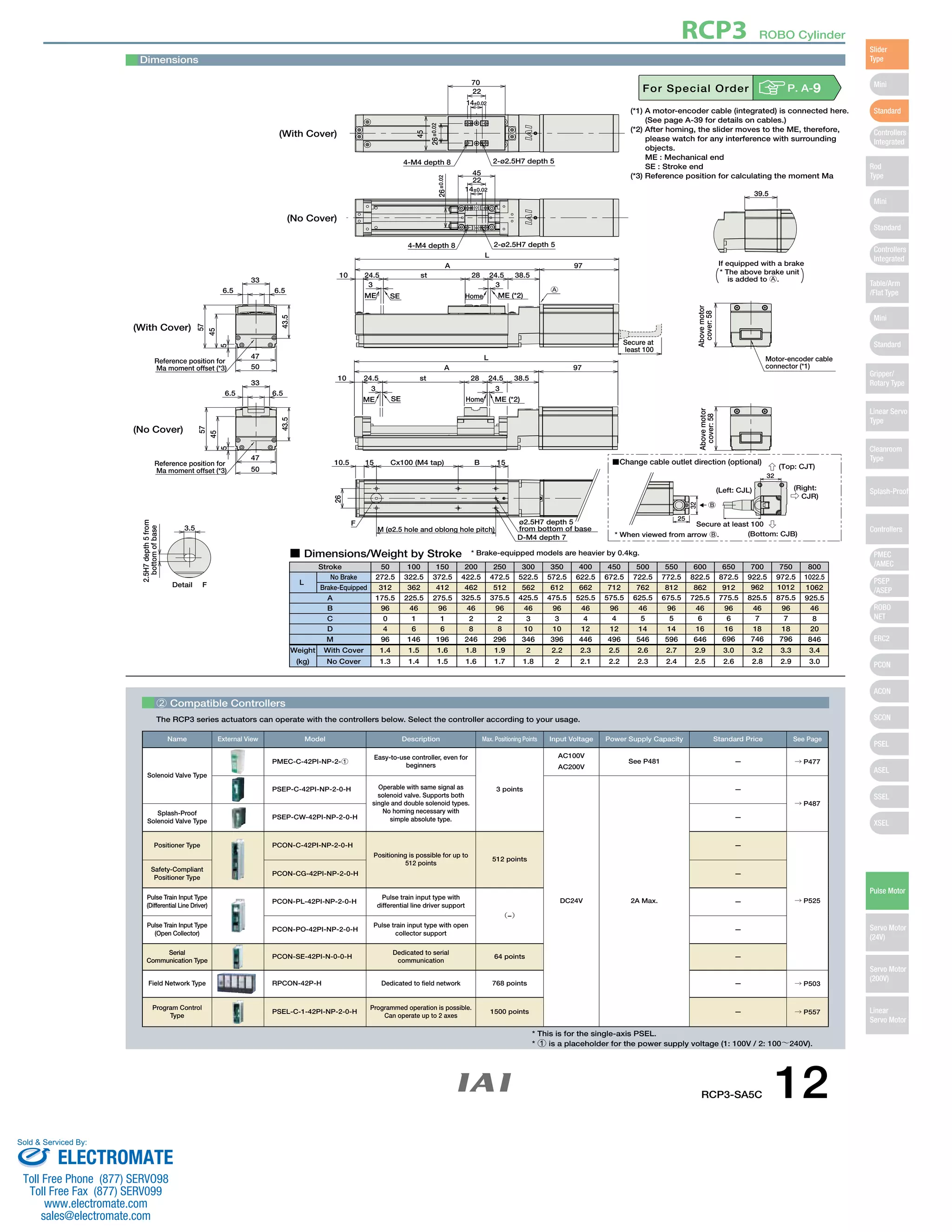

(1) The load capacity of the RCP3 series actuator decreases at higher speeds due to its pulse motor. Users should check the speed vs. load capacity graph to ensure their desired speed and load are supported. (2) Load capacity also depends on acceleration, with lower capacities at higher accelerations. The document provides tables of load capacity by acceleration. (3) The document provides specifications, dimensions, weight and price for RCP3 series actuators with various strokes and configuration options. Compatible controllers that can operate the actuators are also listed.


