Download to read offline
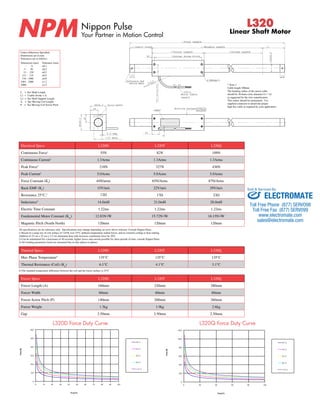

This document provides specifications for the Nippon Pulse L320 series linear shaft motors in three models: L320D, L320T, and L320Q. It includes details on dimensions, performance characteristics like force and current ratings, electrical properties, thermal properties, and part numbering conventions. Stroke lengths between 100-3650mm are available.


![Azzuro[2][1]](https://cdn.slidesharecdn.com/ss_thumbnails/azzuro21-140222044540-phpapp01-thumbnail.jpg?width=640&height=640&fit=bounds)


