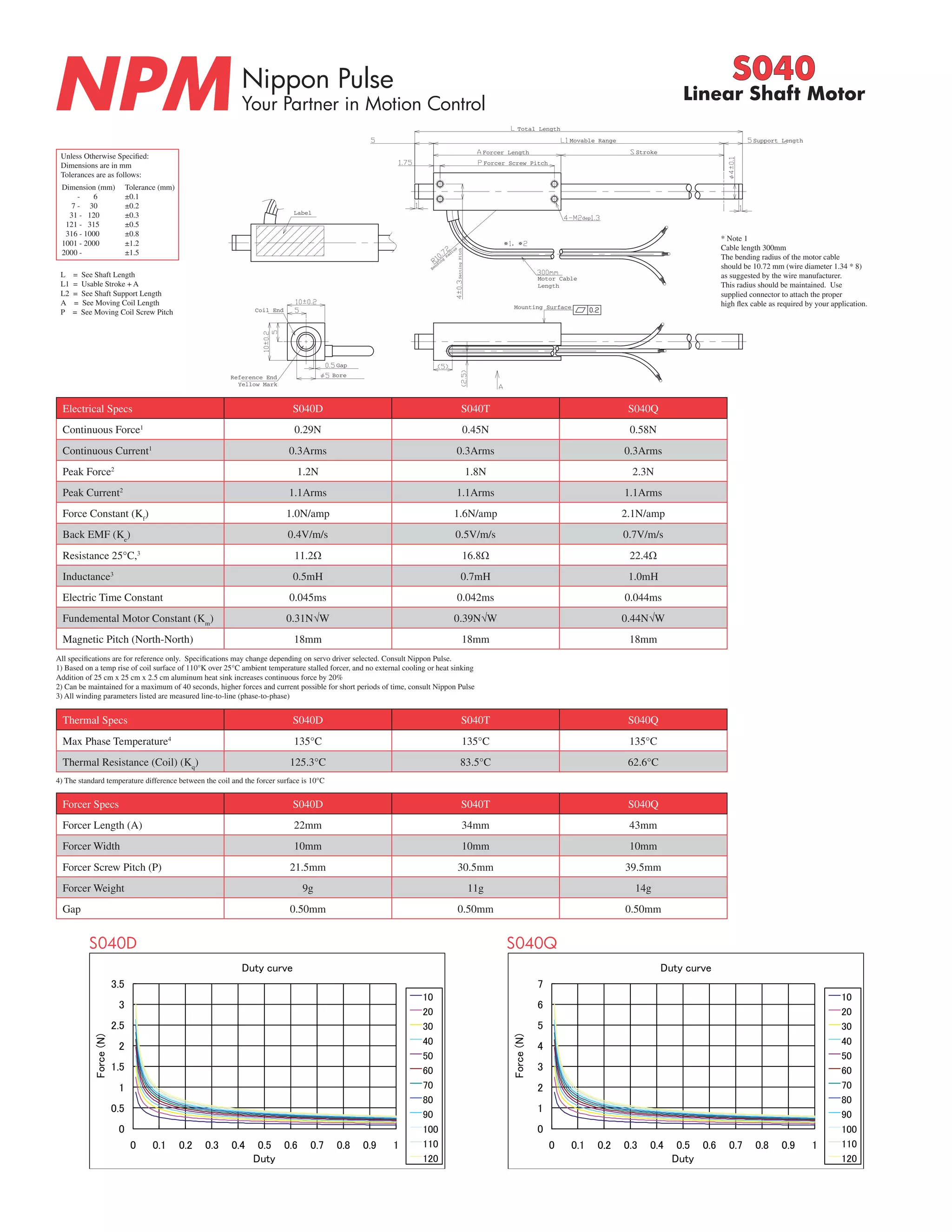
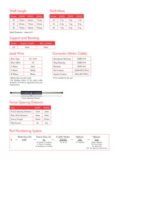
The document provides specifications for Nippon Pulse linear shaft motors models S040D, S040T, and S040Q. It includes details on dimensions, electrical specifications like force, current and resistance, thermal specifications, force specifications, duty curves, shaft lengths, masses, lead wire and connector information. Tolerances for dimensions are provided in a table.
1. Nippon Pulse
Your Partner in Motion Control NPM S040
Linear Shaft Motor
Coil End
Coil End
Reference End Bore
Reference End Bore
Label
Gap
Motor Cable
Length
Mounting Surface
Setting Pitch
Bending Radius
dep
Total Length
Motor Cable
Length
Movable Range
Forcer Length
Forcer Screw Pitch
Stroke
Support Length
Yellow Mark
Label
Gap
Mounting Surface
Setting Pitch Bending Radius
Yellow Mark
Unless Otherwise Specified:
Dimensions are in mm
Tolerances are as follows:
Dimension (mm)
- 6
7 - 30
31 - 120
121 - 315
316 - 1000
1001 - 2000
2000 -
Tolerance (mm)
±0.1
±0.2
±0.3
±0.5
±0.8
±1.2
±1.5
Electrical Specs S040D S040T S040Q
Continuous Force1 0.29N 0.45N 0.58N
Continuous Current1 0.3Arms 0.3Arms 0.3Arms
Peak Force2 1.2N 1.8N 2.3N
Peak Current2 1.1Arms 1.1Arms 1.1Arms
Force Constant (Kf) 1.0N/amp 1.6N/amp 2.1N/amp
Back EMF (Ke) 0.4V/m/s 0.5V/m/s 0.7V/m/s
Resistance 25°C,3 11.2Ω 16.8Ω 22.4Ω
Inductance3 0.5mH 0.7mH 1.0mH
Electric Time Constant 0.045ms 0.042ms 0.044ms
Fundemental Motor Constant (Km) 0.31N√W 0.39N√W 0.44N√W
Magnetic Pitch (North-North) 18mm 18mm 18mm
All specifications are for reference only. Specifications may change depending on servo driver selected. Consult Nippon Pulse.
1) Based on a temp rise of coil surface of 110°K over 25°C ambient temperature stalled forcer, and no external cooling or heat sinking
Addition of 25 cm x 25 cm x 2.5 cm aluminum heat sink increases continuous force by 20%
2) Can be maintained for a maximum of 40 seconds, higher forces and current possible for short periods of time, consult Nippon Pulse
3) All winding parameters listed are measured line-to-line (phase-to-phase)
Thermal Specs S040D S040T S040Q
Max Phase Temperature4 135°C 135°C 135°C
Thermal Resistance (Coil) (Kq) 125.3°C 83.5°C 62.6°C
4) The standard temperature difference between the coil and the forcer surface is 10°C
Forcer Specs S040D S040T S040Q
Forcer Length (A) 22mm 34mm 43mm
Forcer Width 10mm 10mm 10mm
Forcer Screw Pitch (P) 21.5mm 30.5mm 39.5mm
Forcer Weight 9g 11g 14g
Gap 0.50mm 0.50mm 0.50mm
3.5
3
2.5
2
1.5
1
0.5
0
Duty curve
0 0.1 0.2 0.3 0.4 0.5 0.6 0.7 0.8 0.9 1
Force (N)
Duty
10
20
30
40
50
60
70
80
90
100
110
120
7
6
5
4
3
2
1
0
Duty curve
0 0.1 0.2 0.3 0.4 0.5 0.6 0.7 0.8 0.9 1
Force (N)
Duty
10
20
30
40
50
60
70
80
90
100
110
120
S040D S040Q
* Note 1
Cable length 300mm
The bending radius of the motor cable
should be 10.72 mm (wire diameter 1.34 * 8)
as suggested by the wire manufacturer.
This radius should be maintained. Use
supplied connector to attach the proper
high flex cable as required by your application.
L = See Shaft Length
L1 = Usable Stroke + A
L2 = See Shaft Support Length
A = See Moving Coil Length
P = See Moving Coil Screw Pitch
2. Shaft Length
Stroke S040D S040T S040Q
20 55mm 64mm 73mm
30 65mm 74mm 83mm
40 75mm 84mm 93mm
Shaft Mass
Stroke S040D S040T S040Q
20 5.5g 6.4g 7.3g
30 6.5g 7.4g 8.3g
40 7.5g 8.4g 9.3g
Shaft Diameter - 4mm ±0.1
Support and Bending
Stroke Support Length Max. bending
All 5mm 0mm
Lead Wire
Wire Type UL 1430
Wire AWG 28
U Phase Red
V Phase White
W Phase Black
-300mm lead wire bare leads
-The bending radius of the motor cable
should be 10.72mm as suggested by the wire
manufacturer.
Connector (Motor Cable)
Receptacle Housing XMR-03V
Plug Housing XMP-03V
Retainer XMS-03V
Pin Contact SXM-001T-P0.6
Socket Contact SXA-001T-P0.6
-To be installed by the user
Forcer Spacing Distance
Spec S040T S040Q
Forcer Spacing Distance 2mm 2mm
Pole (N/S) Distance 9mm 9mm
Forcer Length 34mm 43mm
Flip Forcers No Yes
Shaft Size (D) Forcer Size (A) Usable Stroke Options Options
S — 040 — X — XXXX — XX — XX
D: Double (2) windings
T: Triple (3) windings
Q: Quadruple (4) windings
20, 30, 40 ST: Standard Blank: Standard
FO: Forcer Only
SO: Shaft Only
XX: Two digit for custom motor
Part Numbering System