Download to read offline
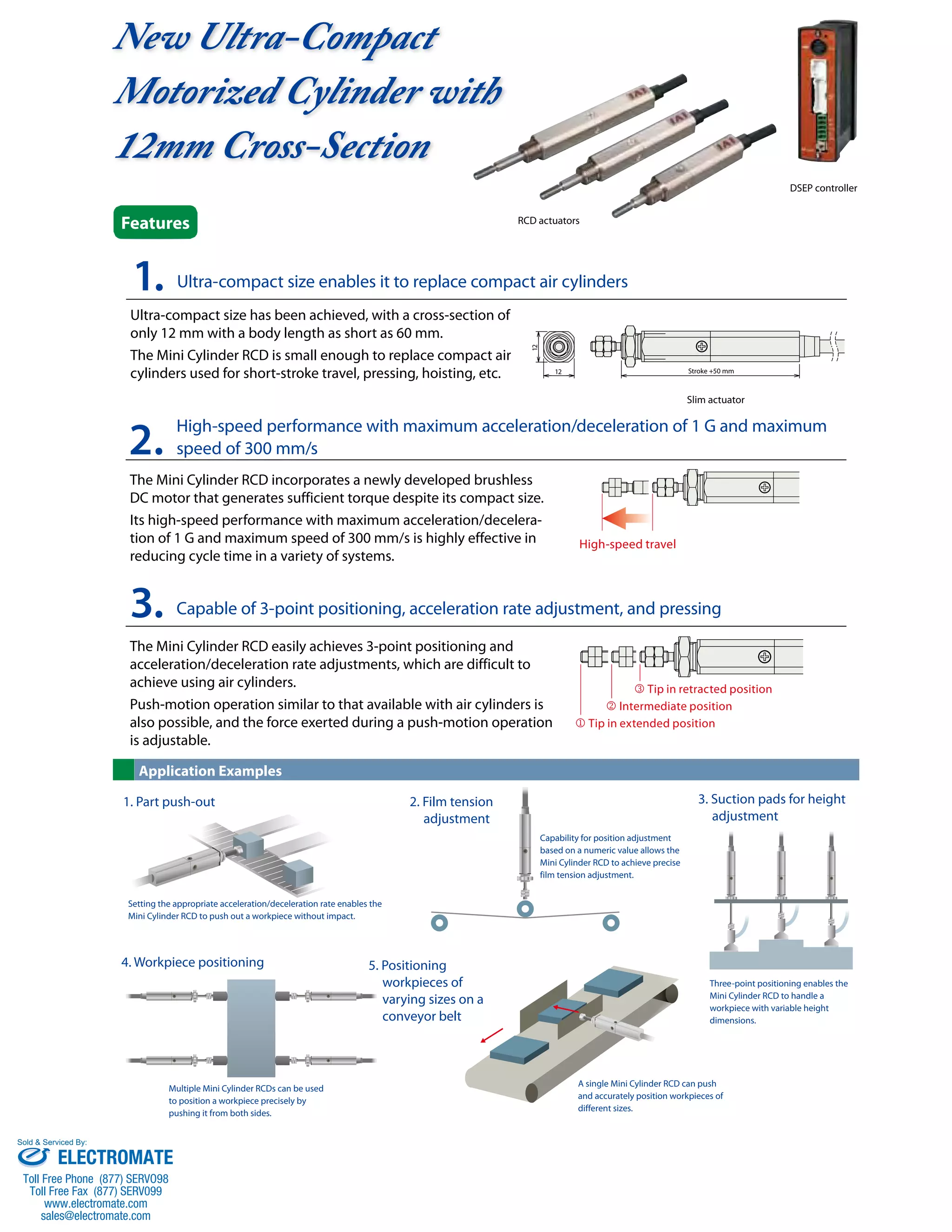

This document summarizes an ultra-compact motorized cylinder called the Mini Cylinder RCD. It has a cross section of only 12mm and can achieve high speeds of up to 300mm/s. It is capable of 3-point positioning and adjustable acceleration/deceleration rates. Its compact size allows it to replace air cylinders in applications requiring short stroke travel or precise positioning of parts.


![Vibe Coding vs. Spec-Driven Development [Free Meetup]](https://cdn.slidesharecdn.com/ss_thumbnails/vibecodingvsspecdrivendevelopment-251209105622-43f455e7-thumbnail.jpg?width=640&height=640&fit=bounds)


