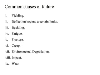
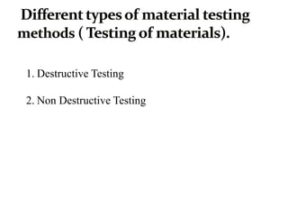
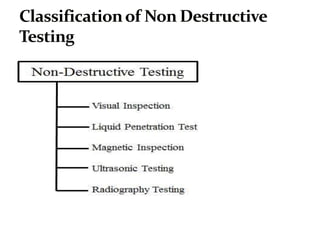
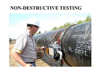
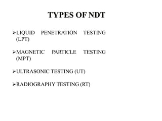
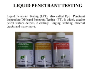
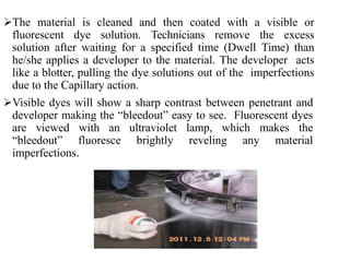
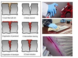
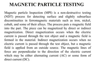
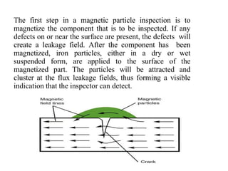
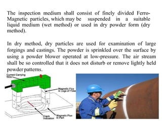
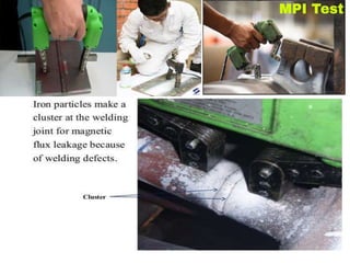
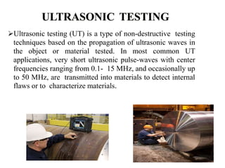
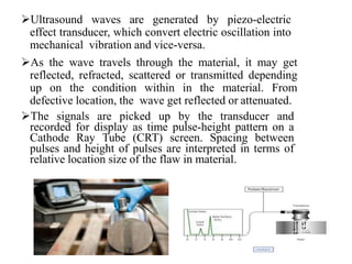
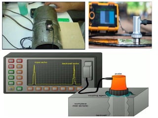
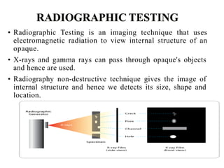
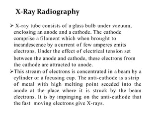
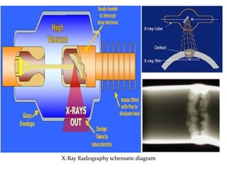
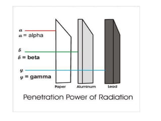
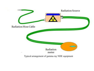
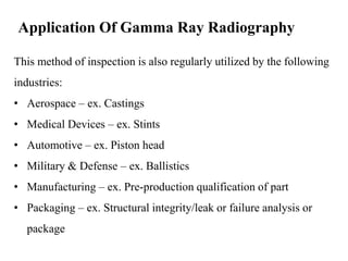
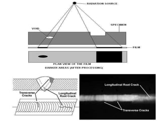
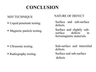
KAILASH SINGH SIJWALI
• Fracture is a form of failure where the material separates in
pieces due to stress, at temperatures below the melting point.
• The fracture is termed as ductile or brittle depending on
whether the elongation is large or small.
• Steps in fracture (response to stress):
crack formation
crack propagation.
PROPERTIES DUCTILE BRITTLE
DEFORMATION EXTENSIVE LITTLE
CRACK
PROPAGATION
SLOW FAST
TYPES OF
MATERIAL
MOSTLY METALS CERAMICS, ICE,
COLD METALS
WARNING PERMANENT
ELONGATION
NONE
STRAIN ENERGY HIGHER LOWER
FRACTURED
SURFACE
ROUGH SMOOTH
NECKING YES NO
i. Yielding.
ii. Deflection beyond a certain limits.
iii. Buckling.
iv. Fatigue.
v. Fracture.
vi. Creep.
vii. Environmental Degradation.
viii. Impact.
ix. Wear.
Mode I fracture
Mode II fracture
Mode III fracture
1. Destructive Testing
2. Non Destructive Testing
Nondestructive testing (NDT) is the process of inspecting, testing, or
evaluating materials, components or assemblies for discontinuities, or
differences in characteristics without destroying the serviceability of
the part or system. In other words, when the inspection or test is
completed the part can still be used.
LIQUID PENETRATION TESTING
(LPT)
MAGNETIC PARTICLE TESTING
(MPT)
ULTRASONIC TESTING (UT)
RADIOGRAPHY TESTING (RT)
Liquid Penetrant Testing (LPT), also called Dye Penetrant
Inspection (DPI) and Penetrant Testing (PT), is widely used to
detect surface defects in castings, forging, welding, material
cracks and many more.
The material is cleaned and then coated with a visible or
fluorescent dye solution. Technicians remove the excess
solution after waiting for a specified time (Dwell Time) than
he/she applies a developer to the material. The developer acts
like a blotter, pulling the dye solutions out of the imperfections
due to the Capillary action.
Visible dyes will show a sharp contrast between penetrant and
developer making the “bleedout” easy to see. Fluorescent dyes
are viewed with an ultraviolet lamp, which makes the
“bleedout” fluoresce brightly reveling any material
imperfections.
Magnetic particle Inspection (MPI) is a non-destructive testing
(NDT) process for detecting surface and slightly subsurface
discontinuities in ferromagnetic materials such as iron, nickel,
cobalt, and some of their alloys. The process puts a magnetic field
into the part. The piece can be magnetized by direct or indirect
magnetization. Direct magnetization occurs when the electric
current is passed through the test object and a magnetic field is
formed in the material. Indirect magnetization occurs when no
electric current is passed through the test object, but a magnetic
field is applied from an outside source. The magnetic lines of
force are perpendicular to the direction of the electric current
which may be either alternating current (AC) or some form of
direct current (DC).
The first step in a magnetic particle inspection is to
magnetize the component that is to be inspected. If any
defects on or near the surface are present, the defects will
create a leakage field. After the component has been
magnetized, iron particles, either in a dry or wet
suspended form, are applied to the surface of the
magnetized part. The particles will be attracted and
cluster at the flux leakage fields, thus forming a visible
indication that the inspector can detect.
The inspection medium shall consist of finely divided Ferro-
Magnetic particles, which may be suspended in a suitable
liquid medium (wet method) or used in dry powder form (dry
method).
In dry method, dry particles are used for examination of large
forgings and castings. The powder is sprinkled over the surface by
using a powder blower operated at low-pressure. The air stream
shall be so controlled that it does not disturb or remove lightly held
powder patterns.
Ultrasonic testing (UT) is a type of non-destructive testing
techniques based on the propagation of ultrasonic waves in
the object or material tested. In most common UT
applications, very short ultrasonic pulse-waves with center
frequencies ranging from 0.1- 15 MHz, and occasionally up
to 50 MHz, are transmitted into materials to detect internal
flaws or to characterize materials.
 The conversion of electrical pulses to mechanical vibrations
and the conversion of returned mechanical vibrations back
into electrical energy is the basis for ultrasonic testing. The
active element is the transducer as it converts the electrical
energy to mechanical vibrations, and vice versa. This
phenomena is known as piezoelectric effect.
In ultrasonic testing, ultrasound transducer connected to
a diagnostic machine is passed over the object being
inspected. The transducer is typically separated from the
test object by a couplant (such as oil) or by water, as in
immersion testing.
Ultrasound waves are generated by piezo-electric
effect transducer, which convert electric oscillation into
mechanical vibration and vice-versa.
As the wave travels through the material, it may get
reflected, refracted, scattered or transmitted depending
up on the condition within in the material. From
defective location, the wave get reflected or attenuated.
The signals are picked up by the transducer and
recorded for display as time pulse-height pattern on a
Cathode Ray Tube (CRT) screen. Spacing between
pulses and height of pulses are interpreted in terms of
relative location size of the flaw in material.
• Radiographic Testing is an imaging technique that uses
electromagnetic radiation to view internal structure of an
opaque.
• X-rays and gamma rays can pass through opaque's objects
and hence are used.
• Radiography non-destructive technique gives the image of
internal structure and hence we detects its size, shape and
location.
 X-ray tube consists of a glass bulb under vacuum,
enclosing an anode and a cathode. The cathode
comprise a filament which when brought to
incandescence by a current of few amperes emits
electrons. Under the effect of electrical tension set
between the anode and cathode, these electrons from
the cathode are attracted to anode.
This stream of electrons is concentrated in a beam by a
cylinder or a focusing cup. The anti-cathode is a strip
of metal with high melting point seceded into the
anode at the place where it is struck by the beam
electrons. It is by impinging on the anti-cathode that
the fast moving electrons give X-rays.
X-Ray Radiography
X-Ray Radiography schematic diagram
• The part is to inspected is placed between radiation source and
piece of radiation sensitive film.
• The radiation source can either be an X-ray machine or a
radioactive source (Ir-192, Co-60, or in rare cases Cs-137)
• The part will stop some of the radiation where thicker and more
dense areas will stop more of the radiation.
• The radiation that passes through the part will expose the film
and forms a shadowgraph of the part.
• No part preparation is required.
• Both surface and internal discontinuities can be detected.
• Significant variations in compositions can be detected.
• Wavelength of X-Ray can be changed and because of this one
can vary penetration power.
• It can used for inspecting hidden areas.
• Permanent test record is obtained.
• Hazardous to operate and other nearby personnel's.
• High degree of skill and experience required to operate.
• It require access to the component at least two sides.
• Gamma rays are produced by a radioisotope.
• A radioisotope has an unstable nuclei that does not have
enough binding energy to hold the nucleus together.
• The spontaneous breakdown of an atomic nucleus resulting in
the release of energy and matter is known as radioactive decay.
Typical arrangement of gamma ray NDE equipment
Application Of Gamma Ray Radiography
This method of inspection is also regularly utilized by the following
industries:
• Aerospace – ex. Castings
• Medical Devices – ex. Stints
• Automotive – ex. Piston head
• Military & Defense – ex. Ballistics
• Manufacturing – ex. Pre-production qualification of part
• Packaging – ex. Structural integrity/leak or failure analysis or
package
NDT TECHNIQUE
 Liquid penetrant testing.
 Magnetic particle testing.
 Ultrasonic testing.
 Radiography testing.
NATURE OF DEFECT
 Surface and sub-surface
defects.
 Surface and slightly sub-
surface defects in
ferromagnetic materials.
 Sub-surface and interstitial
defects.
 Surface and sub-surface
defects
CONCLUSION
THANK YOU!

Kailash ppt wit

  • 1.
  • 2.
    • Fracture isa form of failure where the material separates in pieces due to stress, at temperatures below the melting point. • The fracture is termed as ductile or brittle depending on whether the elongation is large or small. • Steps in fracture (response to stress): crack formation crack propagation.
  • 3.
    PROPERTIES DUCTILE BRITTLE DEFORMATIONEXTENSIVE LITTLE CRACK PROPAGATION SLOW FAST TYPES OF MATERIAL MOSTLY METALS CERAMICS, ICE, COLD METALS WARNING PERMANENT ELONGATION NONE STRAIN ENERGY HIGHER LOWER FRACTURED SURFACE ROUGH SMOOTH NECKING YES NO
  • 4.
    i. Yielding. ii. Deflectionbeyond a certain limits. iii. Buckling. iv. Fatigue. v. Fracture. vi. Creep. vii. Environmental Degradation. viii. Impact. ix. Wear.
  • 5.
    Mode I fracture ModeII fracture Mode III fracture
  • 6.
    1. Destructive Testing 2.Non Destructive Testing
  • 10.
    Nondestructive testing (NDT)is the process of inspecting, testing, or evaluating materials, components or assemblies for discontinuities, or differences in characteristics without destroying the serviceability of the part or system. In other words, when the inspection or test is completed the part can still be used.
  • 11.
    LIQUID PENETRATION TESTING (LPT) MAGNETICPARTICLE TESTING (MPT) ULTRASONIC TESTING (UT) RADIOGRAPHY TESTING (RT)
  • 12.
    Liquid Penetrant Testing(LPT), also called Dye Penetrant Inspection (DPI) and Penetrant Testing (PT), is widely used to detect surface defects in castings, forging, welding, material cracks and many more.
  • 13.
    The material iscleaned and then coated with a visible or fluorescent dye solution. Technicians remove the excess solution after waiting for a specified time (Dwell Time) than he/she applies a developer to the material. The developer acts like a blotter, pulling the dye solutions out of the imperfections due to the Capillary action. Visible dyes will show a sharp contrast between penetrant and developer making the “bleedout” easy to see. Fluorescent dyes are viewed with an ultraviolet lamp, which makes the “bleedout” fluoresce brightly reveling any material imperfections.
  • 15.
    Magnetic particle Inspection(MPI) is a non-destructive testing (NDT) process for detecting surface and slightly subsurface discontinuities in ferromagnetic materials such as iron, nickel, cobalt, and some of their alloys. The process puts a magnetic field into the part. The piece can be magnetized by direct or indirect magnetization. Direct magnetization occurs when the electric current is passed through the test object and a magnetic field is formed in the material. Indirect magnetization occurs when no electric current is passed through the test object, but a magnetic field is applied from an outside source. The magnetic lines of force are perpendicular to the direction of the electric current which may be either alternating current (AC) or some form of direct current (DC).
  • 16.
    The first stepin a magnetic particle inspection is to magnetize the component that is to be inspected. If any defects on or near the surface are present, the defects will create a leakage field. After the component has been magnetized, iron particles, either in a dry or wet suspended form, are applied to the surface of the magnetized part. The particles will be attracted and cluster at the flux leakage fields, thus forming a visible indication that the inspector can detect.
  • 17.
    The inspection mediumshall consist of finely divided Ferro- Magnetic particles, which may be suspended in a suitable liquid medium (wet method) or used in dry powder form (dry method). In dry method, dry particles are used for examination of large forgings and castings. The powder is sprinkled over the surface by using a powder blower operated at low-pressure. The air stream shall be so controlled that it does not disturb or remove lightly held powder patterns.
  • 19.
    Ultrasonic testing (UT)is a type of non-destructive testing techniques based on the propagation of ultrasonic waves in the object or material tested. In most common UT applications, very short ultrasonic pulse-waves with center frequencies ranging from 0.1- 15 MHz, and occasionally up to 50 MHz, are transmitted into materials to detect internal flaws or to characterize materials.
  • 20.
     The conversionof electrical pulses to mechanical vibrations and the conversion of returned mechanical vibrations back into electrical energy is the basis for ultrasonic testing. The active element is the transducer as it converts the electrical energy to mechanical vibrations, and vice versa. This phenomena is known as piezoelectric effect. In ultrasonic testing, ultrasound transducer connected to a diagnostic machine is passed over the object being inspected. The transducer is typically separated from the test object by a couplant (such as oil) or by water, as in immersion testing.
  • 21.
    Ultrasound waves aregenerated by piezo-electric effect transducer, which convert electric oscillation into mechanical vibration and vice-versa. As the wave travels through the material, it may get reflected, refracted, scattered or transmitted depending up on the condition within in the material. From defective location, the wave get reflected or attenuated. The signals are picked up by the transducer and recorded for display as time pulse-height pattern on a Cathode Ray Tube (CRT) screen. Spacing between pulses and height of pulses are interpreted in terms of relative location size of the flaw in material.
  • 23.
    • Radiographic Testingis an imaging technique that uses electromagnetic radiation to view internal structure of an opaque. • X-rays and gamma rays can pass through opaque's objects and hence are used. • Radiography non-destructive technique gives the image of internal structure and hence we detects its size, shape and location.
  • 24.
     X-ray tubeconsists of a glass bulb under vacuum, enclosing an anode and a cathode. The cathode comprise a filament which when brought to incandescence by a current of few amperes emits electrons. Under the effect of electrical tension set between the anode and cathode, these electrons from the cathode are attracted to anode. This stream of electrons is concentrated in a beam by a cylinder or a focusing cup. The anti-cathode is a strip of metal with high melting point seceded into the anode at the place where it is struck by the beam electrons. It is by impinging on the anti-cathode that the fast moving electrons give X-rays. X-Ray Radiography
  • 25.
  • 26.
    • The partis to inspected is placed between radiation source and piece of radiation sensitive film. • The radiation source can either be an X-ray machine or a radioactive source (Ir-192, Co-60, or in rare cases Cs-137) • The part will stop some of the radiation where thicker and more dense areas will stop more of the radiation. • The radiation that passes through the part will expose the film and forms a shadowgraph of the part.
  • 27.
    • No partpreparation is required. • Both surface and internal discontinuities can be detected. • Significant variations in compositions can be detected. • Wavelength of X-Ray can be changed and because of this one can vary penetration power. • It can used for inspecting hidden areas. • Permanent test record is obtained.
  • 28.
    • Hazardous tooperate and other nearby personnel's. • High degree of skill and experience required to operate. • It require access to the component at least two sides.
  • 29.
    • Gamma raysare produced by a radioisotope. • A radioisotope has an unstable nuclei that does not have enough binding energy to hold the nucleus together. • The spontaneous breakdown of an atomic nucleus resulting in the release of energy and matter is known as radioactive decay.
  • 31.
    Typical arrangement ofgamma ray NDE equipment
  • 32.
    Application Of GammaRay Radiography This method of inspection is also regularly utilized by the following industries: • Aerospace – ex. Castings • Medical Devices – ex. Stints • Automotive – ex. Piston head • Military & Defense – ex. Ballistics • Manufacturing – ex. Pre-production qualification of part • Packaging – ex. Structural integrity/leak or failure analysis or package
  • 34.
    NDT TECHNIQUE  Liquidpenetrant testing.  Magnetic particle testing.  Ultrasonic testing.  Radiography testing. NATURE OF DEFECT  Surface and sub-surface defects.  Surface and slightly sub- surface defects in ferromagnetic materials.  Sub-surface and interstitial defects.  Surface and sub-surface defects CONCLUSION
  • 35.