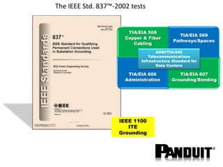
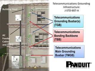
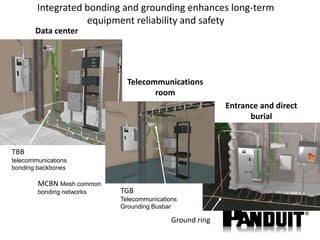
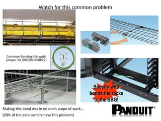
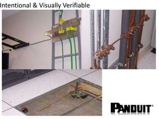
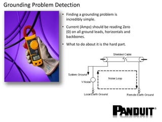
DPS
David Palmer-Stevens
Channel Enablement EMEA
Mobile +44 7703194479
Email gb-dps@panduit.com
Grounding and Bonding
Low cost mitigation of risk
5/6/2015
Webex series
1. Panduit is a credible partner
2. IT deployment Racks and Cabinets
3. Copper and Fibre solutions
4. PDU’s
5. Containment
6. Pathways
7. Rack Energy
8. DCIM positioning and capabilities
9. Grounding and Bonding
10.Pre-configured
5/6/2015
Grounding and Bonding
Objectives
Grounding and bonding
scope
Solution
www.panduit.com/comstor
webinar
Objective
Overview of Panduit capability
and motivate you to take a look
at the solutions
The Risks of Improper Grounding & Bonding
• Safety
– Shocks
– Fire hazards
• Lightning
– Insurance data: $500 million/year due to lightning
damage
• Equipment failure
– ESD (Electrostatic Discharge) responsible for 27-33% of
IT equipment failure
• The risk of electrical noise
– Noise degrades the electrical signal Ethernet response
is to retransmit
Electrostatic discharge (ESD)
• Electrostatic charges are generated when different
materials come into contact and are then
separated.”
• If you see or hear the ESD discharge it is a
minimum of 2,900V
• Here are some examples of voltages generated by
ESD events:
– Walking across carpet:
1,500 - 35,500 volts
– Picking up a plastic bag:
1,200 – 20,000 volts
– Crossing your legs:
300 volts
• Cables can acquire a charge during installation
when they are unreeled from a cable reel, or
dragged across a floor. There have also been
reports of cables developing their own charge from
moving air or from building occupants walking over
floor ducts.”
ESD Is greatly affected by
Relative Humidity > 30%
The IEEE Std. 837™-2002 tests
TIA/EIA 568
Copper & Fiber
Cabling
TIA/EIA 569
Pathways/Spaces
TIA/EIA 606
Administration
TIA/EIA 607
Grounding/Bonding
IEEE 1100
ITE
Grounding
ANSI/TIA-942
Telecommunications
Infrastructure Standard for
Data Centers
Telecommunications Grounding
Infrastructure
J-STD-607-A
Telecommunications
Main Grounding
Busbar (TMGB)
Telecommunications
Bonding Backbone
(TBB)
Telecommunications
Grounding Busbar(s)
(TGB)
AC
Feeder
Cables
and ACEG
Building Steel
AC
MAIN
AC
AC
Integrated bonding and grounding enhances long-term
equipment reliability and safety
Telecommunications
room
Data center
Entrance and direct
burial
TGB
Telecommunications
Grounding Busbar
MCBN Mesh common
bonding networks
TBB
telecommunications
bonding backbones
Ground ring
Watch for this common problem
Common Bonding Network
Jumper Kit (RGCBNJ660P22)
Making this bond was in no one’s scope of work...
(20% of the data centers have this problem)
Specify who
bonds the racks
to the SBG!
Grounding and Bonding equipment
Grounding standards compliance
for operability
Conductor to ground rod
Conductor to building steel
Conductor to rebar
Conductor to
grounding electrodes
Conductor to conductor
HTAP Crimping
• HTCT HTAPs require 12
tons of compression
• CT-2930/L is
recommended
• Can use other
manufacturers’ tools and
retain UL Listing/CSA
Certification
• Must use Panduit locator
dies
Patented
locating rib
guarantees full-
width crimp 1st
time, every
time!
HTCT HTAP
CD-930H-250 Locator Die
CT-2930/L
Supplemental bonding grid construction per TIA-607-B
Example supplemental bonding grid
Hinged U-bolt design allows for “no
look” installation—saving 67% of
installation time
Intentional & Visually Verifiable
The connector is then
bonded to the patch
panel
The system grounding
protection starts at the
jacks module with 360o
shielding
The patch panel is
bonded to the equipment
rack for protection
Finally, the entire
system is bonded to a
main bus bar located in
the floor
4
2
1
3
Bonding and Grounding for Shielded Cables
Implementing the equipment
grounding requirement
Bond equipment
with a jumper
when possible
Bonding screws have thread-
forming threads and serrations
under the head that remove the
paint off mounting flanges and
patch panels (RGTBSG-C)
Bonding cage nuts have
teeth that cut paint when
installed (CBN4K)
16
• UTP28SP8IN** 20cm/8in
• UTP28SP8IN**-48 Bulk pack
• Switch Port Replication
• No wire managers
TIA-942: “Wrist strap ports should be
attached to the rack…”
Grounding Problem Detection
• Finding a grounding problem is
incredibly simple.
• Current (Amps) should be reading Zero
(0) on all ground leads, horizontals and
backbones.
• What to do about it is the hard part.
Bond “one-end” or “both-ends” of a channel?
Same Ground Potential
5/6/2015
Panduit Documentation
www.panduit.com/comstorwebinar

Panduit EMEA SI Webinar 9

  • 1.
    DPS David Palmer-Stevens Channel EnablementEMEA Mobile +44 7703194479 Email gb-dps@panduit.com Grounding and Bonding Low cost mitigation of risk
  • 2.
    5/6/2015 Webex series 1. Panduitis a credible partner 2. IT deployment Racks and Cabinets 3. Copper and Fibre solutions 4. PDU’s 5. Containment 6. Pathways 7. Rack Energy 8. DCIM positioning and capabilities 9. Grounding and Bonding 10.Pre-configured
  • 3.
    5/6/2015 Grounding and Bonding Objectives Groundingand bonding scope Solution www.panduit.com/comstor webinar Objective Overview of Panduit capability and motivate you to take a look at the solutions
  • 4.
    The Risks ofImproper Grounding & Bonding • Safety – Shocks – Fire hazards • Lightning – Insurance data: $500 million/year due to lightning damage • Equipment failure – ESD (Electrostatic Discharge) responsible for 27-33% of IT equipment failure • The risk of electrical noise – Noise degrades the electrical signal Ethernet response is to retransmit
  • 5.
    Electrostatic discharge (ESD) •Electrostatic charges are generated when different materials come into contact and are then separated.” • If you see or hear the ESD discharge it is a minimum of 2,900V • Here are some examples of voltages generated by ESD events: – Walking across carpet: 1,500 - 35,500 volts – Picking up a plastic bag: 1,200 – 20,000 volts – Crossing your legs: 300 volts • Cables can acquire a charge during installation when they are unreeled from a cable reel, or dragged across a floor. There have also been reports of cables developing their own charge from moving air or from building occupants walking over floor ducts.” ESD Is greatly affected by Relative Humidity > 30%
  • 6.
    The IEEE Std.837™-2002 tests TIA/EIA 568 Copper & Fiber Cabling TIA/EIA 569 Pathways/Spaces TIA/EIA 606 Administration TIA/EIA 607 Grounding/Bonding IEEE 1100 ITE Grounding ANSI/TIA-942 Telecommunications Infrastructure Standard for Data Centers
  • 7.
    Telecommunications Grounding Infrastructure J-STD-607-A Telecommunications Main Grounding Busbar(TMGB) Telecommunications Bonding Backbone (TBB) Telecommunications Grounding Busbar(s) (TGB) AC Feeder Cables and ACEG Building Steel AC MAIN AC AC
  • 8.
    Integrated bonding andgrounding enhances long-term equipment reliability and safety Telecommunications room Data center Entrance and direct burial TGB Telecommunications Grounding Busbar MCBN Mesh common bonding networks TBB telecommunications bonding backbones Ground ring
  • 9.
    Watch for thiscommon problem Common Bonding Network Jumper Kit (RGCBNJ660P22) Making this bond was in no one’s scope of work... (20% of the data centers have this problem) Specify who bonds the racks to the SBG!
  • 10.
  • 11.
    Grounding standards compliance foroperability Conductor to ground rod Conductor to building steel Conductor to rebar Conductor to grounding electrodes Conductor to conductor
  • 12.
    HTAP Crimping • HTCTHTAPs require 12 tons of compression • CT-2930/L is recommended • Can use other manufacturers’ tools and retain UL Listing/CSA Certification • Must use Panduit locator dies Patented locating rib guarantees full- width crimp 1st time, every time! HTCT HTAP CD-930H-250 Locator Die CT-2930/L
  • 13.
    Supplemental bonding gridconstruction per TIA-607-B Example supplemental bonding grid Hinged U-bolt design allows for “no look” installation—saving 67% of installation time
  • 14.
  • 15.
    The connector isthen bonded to the patch panel The system grounding protection starts at the jacks module with 360o shielding The patch panel is bonded to the equipment rack for protection Finally, the entire system is bonded to a main bus bar located in the floor 4 2 1 3 Bonding and Grounding for Shielded Cables
  • 16.
    Implementing the equipment groundingrequirement Bond equipment with a jumper when possible Bonding screws have thread- forming threads and serrations under the head that remove the paint off mounting flanges and patch panels (RGTBSG-C) Bonding cage nuts have teeth that cut paint when installed (CBN4K) 16
  • 17.
    • UTP28SP8IN** 20cm/8in •UTP28SP8IN**-48 Bulk pack • Switch Port Replication • No wire managers TIA-942: “Wrist strap ports should be attached to the rack…”
  • 18.
    Grounding Problem Detection •Finding a grounding problem is incredibly simple. • Current (Amps) should be reading Zero (0) on all ground leads, horizontals and backbones. • What to do about it is the hard part.
  • 19.
    Bond “one-end” or“both-ends” of a channel? Same Ground Potential
  • 20.