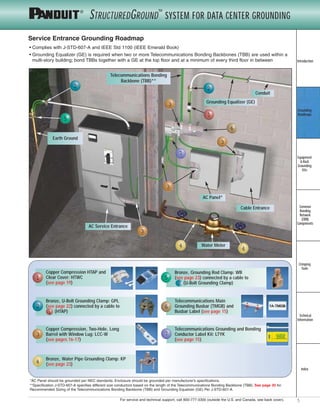
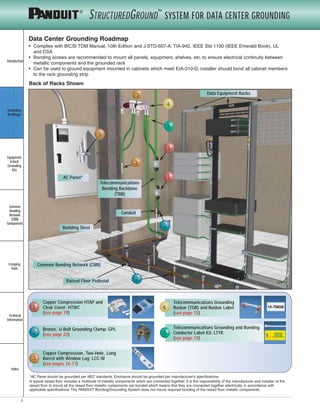
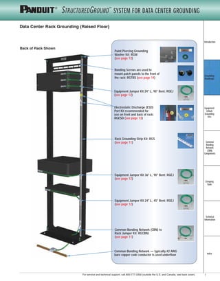
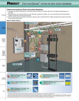
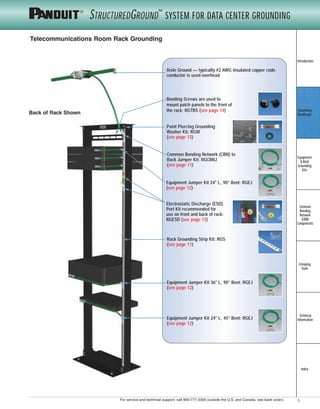
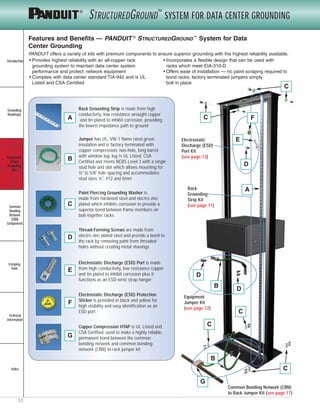
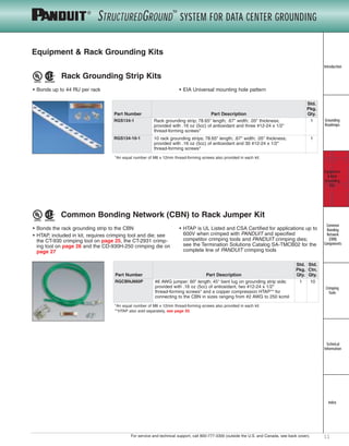
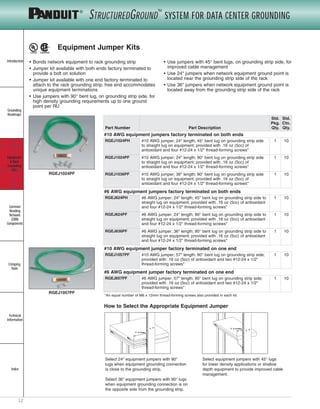
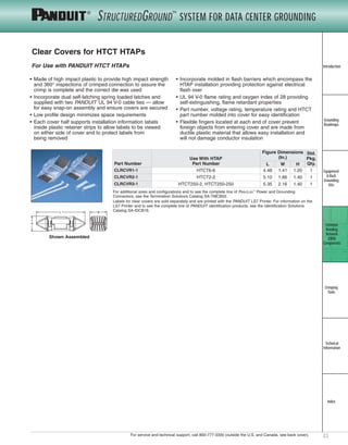
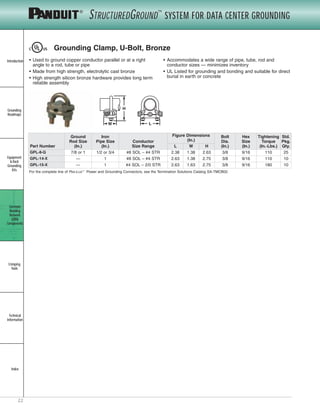
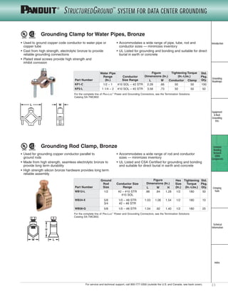
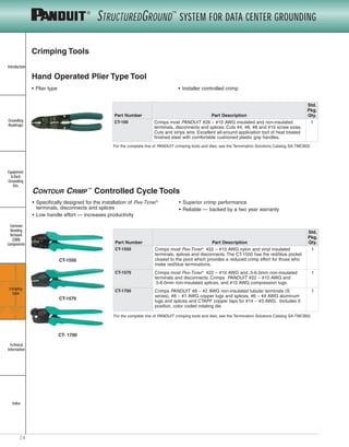
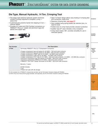
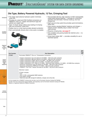
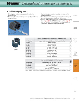
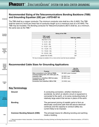
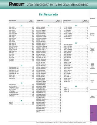
This document is a catalog for the STRUCTUREDGROUNDTM System for Data Center Grounding by PANDUIT. It provides an overview of the system and its components for properly grounding data centers, equipment racks, and telecommunications rooms. The catalog includes grounding roadmaps, technical specifications for products, and references industry standards for data center grounding.
2. Introduction
Grounding
Roadmaps
Equipment
& Rack
Grounding
Kits
Common
Bonding
Network
(CBN)
Components
Crimping
Tools
Technical
Information
Index
2
STRUCTUREDGROUND™
SYSTEM FOR DATA CENTER GROUNDING
How to Use This Catalog
Common Bonding Network (CBN)
page 4
Grounding Roadmaps
pages 5-9
Detailed Product
Information
pages 11-23
Technical Information — Includes Application Standards and BICSI TDM Manual, 10th Edition
pages 28-30
Detailed Tool
Information
pages 24-27
Introduction
Grounding
Roadmaps
Equipment
& Rack
Grounding
Kits
Common
Bonding
Network
(CBN)
Components
Crimping
Tools
Technical
Information
Index
4
STRUCTUREDGROUND™
SYSTEM FOR DATA CENTER GROUNDING
• PANDUIT®
STRUCTUREDGROUND™
System for Data Center Grounding is a complete, highly reliable line of products to ground
your building and network equipment in compliance with BICSI TDM Manual, 10th Edition and J-STD-607-A, TIA-942,
IEEE Std 1100 (IEEE Emerald Book), UL and CSA
Common Bonding Network (CBN)
Telecommunications
Room
(see roadmap on page 8)
Data Center
(see roadmap on page 6)
Service Entrance
(see roadmap on page 5)
See page 28 for PANDUIT®
STRUCTUREDGROUND™
System for Data Center Grounding Application Standards.
For more data center grounding information, see www.panduit.com/dcgrounding.
Introduction
Grounding
Roadmaps
Equipment
& Rack
Grounding
Kits
Common
Bonding
Network
(CBN)
Components
Crimping
Tools
Technical
Information
Index
6
STRUCTUREDGROUND™
SYSTEM FOR DATA CENTER GROUNDING
Data Center Grounding Roadmap
Back of Racks Shown
Telecommunications Grounding
Busbar (TGB) and Busbar Label
(see page 15)
AC Panel*
2
2
3
3
4
1
1
5
Raised Floor Pedestal
Common Bonding Network (CBN)
Building Steel
Conduit
Telecommunications
Bonding Backbone
(TBB)
Data Equipment Racks3
Copper Compression, Two-Hole, Long
Barrel with Window Lug: LCC-W
(see pages 16-17)
Copper Compression HTAP and
Clear Cover: HTWC
(see page 19)
Bronze, U-Bolt Grounding Clamp: GPL
(see page 22)2
3
1 4
Telecommunications Grounding and Bonding
Conductor Label Kit: LTYK
(see page 15)
5
*AC Panel should be grounded per NEC standards. Enclosure should be grounded per manufacturer’s specifications.
A typical raised floor includes a multitude of metallic components which are connected together. It is the responsibility of the manufacturer and installer of the
raised floor to insure all the raised floor metallic components are bonded which means that they are connected together electrically in accordance with
applicable specifications. The PANDUIT Bonding/Grounding System does not insure required bonding of the raised floor metallic components.
• Complies with BICSI TDM Manual, 10th Edition and J-STD-607-A, TIA-942, IEEE Std 1100 (IEEE Emerald Book), UL
and CSA
• Bonding screws are recommended to mount all panels, equipment, shelves, etc. to ensure electrical continuity between
metallic components and the grounded rack
• Can be used to ground equipment mounted in cabinets which meet EIA-310-D; installer should bond all cabinet members
to the rack grounding strip
7For technical assistance in the U.S., call 866-405-6654 (outside the U.S., see inside back cover for directory)
STRUCTUREDGROUND™
System for Data Center Grounding
Introduction
STRUCTUREDGROUND™
System for Data Center Grounding
Introduction
Grounding
Roadmaps
Equipment
& Rack
Grounding
Kits
Common
Bonding
Network
(CBN)
Components
Crimping
Tools
Technical
Information
Index
STRUCTUREDGROUND™
SYSTEM FOR DATA CENTER GROUNDING
Data Center Rack Grounding (Raised Floor)
Back of Rack Shown
Common Bonding Network (CBN) to
Rack Jumper Kit: RGCBNJ
(see page 11)
Common Bonding Network – typically #2 AWG
bare copper code conductor is used underfloor
Equipment Jumper Kit 24" L, 90° Bent: RGEJ
(see page 12)
Equipment Jumper Kit 36" L, 90° Bent: RGEJ
(see page 12)
Equipment Jumper Kit 24" L, 45° Bent: RGEJ
(see page 12)
Electrostatic Discharge (ESD)
Port Kit recommended for
use on front and back of rack:
RGESD (see page 13)
Rack Grounding Strip Kit: RGS
(see page 11)
Bonding Screws are used to
mount patch panels to the front of
the rack: RGTBS (see page 14)
Paint Piercing Grounding
Washer Kit: RGW
(see page 13)
Introduction
Grounding
Roadmaps
Equipment
& Rack
Grounding
Kits
Common
Bonding
Network
(CBN)
Components
Crimping
Tools
Technical
Information
Index
20
STRUCTUREDGROUND™
SYSTEM FOR DATA CENTER GROUNDING
Code/Flex Conductor HTAP
• Used to tap into continuous conductors as a
splice or pigtailing
• Each HTAP terminates a wide range of
conductor sizes and combinations of code
and flex conductors Class G, H, I and
Locomotive to suit a variety of applications
• Slotted design allows quick and easy
assembly of conductor to HTAP using 3
PANDUIT 94 V-0 cable ties included
• Tap grooves are separated from one another
allowing them to function independently so
HTAP can be used with a single or multiple
taps providing maximum design and
installation flexibility
• Color coded and marked with PANDUIT die
index numbers for proper crimp die selection
• Requires crimping tools and dies, see pages
25, 26 and 27
• UL Listed and CSA Certified for applications
up to 600V when crimped with PANDUIT
and specified competitor crimping tools and
PANDUIT crimping dies
• Tin plated to inhibit corrosion
For additional sizes and configurations and to see the complete line of PAN-LUG™
Power and Grounding Connectors, see the Termination Solutions
Catalog SA-TMCB02.
For Making Parallel and Multiple Tap Connections on Code and Flex Conductors
HTAP
TAP
RUN
Part Number
Copper Conductor Size Range
Figure
Dimensions (In.)
PANDUIT
Crimping
Tool
PANDUIT
Die Color
& Die No.
Wire
Strip
Length
(In.)
Std.
Pkg.
Qty.
Wire
Strand
Type Run Tap 1 Tap 2 Tap 3 L W H
HTCT6-6-1
Code
#6 - #10
AWG
#6 - #14
AWG
— —
.61 .40 .99 CT-930, CT-2931 Orange,
PH6
11/16 1
Flex
#6 - #10
AWG
#6 - #14
AWG
HTCT2-2-1
Code
#2 - #6
AWG
STR/SOL
#2 - #6 AWG
STR/SOL
#8 - #14
AWG
#8 - #14
AWG
.76 .61 1.55 CT-930, CT-2931 Brown,
PH2
13/16 1
Flex
#2 - #8
AWG
#2 - #8 AWG #8 - #14
AWG
#8 - #14
AWG
HTCT250-2-1
Code
250 kcmil -
#2 AWG
#2 - #6 AWG
STR/SOL
#8 - #14
AWG
—
.92 .96 1.92 CT-930, CT-2931 Purple,
PH25
1 1
Flex
4/0 - #2
AWG
#2 - #8 AWG #8 - #14
AWG
HTCT250-250-1
Code
250 kcmil -
#2 AWG
250 kcmil -
#2 AWG
— —
.90 .89 1.92 CT-930, CT-2931 Purple,
PH25
1 1
Flex
4/0 - #2
AWG
4/0 - #2
AWG
TAP 1
RUN
H
W
L
W
RUN
TAP 1
TAP 2
TAP 3
L
H
W L
RUN
H
TAP 1 TAP 2 TAP 1
W L
H
RUN
HTCT6-6 HTCT2-2 HTCT250-2 HTCT250-250
Introduction
Grounding
Roadmaps
Equipment
& Rack
Grounding
Kits
Common
Bonding
Network
(CBN)
Components
Crimping
Tools
Technical
Information
Index
26
STRUCTUREDGROUND™
SYSTEM FOR DATA CENTER GROUNDING
Die Type, Battery Powered Hydraulic, 12 Ton, Crimping Tool
• Two stage rapid advance hydraulic system minimizes
cycle time
• Provides UL Listed and CSA Certified connections on
PANDUIT ®
PAN-LUG ™
copper and aluminum lugs and
splices and copper taps
• Open "C-Head" design allows easy loading of crimping
dies and connectors, saves time
• Rubber boot on crimp head provides abrasion protection
• Ram automatically retracts when crimp cycle is complete
• Tool provided with two, high capacity 12 VDC rechargeable
nickel-metal hydride batteries — provides for continuous
operation and eliminates "memory" build-up, one hour
charge time
• Eight second crimp cycle time provides quick terminations,
saves time
• Uses industry standard Makita* batteries and charger —
industry proven reliability easy to obtain from local
retail sources
• Requires crimping dies, see page 27
• Dies installed using spring loaded die retention pins — no
need for tools
• Crimp head rotates 360 degrees — provides versatility for
use in restricted spaces
For the complete line of PANDUIT crimping tools and dies, see the Termination Solutions Catalog SA-TMCB02.
CG-920 crimp force measurement gauge available, sold separately, see the Termination Solutions Catalog SA-TMCB02.
*Makita is a registered trademark of Makita Corporation in the United States.
Part Number Part Description
Std.
Pkg.
Qty.
CT-2931 Terminates PANDUIT ®
PAN-LUG ™
Compression Connectors:
• Copper compression lugs and splices for #8 AWG – 750 kcmil code conductor
• Copper compression lugs and splices for #8 AWG – 600 kcmil flex conductor
• Copper compression CTAPF taps for #10 AWG – 3/0 AWG code conductor
• Copper compression CTAP taps for #8 AWG – 4/0 AWG code conductor
• Copper compression HTCT taps for #14 AWG – 250 kcmil code conductor, #14 AWG – 4/0 AWG flex conductor
• Aluminum compression lugs and splices for #6 AWG – 600 kcmil code conductor
• Aluminum compression HTAPS for #14 AWG – 500 kcmil code conductor
• PANDUIT ®
PAN-TERM ®
Tubular Terminals for #8 AWG – 250 kcmil code conductor
Warranty: 3 years
CT-2931 includes:
• Tool
• Two 12 VDC, rechargeable NiMH batteries
• One battery charger
• Steel tool case with storage for batteries, charger and crimp dies
1
3. 3For service and technical support, call 800-777-3300 (outside the U.S. and Canada, see back cover).
STRUCTUREDGROUND™
System for Data Center Grounding
Introduction
STRUCTUREDGROUND™
System for Data Center Grounding
Introduction
Grounding
Roadmaps
Equipment
& Rack
Grounding
Kits
Common
Bonding
Network
(CBN)
Components
Crimping
Tools
Technical
Information
Index
STRUCTUREDGROUND™
SYSTEM FOR DATA CENTER GROUNDING
What are the effects of improper grounding?
Decreased Efficiency
• Electrical noise is introduced on data cables when surges are not properly dissipated by the grounding system.They cause
faulty data signals and dropped packets,thus decreasing the throughput and overall efficiency of your network.
Lower Reliability
• According to insurance industry data,improper grounding of communication systems leads to $500 million per year of
damage to property and/or equipment due to lightning.(1)
• The InformationTechnology Industry Council states that grounding is the single-most important factor in reliable network
equipment performance.(2)
• More than 90% of problems in data communications equipment,including reboot,lockup,and data corruption,are
traced to problems with grounding.(3)
• Industry experts estimate that 27%-33% of damaged equipment in a user's facility is caused by electrostatic discharge.
The component cost of repairing damaged equipment is substantial for complex circuit boards,especially when labor
and downtime are considered.(4)
• According to the IEEE,the typical AC third prong ground is almost never sufficient to prevent damage to network equipment.(5)
Safety Risks
• Personal injury from electric shock caused by improper grounding can cause immeasurable human suffering and
significant expense.
• Potential fire hazards exist when heat is generated from electrical surges that find a high resistance path to ground.
Can you afford improper grounding?
Network equipment,such as switches,routers and storage devices,costs anywhere from thousands of dollars to hundreds of
thousands of dollars.The cost of proper grounding is only a tiny fraction of the cost of the equipment it is protecting.
Clearly the biggest cost of improper grounding is the inability to service customers properly.
PANDUIT®
STRUCTUREDGROUND™
System for Data Center Grounding gives you what you need to properly protect
your investment.
TThhee PPuurrppoossee ooff GGrroouunnddiinngg
The grounding system is not just an insurance policy against a lightning strike. It is an active,
functioning system that provides protection for personnel and equipment.Proper grounding is
essential for efficient network performance.
The purpose of the grounding system is to create a low impedance path to earth ground for electrical
surges and transient voltages.Lightning,fault currents,circuit switching (motors turning on and off),
and electrostatic discharge are the common causes of these surges and transient voltages. An
effective grounding system minimizes the detrimental effects of these electrical surges.
A properly designed grounding system is one that is intentional,visually verifiable,adequately sized
to handle expected currents safely,and one that directs these potentially damaging currents away
from sensitive communication equipment.Any metallic component that is part of the data center
infrastructure (such as equipment,racks,ladder racks,enclosures,cable trays,etc.) must be bonded
to the grounding system.
1. Mike Holt, "Prevent Shocks in Your Communications: Understanding How the NEC Relies on Ground Resistance Theory Leads to a
Successful Application of Communications Grounding," Electrical Construction & Maintenance, September 2002.
2. Information Technology Industry Council (ITI, formerly CBEMA), Guidelines for Grounding Information Technology Equipment. Information
Letter, ITI, 15 February 1997.
3. Donald G. Pennington and Paul Holzer, "Doing Battle with Those Ground Transients," Electronic Engineering Times, 8 January 1996.
4. ESDA, "Fundamentals of ESD: Part 1 — An Introduction to ESD," 2001, <http://www.esda.org/basics/part1.cfm> (1 October 2004).
5. Institute of Electrical and Electronics Engineers, Inc., IEEE Recommended Practice for Powering and Grounding Electronic Equipment, IEEE
Std 1100-1999, 1999.
4. Introduction
Grounding
Roadmaps
Equipment
& Rack
Grounding
Kits
Common
Bonding
Network
(CBN)
Components
Crimping
Tools
Technical
Information
Index
4
STRUCTUREDGROUND™
SYSTEM FOR DATA CENTER GROUNDING
• PANDUIT ®
STRUCTUREDGROUND™
System for Data Center Grounding is a complete, highly reliable line of products to ground
your building and network equipment in compliance with BICSI TDM Manual, 10th Edition and J-STD-607-A, TIA-942,
IEEE Std 1100 (IEEE Emerald Book), UL and CSA
Common Bonding Network (CBN)
Telecommunications
Room
(see roadmap on page 8)
Data Center
(see roadmap on page 6)
Service Entrance
(see roadmap on page 5)
See page 28 for PANDUIT ®
STRUCTUREDGROUND™
System for Data Center Grounding Application Standards.
For more data center grounding information, see www.panduit.com/dcgrounding.
5. 5For service and technical support, call 800-777-3300 (outside the U.S. and Canada, see back cover).
STRUCTUREDGROUND™
System for Data Center Grounding
Introduction
STRUCTUREDGROUND™
System for Data Center Grounding
Introduction
Grounding
Roadmaps
Equipment
& Rack
Grounding
Kits
Common
Bonding
Network
(CBN)
Components
Crimping
Tools
Technical
Information
Index
STRUCTUREDGROUND™
SYSTEM FOR DATA CENTER GROUNDING
Copper Compression, Two-Hole, Long
Barrel with Window Lug: LCC-W
(see pages 16-17)
Copper Compression HTAP and
Clear Cover: HTWC
(see page 19)
Service Entrance Grounding Roadmap
Bronze, U-Bolt Grounding Clamp: GPL
(see page 22) connected by a cable to
(HTAP)
2
Bronze, Water Pipe Grounding Clamp: KP
(see page 23)
3
4
1
1
2
AC Service Entrance
Earth Ground
3
3
3
2
1
6
3
Telecommunications Bonding
Backbone (TBB)**
Grounding Equalizer (GE)
Cable Entrance
AC Panel*
Water Meter4 4
• Complies with J-STD-607-A and IEEE Std 1100 (IEEE Emerald Book)
• Grounding Equalizer (GE) is required when two or more Telecommunications Bonding Backbones (TBB) are used within a
multi-story building; bond TBBs together with a GE at the top floor and at a minimum of every third floor in between
Telecommunications Grounding and Bonding
Conductor Label Kit: LTYK
(see page 15)
5
5
Telecommunications Main
Grounding Busbar (TMGB) and
Busbar Label (see page 15)
7
7
Bronze, Grounding Rod Clamp: WB
(see page 23) connected by a cable to
(U-Bolt Grounding Clamp)
6
Conduit
*AC Panel should be grounded per NEC standards. Enclosure should be grounded per manufacturer’s specifications.
**Specification J-STD-607-A specifies different size conductors based on the length of the Telecommunications Bonding Backbone (TBB). See page 30 for
Recommended Sizing of the Telecommunications Bonding Backbone (TBB) and Grounding Equalizer (GE) Per J-STD-607-A.
2
6. Introduction
Grounding
Roadmaps
Equipment
& Rack
Grounding
Kits
Common
Bonding
Network
(CBN)
Components
Crimping
Tools
Technical
Information
Index
6
STRUCTUREDGROUND™
SYSTEM FOR DATA CENTER GROUNDING
Data Center Grounding Roadmap
Back of Racks Shown
Telecommunications Grounding
Busbar (TGB) and Busbar Label
(see page 15)
AC Panel*
2
2
3
3
4
1
1
5
Raised Floor Pedestal
Common Bonding Network (CBN)
Building Steel
Conduit
Telecommunications
Bonding Backbone
(TBB)
Data Equipment Racks3
Copper Compression, Two-Hole, Long
Barrel with Window Lug: LCC-W
(see pages 16-17)
Copper Compression HTAP and
Clear Cover: HTWC
(see page 19)
Bronze, U-Bolt Grounding Clamp: GPL
(see page 22)2
3
1 4
Telecommunications Grounding and Bonding
Conductor Label Kit: LTYK
(see page 15)
5
*AC Panel should be grounded per NEC standards. Enclosure should be grounded per manufacturer’s specifications.
A typical raised floor includes a multitude of metallic components which are connected together. It is the responsibility of the manufacturer and installer of the
raised floor to insure all the raised floor metallic components are bonded which means that they are connected together electrically in accordance with
applicable specifications. The PANDUIT Bonding/Grounding System does not insure required bonding of the raised floor metallic components.
• Complies with BICSI TDM Manual, 10th Edition and J-STD-607-A, TIA-942, IEEE Std 1100 (IEEE Emerald Book), UL
and CSA
• Bonding screws are recommended to mount all panels, equipment, shelves, etc. to ensure electrical continuity between
metallic components and the grounded rack
• Can be used to ground equipment mounted in cabinets which meet EIA-310-D; installer should bond all cabinet members
to the rack grounding strip
7. 7For service and technical support, call 800-777-3300 (outside the U.S. and Canada, see back cover).
STRUCTUREDGROUND™
System for Data Center Grounding
Introduction
STRUCTUREDGROUND™
System for Data Center Grounding
Introduction
Grounding
Roadmaps
Equipment
& Rack
Grounding
Kits
Common
Bonding
Network
(CBN)
Components
Crimping
Tools
Technical
Information
Index
STRUCTUREDGROUND™
SYSTEM FOR DATA CENTER GROUNDING
Data Center Rack Grounding (Raised Floor)
Back of Rack Shown
Common Bonding Network (CBN) to
Rack Jumper Kit: RGCBNJ
(see page 11)
Common Bonding Network — typically #2 AWG
bare copper code conductor is used underfloor
Equipment Jumper Kit 24" L, 90° Bent: RGEJ
(see page 12)
Equipment Jumper Kit 36" L, 90° Bent: RGEJ
(see page 12)
Equipment Jumper Kit 24" L, 45° Bent: RGEJ
(see page 12)
Electrostatic Discharge (ESD)
Port Kit recommended for
use on front and back of rack:
RGESD (see page 13)
Rack Grounding Strip Kit: RGS
(see page 11)
Bonding Screws are used to
mount patch panels to the front of
the rack: RGTBS (see page 14)
Paint Piercing Grounding
Washer Kit: RGW
(see page 13)
8. Introduction
Grounding
Roadmaps
Equipment
& Rack
Grounding
Kits
Common
Bonding
Network
(CBN)
Components
Crimping
Tools
Technical
Information
Index
8
STRUCTUREDGROUND™
SYSTEM FOR DATA CENTER GROUNDING
Telecommunications Room Grounding Roadmap
2
1
1
Building Steel
3
3
5
Grounding Equalizer (GE)
Conduit
AC Panel*
Back of Racks Shown
Telecommunications Grounding
Busbar (TGB) and Busbar Label
(see page 15)
Copper Compression, Two-Hole, Long
Barrel with Window Lug: LCC-W
(see pages 16-17)
Copper Compression HTAP and
Clear Cover: HTWC
(see page 19)
Bronze, U-Bolt Grounding Clamp: GPL
(see page 22)2
3
1 4
Telecommunications Grounding and Bonding
Conductor Label Kit: LTYK
(see page 15)
5
*AC Panel should be grounded per NEC standards. Enclosure should be grounded per manufacturer’s specifications.
A typical overhead cabling system includes a multitude of metallic components which are connected together. It is the responsibility of the installer to insure all
of the metallic components are bonded, which means that they are connected together electrically in accordance with applicable specifications. The PANDUIT
Bonding/Grounding System does not insure required bonding of the overhead cabling system metallic components.
3
4
Telecommunications
Bonding Backbone
(TBB)
• Complies with BICSI TDM Manual, 10th Edition and J-STD-607-A, TIA-942, IEEE Std 1100 (IEEE Emerald Book), UL
and CSA
• Bonding screws are recommended to mount all panels, equipment, shelves, etc. to ensure electrical continuity between
metallic components and the grounded rack
• Can be used to ground equipment mounted in cabinets which meet EIA-310-D; installer should bond all cabinet members
to the rack grounding strip
1
9. 9For service and technical support, call 800-777-3300 (outside the U.S. and Canada, see back cover).
STRUCTUREDGROUND™
System for Data Center Grounding
Introduction
STRUCTUREDGROUND™
System for Data Center Grounding
Introduction
Grounding
Roadmaps
Equipment
& Rack
Grounding
Kits
Common
Bonding
Network
(CBN)
Components
Crimping
Tools
Technical
Information
Index
STRUCTUREDGROUND™
SYSTEM FOR DATA CENTER GROUNDING
Telecommunications Room Rack Grounding
Aisle Ground — typically #2 AWG insulated copper code
conductor is used overhead
Back of Rack Shown
Common Bonding Network (CBN) to
Rack Jumper Kit: RGCBNJ
(see page 11)
Equipment Jumper Kit 24" L, 90° Bent: RGEJ
(see page 12)
Equipment Jumper Kit 36" L, 90° Bent: RGEJ
(see page 12)
Equipment Jumper Kit 24" L, 45° Bent: RGEJ
(see page 12)
Electrostatic Discharge (ESD)
Port Kit recommended for
use on front and back of rack:
RGESD (see page 13)
Rack Grounding Strip Kit: RGS
(see page 11)
Bonding Screws are used to
mount patch panels to the front of
the rack: RGTBS (see page 14)
Paint Piercing Grounding
Washer Kit: RGW
(see page 13)
10. Introduction
Grounding
Roadmaps
Equipment
& Rack
Grounding
Kits
Common
Bonding
Network
(CBN)
Components
Crimping
Tools
Technical
Information
Index
10
STRUCTUREDGROUND™
SYSTEM FOR DATA CENTER GROUNDING
Rack Grounding Strip is made from high
conductivity, low resistance wrought copper
and tin plated to inhibit corrosion, providing
the lowest impedance path to ground
Jumper has UL, VW-1 flame rated green
insulation and is factory terminated with
copper compression, two-hole, long barrel
with window lug; lug is UL Listed, CSA
Certified and meets NEBS Level 3 with a single
stud hole and slot which allows mounting for
½" to 5/8" hole spacing and accommodates
stud sizes ¼", #12 and 6mm
Paint Piercing Grounding Washer is
made from hardened steel and electro zinc
plated which inhibits corrosion to provide a
superior bond between frame members on
bolt-together racks
Thread-Forming Screws are made from
electro zinc plated steel and provide a bond to
the rack by removing paint from threaded
holes without creating metal shavings
Electrostatic Discharge (ESD) Port is made
from high conductivity, low resistance copper
and tin plated to inhibit corrosion plus it
functions as an ESD wrist strap hanger
Electrostatic Discharge (ESD) Protection
Sticker is provided in black and yellow for
high visibility and easy identification as an
ESD port
Copper Compression HTAP is UL Listed and
CSA Certified; used to make a highly reliable,
permanent bond between the common
bonding network and common bonding
network (CBN) to rack jumper kit
Features and Benefits — PANDUIT ®
STRUCTUREDGROUND™
System for Data
Center Grounding
PANDUIT offers a variety of kits with premium components to ensure superior grounding with the highest reliability available.
• Provides highest reliability with an all-copper rack
grounding system to maintain data center system
performance and protect network equipment
• Complies with data center standard TIA-942 and is UL
Listed and CSA Certified
• Incorporates a flexible design that can be used with
racks which meet EIA-310-D
• Offers ease of installation — no paint scraping required to
bond racks; factory terminated jumpers simply
bolt in place
Electrostatic
Discharge (ESD)
Port Kit
(see page 13)
Rack
Grounding
Strip Kit
(see page 11)
Common Bonding Network (CBN)
to Rack Jumper Kit (see page 11)
Equipment
Jumper Kit
(see page 12)
A
B
C
D
E
F
G
C
C
C
A
C
C
D
E
F
B
G
B
D
D
11. 11For service and technical support, call 800-777-3300 (outside the U.S. and Canada, see back cover).
STRUCTUREDGROUND™
System for Data Center Grounding
Introduction
STRUCTUREDGROUND™
System for Data Center Grounding
Introduction
Grounding
Roadmaps
Equipment
& Rack
Grounding
Kits
Common
Bonding
Network
(CBN)
Components
Crimping
Tools
Technical
Information
Index
STRUCTUREDGROUND™
SYSTEM FOR DATA CENTER GROUNDING
Equipment & Rack Grounding Kits
Rack Grounding Strip Kits
• Bonds up to 44 RU per rack • EIA Universal mounting hole pattern
Common Bonding Network (CBN) to Rack Jumper Kit
• Bonds the rack grounding strip to the CBN
• HTAP, included in kit, requires crimping tool and die; see
the CT-930 crimping tool on page 25, the CT-2931 crimp-
ing tool on page 26 and the CD-930H-250 crimping die on
page 27
• HTAP is UL Listed and CSA Certified for applications up to
600V when crimped with PANDUIT and specified
competitor crimping tools and PANDUIT crimping dies;
see the Termination Solutions Catalog SA-TMCB02 for the
complete line of PANDUIT crimping tools
*An equal number of M6 x 12mm thread-forming screws also provided in each kit.
**HTAP also sold separately, see page 20.
*An equal number of M6 x 12mm thread-forming screws also provided in each kit.
Part Number Part Description
Std.
Pkg.
Qty.
RGS134-1 Rack grounding strip; 78.65" length; .67" width; .05" thickness;
provided with .16 oz (5cc) of antioxidant and three #12-24 x 1/2"
thread-forming screws*
1
RGS134-10-1 10 rack grounding strips; 78.65" length; .67" width; .05" thickness;
provided with .16 oz (5cc) of antioxidant and 30 #12-24 x 1/2"
thread-forming screws*
1
Part Number Part Description
Std.
Pkg.
Qty.
Std.
Ctn.
Qty.
RGCBNJ660P #6 AWG jumper; 60" length; 45° bent lug on grounding strip side;
provided with .16 oz (5cc) of antioxidant, two #12-24 x 1/2"
thread-forming screws* and a copper compression HTAP** for
connecting to the CBN in sizes ranging from #2 AWG to 250 kcmil
1 10
12. Introduction
Grounding
Roadmaps
Equipment
& Rack
Grounding
Kits
Common
Bonding
Network
(CBN)
Components
Crimping
Tools
Technical
Information
Index
12
STRUCTUREDGROUND™
SYSTEM FOR DATA CENTER GROUNDING
3" or smaller
Equipment Jumper Kits
• Bonds network equipment to rack grounding strip
• Jumper kit available with both ends factory terminated to
provide a bolt on solution
• Jumper kit available with one end factory terminated to
attach to the rack grounding strip; free end accommodates
unique equipment terminations
• Use jumpers with 90° bent lug, on grounding strip side, for
high density grounding requirements up to one ground
point per RU
• Use jumpers with 45° bent lugs, on grounding strip side, for
improved cable management
• Use 24" jumpers when network equipment ground point is
located near the grounding strip side of the rack
• Use 36" jumpers when network equipment ground point is
located away from the grounding strip side of the rack
RGEJ1024PF
3" or larger
RGEJ1057PF
Select equipment jumpers with 45° lugs
for lower density applications or shallow
depth equipment to provide improved cable
management.
Select 24" equipment jumpers with 90°
lugs when equipment grounding connection
is close to the grounding strip.
Select 36" equipment jumpers with 90° lugs
when equipment grounding connection is on
the opposite side from the grounding strip.
How to Select the Appropriate Equipment Jumper
*An equal number of M6 x 12mm thread-forming screws also provided in each kit.
Part Number Part Description
Std.
Pkg.
Qty.
Std.
Ctn.
Qty.
#10 AWG equipment jumpers factory terminated on both ends
RGEJ1024PH #10 AWG jumper; 24" length; 45° bent lug on grounding strip side
to straight lug on equipment; provided with .16 oz (5cc) of
antioxidant and four #12-24 x 1/2" thread-forming screws*
1 10
RGEJ1024PF #10 AWG jumper; 24" length; 90° bent lug on grounding strip side
to straight lug on equipment; provided with .16 oz (5cc) of
antioxidant and four #12-24 x 1/2" thread-forming screws*
1 10
RGEJ1036PF #10 AWG jumper; 36" length; 90° bent lug on grounding strip side
to straight lug on equipment; provided with .16 oz (5cc) of
antioxidant and four #12-24 x 1/2" thread-forming screws*
1 10
#6 AWG equipment jumpers factory terminated on both ends
RGEJ624PH #6 AWG jumper; 24" length; 45° bent lug on grounding strip side to
straight lug on equipment; provided with .16 oz (5cc) of antioxidant
and four #12-24 x 1/2" thread-forming screws*
1 10
RGEJ624PF #6 AWG jumper; 24" length; 90° bent lug on grounding strip side to
straight lug on equipment; provided with .16 oz (5cc) of antioxidant
and four #12-24 x 1/2" thread-forming screws*
1 10
RGEJ636PF #6 AWG jumper; 36" length; 90° bent lug on grounding strip side to
straight lug on equipment; provided with .16 oz (5cc) of antioxidant
and four #12-24 x 1/2" thread-forming screws*
1 10
#10 AWG equipment jumper factory terminated on one end
RGEJ1057PF #10 AWG jumper; 57" length; 90° bent lug on grounding strip side;
provided with .16 oz (5cc) of antioxidant and two #12-24 x 1/2"
thread-forming screws*
1 10
#6 AWG equipment jumper factory terminated on one end
RGEJ657PF #6 AWG jumper; 57" length; 90° bent lug on grounding strip side;
provided with .16 oz (5cc) of antioxidant and two #12-24 x 1/2"
thread-forming screws*
1 10
13. 13For service and technical support, call 800-777-3300 (outside the U.S. and Canada, see back cover).
STRUCTUREDGROUND™
System for Data Center GroundingSTRUCTUREDGROUND™
System for Data Center Grounding
Introduction
Grounding
Roadmaps
Equipment
& Rack
Grounding
Kits
Common
Bonding
Network
(CBN)
Components
Crimping
Tools
Technical
Information
Index
STRUCTUREDGROUND™
SYSTEM FOR DATA CENTER GROUNDING
Electrostatic Discharge (ESD) Port Kit
• Accommodates standard ESD wrist strap 4mm plug
• Can be mounted to front or back of rack for
convenient access
• Bent 45°, acts as a hook to hold wrist strap
• Barrel permanently marked with the protective earth
(ground) symbol
Paint Piercing Grounding Washer Kits
• Bonds frame members on bolt-together racks
• No paint scraping required
• Green color coding to indicate bonding application
Contact your local electrical distributor for their selection of Electrostatic Discharge (ESD) wrist straps.
*One M6 x 12mm thread-forming screw also provided in each kit.
ESD port must be attached to a grounded member.
Part Number Part Description
Std.
Pkg.
Qty.
RGW-12-1 12 paint piercing bonding washers for 3/8" stud size; .875 O.D.; provided
with .16 oz (5cc) of antioxidant; for use with standard equipment racks:
CMR19X84, CMR19X84S and CMR23X84
1
RGW-32-1 32 paint piercing bonding washers for 3/8" stud size; .875 O.D.; provided
with .16 oz (5cc) of antioxidant; for use with 4 post rack NF4PR84 and
data rack DR84
1
RGW-100-1 100 paint piercing bonding washers for 3/8" stud size; .875 O.D.; provided
with .16 oz (5cc) of antioxidant
1
Part Number Part Description
Std.
Pkg.
Qty.
RGESD-1 ESD port kit; provided with an ESD protection sticker, .16 oz (5cc) of
antioxidant and one #12-24 x 1/2" thread-forming screw*
1
14. Introduction
Grounding
Roadmaps
Equipment
& Rack
Grounding
Kits
Common
Bonding
Network
(CBN)
Components
Crimping
Tools
Technical
Information
Index
14
STRUCTUREDGROUND™
SYSTEM FOR DATA CENTER GROUNDING
Thread-Forming Screws
• Thread-forming, provides a bond to the rack by removing
paint from threaded holes without creating metal shavings
• Easily installed with 5/16" socket head wrench or flat
blade screwdriver
Retrofit Rack Grounding Kits
• Provides a dedicated ground system to maintain system
performance and protect network equipment when RGS
rack grounding strip kit cannot be used (see page 11)
• Optimized for installation on 19" racks that meet EIA-310-D,
with functioning equipment, and are deployed in the field
• Provides a complete system of matched components that
can be easily selected to save cost and labor
remove paint from the rack
RGRKCBNJEJ RGRKCBNJ
Network
Equipment
HTAP
(see
page 20)
Rack
Grounding
Busbar
RGRB19
Lug
(see pages
16-18)
Rack
Grounding
Kit
RGRKCBNJEJ
Rack Grounding Kit
RGRKCBNJ
Grounding
Jumper
RGREJ696
or
RGREJ1096
Grounding
Jumper
RGREJ696
Part Number Part Description
Std.
Pkg.
Qty.
Std.
Ctn.
Qty.
RGRKCBNJEJ Rack grounding kit to ground the rack and one piece of equipment;
includes one RGRB19 busbar, one HTCT250-2-1 HTAP and two
RGREJ696 grounding jumpers
1 10
RGRKCBNJ Rack grounding kit to ground the rack; includes one RGRB19
busbar, one HTCT250-2-1 HTAP and one RGREJ696
grounding jumper
1 10
RGRB19 Rack grounding busbar; can be positioned anywhere on the rack;
19" length; tin plated; 14 holes arranged for flexibility in mounting;
mounting hole sets have 1/2" spacing; provided with two
#12-24 x 1/2" thread-forming screws* for mounting
1 10
RGREJ696 Grounding jumper; #6 AWG; 96" length; one end factory
terminated to lug; provided with .16 oz (5cc) of antioxidant and four
#12-24 x 1/2" thread-forming screws* and other mounting hardware
as appropriate
1 10
RGREJ1096 Grounding jumper; #10 AWG; 96" length; one end factory
terminated to lug; provided with .16 oz (5cc) of antioxidant and four
#12-24 x 1/2" thread-forming screws* and other mounting hardware
as appropriate
1 10
Part Number Part Description
Std.
Pkg.
Qty.
RGTS-C Thread-forming grounding screw, #12-24 x 1/2" 100
RGTSM6-C Thread-forming grounding screw, M6 x 12mm 100
Bonding Screws
• Creates an electrical bond between painted patch panels
and racks
• Serrations on bottom of screw remove paint from patch
panel, thus providing metal-to-metal contact
• Thread-forming, provides a bond to the rack by removing
paint from threaded holes without creating metal shavings
• Easily installed with Phillips screwdriver
Part Number Part Description
Std.
Pkg.
Qty.
RGTBS-C Thread-forming bonding screw, #12-24 x 1/2" 100
RGTBSM6-C Thread-forming bonding screw, M6 x 15mm 100
*An equal number of M6 x 12mm thread-forming screws also provided in each kit.
• Thread-forming screws eliminate the need to manually
15. 15For service and technical support, call 800-777-3300 (outside the U.S. and Canada, see back cover).
STRUCTUREDGROUND™
System for Data Center GroundingSTRUCTUREDGROUND™
System for Data Center Grounding
Introduction
Grounding
Roadmaps
Equipment
& Rack
Grounding
Kits
Common
Bonding
Network
(CBN)
Components
Crimping
Tools
Technical
Information
Index
STRUCTUREDGROUND™
SYSTEM FOR DATA CENTER GROUNDING
BICSI/J-STD-607-A Telecommunications Grounding Busbars
Common Bonding Network (CBN) Components
ULRC US
• Meets BICSI and J-STD-607-A requirements for network
systems grounding applications
• Made of high conductivity copper and tin plated to
inhibit corrosion
• Comes pre-assembled with brackets and insulators
attached for quick installation
• Use PANDUIT self-laminating laser/ink jet labels to identify
busbars to meet TIA/EIA-606-A
TGB
TMGB
C200X100FJJ
For additional label sizes, materials and print technologies and to see the complete line of PANDUIT identification
products, see the Identification Solutions Catalog SA-IDCB16.
*Busbar labels sold separately.
Part Number Bar Size
No. of 5/16"
hole sets,
5/8" spacing
No. of 7/16"
hole sets,
1" spacing
Can Be Clearly
Identified with PANDUIT
Laser/Ink Jet Label*
Std.
Pkg.
Qty.
Telecommunications Grounding Busbars (TGB)
GB2B0304TPI-1 1/4" x 2" x 10" 4 3
C200X100FJJ
1
GB2B0306TPI-1 1/4" x 2" x 12" 6 3 1
GB2B0312TPI-1 1/4" x 2" x 20" 12 3 1
Telecommunications Main Grounding Busbars (TMGB)
GB4B0612TPI-1 1/4" x 4" x 12" 12 6
C200X100FJJ
1
GB4B0624TPI-1 1/4" x 4" x 20" 24 6 1
Telecommunications Grounding and Bonding Conductor Label Kit
For additional label sizes, materials and print technologies and to see the complete line of PANDUIT identification
products, see the Identification Solutions Catalog SA-IDCB16.
• Meets labeling requirements of J-STD-607-A; each
telecommunications grounding and bonding conductor shall
be labeled as close as practicable to its point of termination in
a readable position
• Can be applied as a wrap-around marker (parallel to cable) or
flag marker (45° or 90°) to cable
• Kit includes everything needed to properly label cables; one
flame retardant cable tie and one rigid plastic yellow tag
printed with “IF THIS CONNECTOR OR CABLE IS LOOSE
OR MUST BE REMOVED, PLEASE CALL THE BUILDING
TELECOMMUNICATIONS MANAGER”
Part Number Part Description
Std.
Pkg.
Qty.
LTYK Label kit includes printed tag and one flame retardant cable tie 10
16. Introduction
Grounding
Roadmaps
Equipment
& Rack
Grounding
Kits
Common
Bonding
Network
(CBN)
Components
Crimping
Tools
Technical
Information
Index
16
STRUCTUREDGROUND™
SYSTEM FOR DATA CENTER GROUNDING
For Use with Stranded Copper Conductors
Code Conductor, Two-Hole, Long Barrel with Window Lug
• Meets J-STD-607-A requirements for
network systems grounding applications
• Tested by Telcordia — meets NEBS
Level 3
• Requires crimping tools and dies, see
pages 24, 25, 26 and 27
• UL Listed for use up to 35KV**, temperature
rated 90°C and CSA Certified to 600V when
crimped with PANDUIT and specified
competitor crimping tools and dies
• UL Listed and CSA Certified for wire
range-taking capability when crimped with
PANDUIT ®
UNI-DIE ™
dieless crimping tools
• Color coded barrels marked with PANDUIT
and specified competitor die index numbers
for proper crimp die selection
• Long barrel maximizes number of crimps
and provides premium wire pull-out strength
and electrical performance
• Inspection window to visually assure full
conductor insertion
• Tin plated to inhibit corrosion
• Available with NEMA hole sizes and spacing
Ring Terminal, Vinyl Expanded Insulation
• Expanded wire entry allows for large O.D. wire insulation or
multiple wire crimps within one wire barrel
• Industry standard color coding to indicate wire range
• Brazed seam assures a reliable crimp
• Insulation support
• Requires crimping tools, see page 24
C
L
W
For additional sizes and configurations and to see the complete line of PAN-TERM®
Terminals, see the Termination
Solutions Catalog SA-TMCB02.
‡UL and CSA approved tooling/product combinations. For crimping tools see page 24.
**To order in bulk, replace -C in the part number with -M for a bulk package of 1000 and replace -L with -D for a
bulk package of 500.
Part
Number
Wire
Range
Color
Code
Stock
Thickness
Max.
Ins.
Stud
Size
Figure
Dimensions (In.)
PANDUIT
Crimping
Tool
Std.
Pkg.
Qty.**
Std.
Ctn.
Qty.L W C
PV14-6RX-C
16-14
AWG
Blue
.03 .200 #6 .96 .31 .25
CT-100‡,
CT-1550‡
100 500
PV14-8RX-C .03 .200 #8 .96 .31 .25 100 500
PV14-10RX-C .03 .200 #10 .96 .31 .25 100 500
PV14-14RX-C .03 .200 1/4" 1.16 .46 .37 100 500
PV10-6RX-L
12-10
AWG
Yellow
.04 .250 #6 1.10 .31 .30
CT-100‡,
CT-1550‡
50 500
PV10-8RX-L .04 .250 #8 1.10 .31 .30 50 500
PV10-10RX-L .04 .250 #10 1.10 .31 .30 50 500
PV10-14RX-L .04 .250 1/4" 1.29 .52 .39 50 500
17. 17For service and technical support, call 800-777-3300 (outside the U.S. and Canada, see back cover).
STRUCTUREDGROUND™
System for Data Center GroundingSTRUCTUREDGROUND™
System for Data Center Grounding
Introduction
Grounding
Roadmaps
Equipment
& Rack
Grounding
Kits
Common
Bonding
Network
(CBN)
Components
Crimping
Tools
Technical
Information
Index
STRUCTUREDGROUND™
SYSTEM FOR DATA CENTER GROUNDING
W
HOLE
SPACING
L
T
B
INSPECTION
WINDOW
W
HOLE
SPACING
L
T
BINSPECTION
WINDOW
Figure 1 Figure 2: Slotted Lug
B
INSPECTION
WINDOW
W
HOLE
SPACING
L
T
45˚
HOLE
SPACING
L
T
B
INSPECTION
WINDOW
90˚
W
Figure 3: Slotted Lug
45°Bent
Figure 4: Slotted Lug
90°Bent
Code Conductor, Two-Hole, Long Barrel with Window Lug (continued)
For additional sizes and configurations and to see the complete line of PAN-LUG™
Power and Grounding Connectors, see the Termination Solutions
Catalog SA-TMCB02.
*Not tested to NEBS Level 3 requirements.
**Consult cable manufacturer for voltage stress relief instructions with applications greater than 2000V.
Part Number
Figure
No.
Copper
Conductor
Size
Stud
Hole
Size
(In.)
Stud
Hole
Spacing
(In.)
Figure
Dimensions (In.)
PANDUIT
Crimping
Tool
PANDUIT
Die Color
& Die No.
Burndy
Die
No.
T&B
Die
No.
Wire
Strip
Length
(In.)
Std.
Pkg.
Qty.W B T L
LCC10-14JAW-L* 2
#14 – #10
AWG STR,
#12 – #10
AWG SOL
1/4 .50 – .63 .42 .53 .05 1.93
CT-100,
CT-1570
— — — 9/16 50
LCC10-14JAWH-L* 3 1/4 .50 – .63 .42 .53 .05 1.78 — — — 9/16 50
LCC10-14JAWF-L* 4 1/4 .50 – .63 .42 .53 .05 1.56 — — — 9/16 50
LCC10-14BW-L* 1 1/4 .75 .42 .53 .05 2.06 — — — 9/16 50
LCC8-10ABW-L 2
#8 AWG
#10 .63 – .75 .41 .70 .08 2.14
CT-1700,
CT-930,
CT-2931
Red P21 49 21 3/4 50
LCC8-14ABW-L 2 1/4 .63 – .75 .48 .70 .07 2.23 Red P21 49 21 3/4 50
LCC8-14DW-L 1 1/4 1.00 .48 .70 .07 2.48 Red P21 49 21 3/4 50
LCC8-38DW-L 1 3/8 1.00 .60 .70 .05 2.70 Red P21 49 21 3/4 50
LCC6-10ABW-L 2
#6 AWG
#10 .63 – .75 .46 1.07 .08 2.52
CT-1700,
CT-930,
CT-2931
Blue P24 7 24 1 1/8 50
LCC6-14JAW-L 2 1/4 .50 – .63 .48 1.07 .08 2.49 Blue P24 7 24 1 1/8 50
LCC6-14JAWH-L 3 1/4 .50 – .63 .48 1.07 .08 2.08 Blue P24 7 24 1 1/8 50
LCC6-14JAWF-L 4 1/4 .50 – .63 .48 1.07 .08 1.66 Blue P24 7 24 1 1/8 50
LCC6-14BDW-L 2 1/4 .75 – 1.00 .48 1.07 .08 2.86 Blue P24 7 24 1 1/8 50
LCC6-14EW-L 1 1/4 1.25 .48 1.07 .08 3.11 Blue P24 7 24 1 1/8 50
LCC6-56BW-L 1 5/16 .75 .56 1.07 .07 2.73 Blue P24 7 24 1 1/8 50
LCC6-38BDW-L 2 3/8 .75 – 1.00 .62 1.07 .06 3.08 Blue P24 7 24 1 1/8 50
LCC4-14ADW-L 2
#4 – #3
AWG STR
1/4 .63 – 1.00 .55 1.05 .09 2.63 CT-1700,
CT-930,
CT-2931
Gray P29 8 29 1 1/8 50
LCC4-38DW-L 1 3/8 1.00 .62 1.05 .08 3.09 Gray P29 8 29 1 1/8 50
LCC2-14AW-Q 1
#2 AWG
1/4 .63 .60 1.16 .10 2.67 CT-1700,
CT-930,
CT-2931
Brown P33 10 33 1 1/4 25
LCC2-38DW-Q 1 3/8 1.00 .66 1.16 .10 3.24 Brown P33 10 33 1 1/4 25
LCC1-14AW-E 1
#1 AWG
1/4 .63 .70 1.36 .11 2.89 CT-1700,
CT-930,
CT-2931
Green P37 11 37 1 7/16 20
LCC1-38DW-E 1 3/8 1.00 .70 1.36 .11 3.46 Green P37 11 37 1 7/16 20
LCC1/0-14AW-X 1
1/0 AWG
1/4 .63 .76 1.44 .12 3.07 CT-930,
CT-2931
Pink P42 12 42 1 1/2 10
LCC1/0-38DW-X 1 3/8 1.00 .76 1.44 .12 3.57 Pink P42 12 42 1 1/2 10
LCC2/0-14AW-X 1
2/0 AWG
1/4 .63 .85 1.50 .13 3.23 CT-930,
CT-2931
Black P45 13 45 1 9/16 10
LCC2/0-38DW-X 1 3/8 1.00 .85 1.50 .13 3.67 Black P45 13 45 1 9/16 10
LCC3/0-38DW-X 1
3/0 AWG
3/8 1.00 .96 1.50 .13 3.70
CT-930,
CT-2931
Orange P50 14 50 1 9/16 10
LCC3/0-12W-X 1 1/2 1.75 .96 1.50 .13 4.87 Orange P50 14 50 1 9/16 10
LCC4/0-14AW-X 1
4/0 AWG
1/4 .63 1.06 1.56 .14 3.35 CT-930,
CT-2931
Purple P54 15 54 1 5/8 10
LCC4/0-38DW-X 1 3/8 1.00 1.06 1.56 .14 3.81 Purple P54 15 54 1 5/8 10
LCC250-38DW-X 1
250 kcmil
3/8 1.00 1.17 1.61 .14 3.89 CT-930,
CT-2931
Yellow P62 16 62 1 11/16 10
LCC250-12DW-X 1 1/2 1.00 1.17 1.61 .14 4.12 Yellow P62 16 62 1 11/16 10
18. Introduction
Grounding
Roadmaps
Equipment
& Rack
Grounding
Kits
Common
Bonding
Network
(CBN)
Components
Crimping
Tools
Technical
Information
Index
18
STRUCTUREDGROUND™
SYSTEM FOR DATA CENTER GROUNDING
Flex Conductor, Two-Hole, Long Barrel with Window Lug
• Meets J-STD-607-A requirements for
network systems grounding applications
• Requires crimping tools and dies, see pages
24, 25, 26 and 27
• UL Listed for use up to 35KV**, temperature
rated 90°C and CSA Certified to 600V when
crimped with PANDUIT and specified
competitor crimping tools and dies
• Color coded barrels marked with PANDUIT
and specified competitor die index numbers
for proper crimp die selection
• Can be used with code conductor and
flex conductor class: G, H, I, K, M and
Locomotive
• Long barrel maximizes number of crimps
and provides premium wire pull-out strength
and electrical performance
• Inspection window to visually assure full
conductor insertion
• Generously beveled wire entry prevents
bent back strands when inserting conductor
into barrel
• Tin plated to inhibit corrosion
• Available with NEMA hole sizes and spacing
For additional sizes and configurations and to see the complete line of PAN-LUG™
Power and Grounding Connectors, see the Termination Solutions
Catalog SA-TMCB02.
**Consult cable manufacturer for voltage stress relief instructions with applications greater than 2000V.
W
HOLE
SPACING
L
INSPECTION
WINDOW
T
B
For Use with Flexible, Extra-Flexible and Code Stranded Copper Conductors
Figure 1 Figure 2: Slotted Lug
W
HOLE
SPACING
L
T
BINSPECTION
WINDOW
Part Number
Figure
No.
Flex
Conductor
Size Code
Conductor
Size
Stud
Hole
Size
(In.)
Stud
Hole
Spacing
(In.)
Figure
Dimensions
(In.) PANDUIT
Crimping
Tool
PANDUIT
Die Color
& Die No.
Wire
Strip
Length
(In.)
Std.
Pkg.
Qty.
Class
G, H, I, K, M Locomotive W B T L
LCCX8-10AB-L 2
#8 AWG #8 AWG #8 AWG
#10 .63 – .75 .41 .70 .08 2.14
CT-1700,
CT-930,
CT-2931
Red P21 3/4 50
LCCX8-14AB-L 2 1/4 .63 – .75 .48 .70 .07 2.23 Red P21 3/4 50
LCCX8-14D-L 1 1/4 1.00 .48 .70 .07 2.48 Red P21 3/4 50
LCCX8-38D-L 1 3/8 1.00 .60 .70 .05 2.70 Red P21 3/4 50
LCCX6-10B-L 1
#6 AWG #6 AWG #6 AWG
#10 .75 .46 1.07 .08 2.52
CT-1700,
CT-930,
CT-2931
Blue P24 1 1/8 50
LCCX6-14AB-L 2 1/4 .63 – .75 .48 1.07 .08 2.61 Blue P24 1 1/8 50
LCCX6-14D-L 1 1/4 1.00 .48 1.07 .08 2.86 Blue P24 1 1/8 50
LCCX6-38AC-L 2 3/8 .63 – .88 .62 1.07 .06 2.96 Blue P24 1 1/8 50
LCCX6-38D-L 1 3/8 1.00 .62 1.07 .06 3.08 Blue P24 1 1/8 50
LCCX4-14AB-L 2
#4 AWG
#5, #4, #3
AWG
#4 – #3
AWG STR
1/4 .63 – .75 .55 1.05 .09 2.63 CT-1700,
CT-930,
CT-2931
Gray P29 1 1/8 50
LCCX4-38BD-L 2 3/8 .75 – 1.00 .62 1.05 .08 3.09 Gray P29 1 1/8 50
LCCX2-38D-E 1 #2 AWG #2 AWG #2 AWG 3/8 1.00 .70 1.36 .11 3.46 CT-1700,
CT-930,
CT-2931
Brown
P33
1 7/16 20
LCCX1-14A-X 1
#1 AWG #1 AWG #1 AWG
1/4 .63 .76 1.44 .12 3.07 CT-930,
CT-2931
Green P37 1 1/2 10
LCCX1-38D-X 1 3/8 1.00 .76 1.44 .12 3.57 Green P37 1 1/2 10
LCCX1/0-14A-X 1
1/0 AWG 1/0 AWG 1/0 AWG
1/4 .63 .85 1.50 .13 3.23 CT-930,
CT-2931
Pink P42 1 9/16 10
LCCX1/0-38D-X 1 3/8 1.00 .85 1.50 .13 3.67 Pink P42 1 9/16 10
LCCX2/0-14A-X 1
2/0 AWG 2/0 AWG 2/0 AWG
1/4 .63 .96 1.50 .13 3.27 CT-930,
CT-2931
Black P45 1 9/16 10
LCCX2/0-38D-X 1 3/8 1.00 .96 1.50 .13 3.70 Black P45 1 9/16 10
LCCX3/0-38D-X 1 3/0 AWG 3/0 AWG 3/0 AWG 3/8 1.00 1.06 1.56 .14 3.81 CT-930,
CT-2931
Orange
P50
1 5/8 10
LCCX4/0-38D-X 1 4/0 AWG 4/0 AWG 4/0 AWG 3/8 1.00 1.19 2.24 .16 4.55 CT-930,
CT-2931
Purple
P54
2 5/16 10
LCCX250-38D-X 1 250 kcmil 262.6 kcmil — 3/8 1.00 1.28 2.24 .17 4.59 CT-930,
CT-2931
Yellow P62 2 5/16 10
19. 19For service and technical support, call 800-777-3300 (outside the U.S. and Canada, see back cover).
STRUCTUREDGROUND™
System for Data Center Grounding
Introduction
STRUCTUREDGROUND™
System for Data Center Grounding
Introduction
Grounding
Roadmaps
Equipment
& Rack
Grounding
Kits
Common
Bonding
Network
(CBN)
Components
Crimping
Tools
Technical
Information
Index
STRUCTUREDGROUND™
SYSTEM FOR DATA CENTER GROUNDING
Code/Flex Conductor HTAP Kit
• Includes all components to make a complete HTAP and
cover installation: HTCT HTAP, matching CLRCVR clear
cover and cable ties
• Each HTCT HTAP designed to terminate a wide range of
copper code and flex conductor combinations to
accommodate a variety of applications
• HTAPs incorporate a unique slotted design that allows for
quick and easy installation using supplied PANDUIT cable
ties; saves time and cost
• Matching clear covers are made from high impact plastic
and provide high impact strength and 360° viewing of
installed HTAP
• Clear covers have a UL 94 V-0 flame rating and an
oxygen index of 28 providing self-extinguishing, flame
retardant properties
• Requires crimping tools and dies, see pages 25, 26 and
27
• UL Listed and CSA Certified for applications up to 600V
when crimped with PANDUIT and specified competitor
For additional sizes and configurations and to see the complete line of PAN-LUG™
Power and Grounding Connectors, see the Termination Solutions
Catalog SA-TMCB02.
See pages 20 and 21 for more information on HTAPs and clear covers, including crimping tools.
Labels for clear covers are sold separately and are printed with the PANDUIT LS7 Printer. For information on the LS7 Printer and to see the complete line of
PANDUIT identification products, see the Identification Solutions Catalog SA-IDCB16.
TAP 1
RUN
H
W
L
W
RUN
TAP 1
TAP 2
TAP 3
L
H
W L
RUN
H
TAP 1 TAP 2 TAP 1
W L
H
RUN
HTCT6-6 HTCT2-2 HTCT250-2 HTCT250-250
Part Number
Components Copper Conductor Size Range
Std.
Pkg.
Qty.
HTAP
Part No.
Clear
Cover
Part No.
Wire
Strand
Type Run Tap1 Tap 2 Tap 3
HTWC6-6-1 HTCT6-6-1 CLRCVR1-1 Code #6 – #10 AWG #6 – #14 AWG
— —
1
Flex #6 – #10 AWG #6 – #14 AWG
HTWC2-2-1 HTCT2-2-1 CLRCVR2-1
Code
#2 – #6 AWG
STR/SOL
#2 – #6 AWG
STR/SOL
#8 – #14 AWG #8 – #14 AWG 1
Flex #2 – #8 AWG #2 – #8 AWG #8 – #14 AWG #8 – #14 AWG
HTWC250-2-1 HTCT250-2-1 CLRCVR3-1
Code
250 kcmil – #2
AWG
#2 – #6 AWG
STR/SOL
#8 – #14 AWG
—
1
Flex 4/0 – #2 AWG #2 – #8 AWG #8 – #14 AWG
HTWC250-250-1 HTCT250-250-1 CLRCVR3-1
Code
250 kcmil – #2
AWG
250 kcmil – #2
AWG — —
1
Flex 4/0 – #2 AWG 4/0 – #2 AWG
20. Introduction
Grounding
Roadmaps
Equipment
& Rack
Grounding
Kits
Common
Bonding
Network
(CBN)
Components
Crimping
Tools
Technical
Information
Index
20
STRUCTUREDGROUND™
SYSTEM FOR DATA CENTER GROUNDING
Code/Flex Conductor HTAP
• Used to tap into continuous conductors as a
splice or pigtailing
• Each HTAP terminates a wide range of
conductor sizes and combinations of code
and flex conductors Class G, H, I and
Locomotive to suit a variety of applications
• Slotted design allows quick and easy
assembly of conductor to HTAP using 3
PANDUIT 94 V-0 cable ties included
• Tap grooves are separated from one another
allowing them to function independently so
HTAP can be used with a single or multiple
taps providing maximum design and
installation flexibility
• Color coded and marked with PANDUIT die
index numbers for proper crimp die selection
• Requires crimping tools and dies, see
pages 25, 26 and 27
• UL Listed and CSA Certified for applications
up to 600V when crimped with PANDUIT
and specified competitor crimping tools and
PANDUIT crimping dies
• Tin plated to inhibit corrosion
For additional sizes and configurations and to see the complete line of PAN-LUG™
Power and Grounding Connectors, see the Termination Solutions
Catalog SA-TMCB02.
For Making Parallel and Multiple Tap Connections on Code and Flex Conductors
HTAP
TAP
RUN
TAP 1
RUN
H
W
L
W
RUN
TAP 1
TAP 2
TAP 3
L
H
W L
RUN
H
TAP 1 TAP 2 TAP 1
W L
H
RUN
HTCT6-6 HTCT2-2 HTCT250-2 HTCT250-250
Part Number
Copper Conductor Size Range
Figure
Dimensions (In.)
PANDUIT
Crimping
Tool
PANDUIT
Die Color
& Die No.
Wire
Strip
Length
(In.)
Std.
Pkg.
Qty.
Wire
Strand
Type Run Tap 1 Tap 2 Tap 3 L W H
HTCT6-6-1
Code
#6 – #10
AWG
#6 – #14
AWG
— —
.61 .40 .99 CT-930, CT-2931 Orange,
PH6
11/16 1
Flex
#6 – #10
AWG
#6 – #14
AWG
HTCT2-2-1
Code
#2 – #6
AWG
STR/SOL
#2 – #6 AWG
STR/SOL
#8 – #14
AWG
#8 – #14
AWG
.76 .61 1.55 CT-930, CT-2931 Brown,
PH2
13/16 1
Flex
#2 – #8
AWG
#2 – #8 AWG #8 – #14
AWG
#8 – #14
AWG
HTCT250-2-1
Code
250 kcmil –
#2 AWG
#2 – #6 AWG
STR/SOL
#8 – #14
AWG
—
.92 .96 1.92 CT-930, CT-2931 Purple,
PH25
1 1
Flex
4/0 – #2
AWG
#2 – #8 AWG #8 – #14
AWG
HTCT250-250-1
Code
250 kcmil –
#2 AWG
250 kcmil –
#2 AWG
— —
.90 .89 1.92 CT-930, CT-2931 Purple,
PH25
1 1
Flex
4/0 – #2
AWG
4/0 – #2
AWG
21. 21For service and technical support, call 800-777-3300 (outside the U.S. and Canada, see back cover).
STRUCTUREDGROUND™
System for Data Center Grounding
Introduction
STRUCTUREDGROUND™
System for Data Center Grounding
Introduction
Grounding
Roadmaps
Equipment
& Rack
Grounding
Kits
Common
Bonding
Network
(CBN)
Components
Crimping
Tools
Technical
Information
Index
STRUCTUREDGROUND™
SYSTEM FOR DATA CENTER GROUNDING
Clear Covers for HTCT HTAPs
• Made of high impact plastic to provide high impact strength
and 360° inspections of crimped connection to assure the
crimp is complete and the correct die was used
• Incorporate dual self-latching spring loaded latches and
supplied with two PANDUIT UL 94 V-0 cable ties — allow
for easy snap-on assembly and ensure covers are secured
• Low profile design minimizes space requirements
• Each cover half supports installation information labels
inside plastic retainer strips to allow labels to be viewed
on either side of cover and to protect labels from
being removed
• Incorporate molded in flash barriers which encompass the
HTAP installation providing protection against electrical
flash over
• UL 94 V-0 flame rating and oxygen index of 28 providing
self-extinguishing, flame retardant properties
• Part number, voltage rating, temperature rating and HTCT
part number molded into cover for easy identification
• Flexible fingers located at each end of cover prevent
foreign objects from entering cover and are made from
ductile plastic material that allows easy installation and
will not damage conductor insulation
For additional sizes and configurations and to see the complete line of PAN-LUG™
Power and Grounding
Connectors, see the Termination Solutions Catalog SA-TMCB02.
Labels for clear covers are sold separately and are printed with the PANDUIT LS7 Printer. For information on the
LS7 Printer and to see the complete line of PANDUIT identification products, see the Identification Solutions
Catalog SA-IDCB16.
H
L W
Part Number
Use With HTAP
Part Number
Figure Dimensions
(In.)
Std.
Pkg.
Qty.L W H
CLRCVR1-1 HTCT6-6 4.48 1.41 1.20 1
CLRCVR2-1 HTCT2-2 5.10 1.66 1.40 1
CLRCVR3-1 HTCT250-2, HTCT250-250 5.35 2.16 1.40 1
Shown Assembled
For Use with PANDUIT HTCT HTAPs
22. Introduction
Grounding
Roadmaps
Equipment
& Rack
Grounding
Kits
Common
Bonding
Network
(CBN)
Components
Crimping
Tools
Technical
Information
Index
22
STRUCTUREDGROUND™
SYSTEM FOR DATA CENTER GROUNDING
Grounding Clamp, U-Bolt, Bronze
• Used to ground copper conductor parallel or at a right
angle to a rod, tube or pipe
• Made from high strength, electrolytic cast bronze
• High strength silicon bronze hardware provides long term
reliable assembly
• Accommodates a wide range of pipe, tube, rod and
conductor sizes — minimizes inventory
• UL Listed for grounding and bonding and suitable for direct
burial in earth or concrete
For the complete line of PAN-LUG™
Power and Grounding Connectors, see the Termination Solutions Catalog SA-TMCB02.
ULRC US
H
LW
Part Number
Ground
Rod Size
(In.)
Iron
Pipe Size
(In.)
Conductor
Size Range
Figure Dimensions
(In.)
Bolt
Dia.
(In.)
Hex
Size
(In.)
Tightening
Torque
(In.-Lbs.)
Std.
Pkg.
Qty.L W H
GPL-8-Q 7/8 or 1 1/2 or 3/4 #8 SOL – #4 STR 2.38 1.38 2.63 3/8 9/16 110 25
GPL-14-X — 1 #8 SOL – #4 STR 2.63 1.38 2.75 3/8 9/16 110 10
GPL-15-X — 1 #4 SOL – 2/0 STR 2.63 1.63 2.75 3/8 9/16 180 10
23. 23For service and technical support, call 800-777-3300 (outside the U.S. and Canada, see back cover).
STRUCTUREDGROUND™
System for Data Center Grounding
Introduction
STRUCTUREDGROUND™
System for Data Center Grounding
Introduction
Grounding
Roadmaps
Equipment
& Rack
Grounding
Kits
Common
Bonding
Network
(CBN)
Components
Crimping
Tools
Technical
Information
Index
STRUCTUREDGROUND™
SYSTEM FOR DATA CENTER GROUNDING
Grounding Clamp for Water Pipes, Bronze
• Used to ground copper code conductor to water pipe or
copper tube
• Cast from high strength, electrolytic bronze to provide
reliable grounding connections
• Plated steel screws provide high strength and
inhibit corrosion
• Accommodates a wide range of pipe, tube, rod and
conductor sizes — minimizes inventory
• UL Listed for grounding and bonding and suitable for direct
burial in earth or concrete
For the complete line of PAN-LUG™
Power and Grounding Connectors, see the Termination Solutions
Catalog SA-TMCB02.
L W
Grounding Rod Clamp, Bronze
• Used for grounding copper conductor parallel to
ground rods
• Made from high strength, seamless electrolytic bronze to
provide long term durability
• High strength silicon bronze hardware provides long term
reliable assembly
• Accommodates a wide range of rod and conductor
sizes — minimizes inventory
• UL Listed and CSA Certified for grounding and bonding
and suitable for direct burial in earth and concrete
For the complete line of PAN-LUG™
Power and Grounding Connectors, see the Termination Solutions
Catalog SA-TMCB02.
Part Number
Ground
Rod
Size
Conductor Size
Range
Figure
Dimensions (In.)
Hex
Size
(In.)
Tightening
Torque
(In.-Lbs.)
Std.
Pkg.
Qty.L W H
WB12-L 1/2 #2 – #10 STR
#10 SOL
.88 .84 1.28 1/2 180 50
WB34-X 5/8
3/4
1/0 – #8 STR
#2 – #8 STR
1.03 1.06 1.54 1/2 180 10
WB58-Q 5/8 1/0 – #8 STR 1.04 .92 1.40 1/2 180 25
W L
H
Part Number
Water Pipe
Range
(In.)
Conductor
Size Range
Figure
Dimensions (In.)
Tightening Torque
(In.-Lbs.)
Std.
Pkg.
Qty.L W Conductor Clamp
KP1-C 1/2 – 1 #10 SOL – #2 STR 2.28 .66 50 50 100
KP2-L 1 1/4 – 2 #10 SOL – #2 STR 3.58 .73 50 50 50
24. Introduction
Grounding
Roadmaps
Equipment
& Rack
Grounding
Kits
Common
Bonding
Network
(CBN)
Components
Crimping
Tools
Technical
Information
Index
24
STRUCTUREDGROUND™
SYSTEM FOR DATA CENTER GROUNDING
Hand Operated Plier Type Tool
Crimping Tools
• Plier type • Installer controlled crimp
For the complete line of PANDUIT crimping tools and dies, see the Termination Solutions Catalog SA-TMCB02.
Part Number Part Description
Std.
Pkg.
Qty.
CT-100 Crimps most PANDUIT #26 – #10 AWG insulated and non-insulated
terminals, disconnects and splices. Cuts #4, #6, #8 and #10 screw sizes.
Cuts and strips wire. Excellent all-around application tool of heat treated
finished steel with comfortable cushioned plastic grip handles.
1
CONTOUR CRIMP™
Controlled Cycle Tools
• Specifically designed for the installation of PAN-TERM ®
terminals, disconnects and splices
• Low handle effort — increases productivity
• Superior crimp performance
• Reliable — backed by a two year warranty
CT-1550
CT- 1700
For the complete line of PANDUIT crimping tools and dies, see the Termination Solutions Catalog SA-TMCB02.
Part Number Part Description
Std.
Pkg.
Qty.
CT-1550 Crimps most PAN-TERM®
#22 – #10 AWG nylon and vinyl insulated
terminals, splices and disconnects. The CT-1550 has the red/blue pocket
closest to the pivot which provides a reduced crimp effort for those who
make red/blue terminations.
1
CT-1570 Crimps most PAN-TERM®
#22 – #10 AWG and .5-6.0mm non-insulated
terminals and disconnects. Crimps PANDUIT #22 – #10 AWG and
.5-6.0mm non-insulated splices, and #10 AWG compression lugs.
1
CT-1700 Crimps PANDUIT #8 – #2 AWG non-insulated tubular terminals (S
series), #8 – #1 AWG copper lugs and splices, #6 – #4 AWG aluminum
lugs and splices and CTAPF copper taps for #14 – #3 AWG. Includes 5
position, color coded rotating die.
1
CT-1570
25. 25For service and technical support, call 800-777-3300 (outside the U.S. and Canada, see back cover).
STRUCTUREDGROUND™
System for Data Center Grounding
Introduction
STRUCTUREDGROUND™
System for Data Center Grounding
Introduction
Grounding
Roadmaps
Equipment
& Rack
Grounding
Kits
Common
Bonding
Network
(CBN)
Components
Crimping
Tools
Technical
Information
Index
STRUCTUREDGROUND™
SYSTEM FOR DATA CENTER GROUNDING
Die Type, Manual Hydraulic, 14 Ton, Crimping Tool
• Two-stage rapid advance hydraulic system minimizes
number of pumps required to complete a crimp —
saves time
• Cushioned grip prevents hands from slipping on tool —
reduces fatigue
• Provides UL Listed and CSA Certified connections on
PANDUIT ®
PAN-LUG™
copper and aluminum lugs and
splices and copper taps
• Open “C-Head” design allows easy loading of crimping dies
and connectors, saves time
• Requires crimping dies, see page 27
• Dies installed using spring loaded die retention pins, no
need for tools
• Rubber boot on crimp head provides abrasion protection
• Audible “pop-off” valve indicates crimp completion
• Crimp head rotates 180°, provides versatility for use in
restricted spaces
For the complete line of PANDUIT crimping tools and dies, see the Termination Solutions Catalog SA-TMCB02.
CG-920 crimp force measurement gauge available, sold separately, see the Termination Solutions Catalog SA-TMCB02.
Part Number Part Description
Std.
Pkg.
Qty.
CT-930 Terminates PANDUIT ®
PAN-LUG™
Compression Connectors:
• Copper compression lugs and splices for #8 AWG – 750 kcmil code conductor
• Copper compression lugs and splices for #8 AWG – 600 kcmil flex conductor
• Copper compression CTAPF taps for #10 AWG – 3/0 AWG code conductor
• Copper compression CTAP taps for #8 AWG – 4/0 AWG code conductor
• Copper compression HTCT taps for #14 AWG – 250 kcmil code conductor, #14 AWG – 4/0 AWG flex conductor
• Aluminum compression lugs and splices for #6 AWG – 600 kcmil code conductor
• Aluminum compression HTAPS for #14 AWG – 500 kcmil code conductor
• PANDUIT ®
PAN-TERM®
Tubular Terminals for #8 AWG – 250 kcmil code conductor
Warranty: 5 years
CT-930 includes:
• Tool
• Plastic tool case with die storage
1
26. Introduction
Grounding
Roadmaps
Equipment
& Rack
Grounding
Kits
Common
Bonding
Network
(CBN)
Components
Crimping
Tools
Technical
Information
Index
26
STRUCTUREDGROUND™
SYSTEM FOR DATA CENTER GROUNDING
Die Type, Battery Powered Hydraulic, 12 Ton, Crimping Tool
• Two stage rapid advance hydraulic system minimizes
cycle time
• Provides UL Listed and CSA Certified connections on
PANDUIT ®
PAN-LUG™
copper and aluminum lugs and
splices and copper taps
• Open “C-Head” design allows easy loading of crimping
dies and connectors, saves time
• Rubber boot on crimp head provides abrasion protection
• Ram automatically retracts when crimp cycle is complete
• Tool provided with two, high capacity 12 VDC rechargeable
nickel-metal hydride batteries — provides for continuous
operation and eliminates “memory” build-up, one hour
charge time
• Eight second crimp cycle time provides quick terminations,
saves time
• Uses industry standard Makita* batteries and charger —
industry proven reliability easy to obtain from local
retail sources
• Requires crimping dies, see page 27
• Dies installed using spring loaded die retention pins — no
need for tools
• Crimp head rotates 360° — provides versatility for use in
restricted spaces
For the complete line of PANDUIT crimping tools and dies, see the Termination Solutions Catalog SA-TMCB02.
CG-920 crimp force measurement gauge available, sold separately, see the Termination Solutions Catalog SA-TMCB02.
*Makita is a registered trademark of Makita Corporation.
Part Number Part Description
Std.
Pkg.
Qty.
CT-2931 Terminates PANDUIT ®
PAN-LUG™
Compression Connectors:
• Copper compression lugs and splices for #8 AWG – 750 kcmil code conductor
• Copper compression lugs and splices for #8 AWG – 600 kcmil flex conductor
• Copper compression CTAPF taps for #10 AWG – 3/0 AWG code conductor
• Copper compression CTAP taps for #8 AWG – 4/0 AWG code conductor
• Copper compression HTCT taps for #14 AWG – 250 kcmil code conductor, #14 AWG – 4/0 AWG flex conductor
• Aluminum compression lugs and splices for #6 AWG – 600 kcmil code conductor
• Aluminum compression HTAPS for #14 AWG – 500 kcmil code conductor
• PANDUIT ®
PAN-TERM ®
Tubular Terminals for #8 AWG – 250 kcmil code conductor
Warranty: 3 years
CT-2931 includes:
• Tool
• Two 12 VDC, rechargeable NiMH batteries
• One battery charger
• Steel tool case with storage for batteries, charger and crimp dies
1
27. 27For service and technical support, call 800-777-3300 (outside the U.S. and Canada, see back cover).
STRUCTUREDGROUND™
System for Data Center Grounding
Introduction
STRUCTUREDGROUND™
System for Data Center Grounding
Introduction
Grounding
Roadmaps
Equipment
& Rack
Grounding
Kits
Common
Bonding
Network
(CBN)
Components
Crimping
Tools
Technical
Information
Index
STRUCTUREDGROUND™
SYSTEM FOR DATA CENTER GROUNDING
CD-920 Crimping Dies
• Crimping dies and connectors are color coded for
easy matching
• Embosses die index number on connector barrels for post
crimp inspection
• Part number permanently marked on crimping die for
easy identification
• Provides circumferential crimp results in terminations with
premium electrical and mechanical performance
• Used in PANDUIT crimping tools; see the CT-930 crimping
tool on page 25, the CT-2931 crimping tool on page 26
and the complete line of PANDUIT crimping tools in the
Termination Solutions Catalog SA-TMCB02
CD-920
For the complete line of PANDUIT crimping tools and dies, see the Termination Solutions Catalog SA-TMCB02.
Die Number
Die
Color
Part Number
Used to Install PANDUIT HTAP Part Numbers Std.
Pkg.
Qty.Copper HTAP and Die Color & Die No.
CD-920H-6 HTCT6-6-1, Orange PH6 1
CD-920H-2 HTCT2-2-1, Brown PH2 1
CD-930H-250 HTCT250-2-1,
HTCT250-250-1, Purple PH25
1
Part Number
Used to Install PANDUIT Compression Lug & Splice Sizes Std.
Pkg.
Qty.Copper Code Conductor Size and Die Color & Die No.
CD-920-8 #8 AWG, Red P21 1
CD-920-6 #6 AWG, Blue P24 1
CD-920-4 #4 AWG, Gray P29 1
CD-920-2 #2 AWG, Brown P33 1
CD-920-1 #1 AWG, Green P37 1
CD-920-1/0 1/0 AWG, Pink P42 1
CD-920-2/0 2/0 AWG, Black P45 1
CD-920-3/0 3/0 AWG, Orange P50 1
CD-920-4/0 4/0 AWG, Purple P54 1
CD-920-250 250 kcmil, Yellow P62 1
28. Introduction
Grounding
Roadmaps
Equipment
& Rack
Grounding
Kits
Common
Bonding
Network
(CBN)
Components
Crimping
Tools
Technical
Information
Index
28
STRUCTUREDGROUND™
SYSTEM FOR DATA CENTER GROUNDING
PANDUIT ®
STRUCTUREDGROUND™
System for Data Center Grounding
Application Standards
IEEE Std 1100-1999 (IEEE Emerald Book) – IEEE
Recommended Practice for Powering and Grounding
Electronic Equipment
The main objective of the Emerald Book is to provide a consensus of
recommended practices to address electronic equipment
performance issues while maintaining a safe installation, as
specified in the National Electrical Code®
(NEC®
) (NFPA 70-1999)
and recognized testing laboratories' standards.
Alliance for Telecommunications Industry
Solutions ATIS
ATIS is a technical planning and standards development
organization that is committed to rapidly developing and promoting
technical and operations standards for the communications and
related information technologies industry worldwide using a
pragmatic, flexible and open approach. Over 1,200 participants from
more than 400 communications companies are active in ATIS’ 22
industry committees, and its Incubator Solutions Program.
www.atis.org
J-STD-607-A-2002, Commercial Building Grounding
(Earthing) and Bonding Requirements for
Telecommunications is jointly developed by TIA/EIA and ATIS’
technical committee T1E1. This document is available on the
ATIS Document Center at www.atis.org.
Adhering to the grounding principles outlined in J-STD-607-A helps
ensure that telecommunications equipment and systems
operate reliably. As stated in J-STD-607-A, the preferred means of
connecting conductors to busbars is by using two-hole
irreversible compression lugs listed by a nationally recognized
testing laboratory (NRTL) such as UL. PANDUIT ®
PAN-LUG™
Copper
Compression Connectors meet these requirements, in all of the
barrel sizes specified by the 607 standard.
Telecommunications Industry Association TIA
The Telecommunications Industry Association is a leading U.S.
non-profit trade association serving the communications and
information technology industry. TIA represents providers of
communications and information technology products and services
for the global marketplace through its core competencies in
standards development.
ANSI/TIA-942 Draft 5.0a – Telecommunications
Infrastructure Standard for Data Centers
TIA-942 states that electrical continuity is required throughout the
rack materials. Adhering to these principles protects network
equipment and maintains system performance. PANDUIT ®
STRUCTUREDGROUND™
System for Data Center Grounding meets
TIA-942 requirements by incorporating an all-copper grounding path.
Paint piercing grounding washers ensure metal to metal contact of
rack members and two-hole compression lugs for a permanent and
reliable connection.
The Institute of Electrical and Electronics
Engineers, Inc. (IEEE)
The IEEE promotes the engineering process of creating,
developing, integrating, sharing, and applying knowledge about
electro and information technologies and sciences for the benefit
of humanity and the profession.
NEBS Level 3 Criteria is the minimum level of
environmental compatibility needed to provide maximum
assurance of equipment operability within the network
facility environment.
The Level 3 Criteria is the highest assurance of product operability.
Products that meet NEBS Level 3 Criteria are suited for equipment
applications which demand minimal service interruptions over the life
span of the equipment. PANDUIT is the first in the industry to have a
system of copper compression lugs and splices (#8 AWG – 1,000
kcmil) and crimping tools physically and rigorously tested by
Telcordia Technologies to meet NEBS Level 3 compliance.
NEBS Level 3 Approval as Tested by Telcordia Technologies
Telcordia Technologies, formerly known as Bellcore, serves as the
testing agency for the Regional Bell Operating Companies. Network
Equipment-Building Systems (NEBS) was developed by Bellcore
and is currently maintained by Telcordia Technologies. NEBS was
developed to standardize requirements for Central Office Equipment
and to develop criteria for personal safety, protection of property and
operational continuity.
Canadian Standards Association
Canadian Standards Association is a not-for-profit membership
based association serving business, industry, government, and
consumers in Canada and the global marketplace. C.S.A. works in
Canada and around the world to develop standards that enhance
public safety and health.
Underwriters Laboratories, Inc.
Underwriters Laboratories, Inc. is an independent, not-for-profit
safety testing and certification organization based in the
United States.
• UL 467 Grounding and Bonding Equipment
• UL 486A Wire Connectors and Soldering Lugs for Use with
Copper Conductors – Covers pressure wire connectors and
soldering lugs for use with copper conductors according to the
National Electrical Code NFPA 70
• UL VW-1 Flammability Rating
Underwriters Laboratories, Inc. Standards applicable to specified
PANDUIT ®
STRUCTUREDGROUND™
System for Data Center Grounding
and PAN-LUG™
Power and Grounding Connectors.
• C22.2 NO. 41-M1987 (R2004) Grounding and
Bonding Equipment
• C22.2 NO. 65-03 Wire Connectors
Canadian Standards Association standards that are applicable to
specified PANDUIT ®
STRUCTUREDGROUND™
System for Data Center
Grounding and PAN-LUG™
Power and Grounding Connectors.
29. 29For service and technical support, call 800-777-3300 (outside the U.S. and Canada, see back cover).
STRUCTUREDGROUND™
System for Data Center Grounding
Introduction
STRUCTUREDGROUND™
System for Data Center Grounding
Introduction
Grounding
Roadmaps
Equipment
& Rack
Grounding
Kits
Common
Bonding
Network
(CBN)
Components
Crimping
Tools
Technical
Information
Index
STRUCTUREDGROUND™
SYSTEM FOR DATA CENTER GROUNDING
Roof
Backbone pathway
Suspended ceiling area
TR
Buildingsteel
TGB
GE
TR
TGB
TGB TGB
Buildingsteel
Backbone pathway
Backbone pathway
Suspended ceiling area
TR
(TBB)
Exteriorbuildingwall
TBB
Sleeve
Suspended ceiling area
TBB within conduit
ACEG
(TBB)
Electrical
EF
Grounding
electrode
system
GEC
TMGB
BCT
Primary
cable
protection
EF ER
Panel
board
TGB
(TBB)
TR
ACEG = Alternating current equipment ground
BC = Bonding conductor
BCT = Bonding conductor for telecommunications
EF = Entrance facility
ER = Equipment room
GE = Grounding equalizer
GEC = Grounding electrode conductor
TBB = Telecommunications bonding backbone
TGB = Telecommunications grounding busbar
TMGB = Telecommunications main grounding busbar
TR = Telecommunications room
Red
iron
Red
iron
Red
iron
GE
Source: BICSI TDM Manual, 10th Edition
Specification Layout for Data Center Grounding per BICSI TDM Manual,
10th Edition
For more technical grounding information, please see the Data Center Grounding White Paper at www.panduit.com/dcgrounding.
30. Introduction
Grounding
Roadmaps
Equipment
& Rack
Grounding
Kits
Common
Bonding
Network
(CBN)
Components
Crimping
Tools
Technical
Information
Index
30
STRUCTUREDGROUND™
SYSTEM FOR DATA CENTER GROUNDING
Ground A conducting connection, whether intentional or
accidental, by which an electric circuit or equipment is
connected to the earth, or to some conducting body of
relatively large extent that serves in place of the earth.
Bonding The permanent joining of metallic parts to form an
electrically conductive path that will assure electrical
continuity and the capacity to conduct safely any
current likely to be imposed.
Common Bonding Network (CBN) The principal means for affecting bonding and earthing
inside a building.
Key Terminology
Recommended Sizing of the Telecommunications Bonding Backbone (TBB)
and Grounding Equalizer (GE) per J-STD-607-A
Recommended Cable Sizes for Grounding Applications
The TBB shall be a copper conductor. The minimum conductor size shall be a No. 6 AWG. The TBB
shall be sized at 2 kcmil per linear foot of conductor length up to a maximum size of a 3/0 AWG. The
TBB may be insulated. The Bonding conductor for Telecommunications (BCT) shall be, as a minimum,
the same size as the TBB.(1)
1. Telecommunications Industry Association, Commercial Building Grounding (Earthing) and Bonding Requirements For Telecommunications, J-STD-607-A,
October 2002.
Purpose
Use the
Following
Code Cables
Other connections to the TGB and TMGB,
including building steel, main water pipe, etc.
#6 AWG, green insulated
Underfloor CBN #2 AWG, bare
Connections to Underfloor CBN from pipes,
ventilation ducts, etc.
#6 AWG, bare
Connection from Underfloor CBN to TGB 2/0 AWG, bare
Sizing of the TBB
TBB Length
linear M (ft) TBB Size (AWG)
less than 4 (13) 6
4 – 6 (14 – 20) 4
6 – 8 (21 – 26) 3
8 – 10 (27 – 33) 2
10 – 13 (34 – 41) 1
13 – 16 (42 – 52) 1/0
16 – 20 (53 – 66) 2/0
greater than 20 (66) 3/0*
*3/0 may not always be available. 4/0 is a more common size that may be substituted.