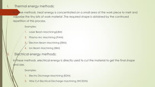
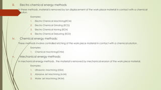
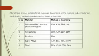
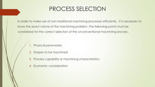
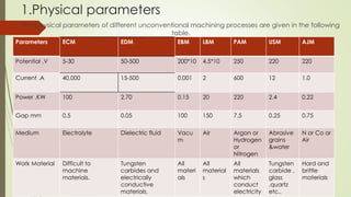
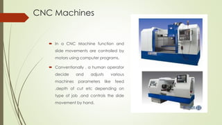
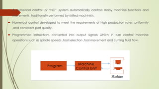
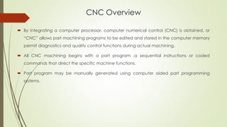
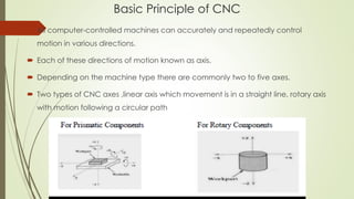
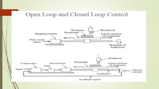
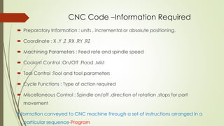
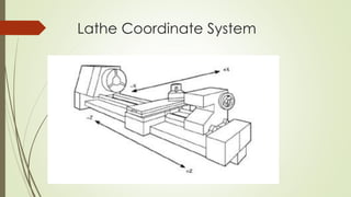
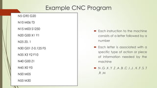
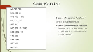
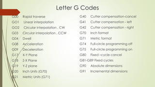
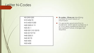
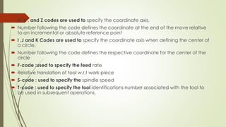
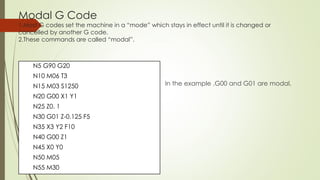
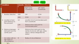
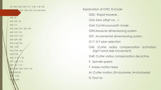
The document discusses conventional and unconventional machining processes. Conventional machining involves direct contact between the tool and workpiece and removal of metal through chip formation, which produces chips as waste. Unconventional processes do not require direct contact and instead use various forms of energy like thermal, electrical or electrochemical to remove metal. Common unconventional processes described include EDM, ECM, laser beam machining and water jet machining. The document also covers CNC machines and how part programs control automated machining through coded G and M commands.
An **unconventional machining process** (or **non-traditional machining process**) is a special type of **machining process**in which there is no direct contact between the tool and the workpiece
UNCONVENTIONAL MACHINING PROCESS CLASSIFICATION-MECHANICAL ENERGY METHODS-ELECTRICAL ENERGY METHODS-CHEMICAL ENERGY METHODS-ELECTRO CHEMICAL ENERGY METHODS-THERMALENERGY METHODS.
Democratizing Fuzzing at Scale by Abhishek Aryaabh.arya
Presented at NUS: Fuzzing and Software Security Summer School 2024
This keynote talks about the democratization of fuzzing at scale, highlighting the collaboration between open source communities, academia, and industry to advance the field of fuzzing. It delves into the history of fuzzing, the development of scalable fuzzing platforms, and the empowerment of community-driven research. The talk will further discuss recent advancements leveraging AI/ML and offer insights into the future evolution of the fuzzing landscape.
About
Indigenized remote control interface card suitable for MAFI system CCR equipment. Compatible for IDM8000 CCR. Backplane mounted serial and TCP/Ethernet communication module for CCR remote access. IDM 8000 CCR remote control on serial and TCP protocol.
• Remote control: Parallel or serial interface.
• Compatible with MAFI CCR system.
• Compatible with IDM8000 CCR.
• Compatible with Backplane mount serial communication.
• Compatible with commercial and Defence aviation CCR system.
• Remote control system for accessing CCR and allied system over serial or TCP.
• Indigenized local Support/presence in India.
• Easy in configuration using DIP switches.
Technical Specifications
Indigenized remote control interface card suitable for MAFI system CCR equipment. Compatible for IDM8000 CCR. Backplane mounted serial and TCP/Ethernet communication module for CCR remote access. IDM 8000 CCR remote control on serial and TCP protocol.
Key Features
Indigenized remote control interface card suitable for MAFI system CCR equipment. Compatible for IDM8000 CCR. Backplane mounted serial and TCP/Ethernet communication module for CCR remote access. IDM 8000 CCR remote control on serial and TCP protocol.
• Remote control: Parallel or serial interface
• Compatible with MAFI CCR system
• Copatiable with IDM8000 CCR
• Compatible with Backplane mount serial communication.
• Compatible with commercial and Defence aviation CCR system.
• Remote control system for accessing CCR and allied system over serial or TCP.
• Indigenized local Support/presence in India.
Application
• Remote control: Parallel or serial interface.
• Compatible with MAFI CCR system.
• Compatible with IDM8000 CCR.
• Compatible with Backplane mount serial communication.
• Compatible with commercial and Defence aviation CCR system.
• Remote control system for accessing CCR and allied system over serial or TCP.
• Indigenized local Support/presence in India.
• Easy in configuration using DIP switches.
Water scarcity is the lack of fresh water resources to meet the standard water demand. There are two type of water scarcity. One is physical. The other is economic water scarcity.
Sachpazis:Terzaghi Bearing Capacity Estimation in simple terms with Calculati...Dr.Costas Sachpazis
Terzaghi's soil bearing capacity theory, developed by Karl Terzaghi, is a fundamental principle in geotechnical engineering used to determine the bearing capacity of shallow foundations. This theory provides a method to calculate the ultimate bearing capacity of soil, which is the maximum load per unit area that the soil can support without undergoing shear failure. The Calculation HTML Code included.
Explore the innovative world of trenchless pipe repair with our comprehensive guide, "The Benefits and Techniques of Trenchless Pipe Repair." This document delves into the modern methods of repairing underground pipes without the need for extensive excavation, highlighting the numerous advantages and the latest techniques used in the industry.
Learn about the cost savings, reduced environmental impact, and minimal disruption associated with trenchless technology. Discover detailed explanations of popular techniques such as pipe bursting, cured-in-place pipe (CIPP) lining, and directional drilling. Understand how these methods can be applied to various types of infrastructure, from residential plumbing to large-scale municipal systems.
Ideal for homeowners, contractors, engineers, and anyone interested in modern plumbing solutions, this guide provides valuable insights into why trenchless pipe repair is becoming the preferred choice for pipe rehabilitation. Stay informed about the latest advancements and best practices in the field.
Overview of the fundamental roles in Hydropower generation and the components involved in wider Electrical Engineering.
This paper presents the design and construction of hydroelectric dams from the hydrologist’s survey of the valley before construction, all aspects and involved disciplines, fluid dynamics, structural engineering, generation and mains frequency regulation to the very transmission of power through the network in the United Kingdom.
Author: Robbie Edward Sayers
Collaborators and co editors: Charlie Sims and Connor Healey.
(C) 2024 Robbie E. Sayers
Cosmetic shop management system project report.pdfKamal Acharya
Buying new cosmetic products is difficult. It can even be scary for those who have sensitive skin and are prone to skin trouble. The information needed to alleviate this problem is on the back of each product, but it's thought to interpret those ingredient lists unless you have a background in chemistry.
Instead of buying and hoping for the best, we can use data science to help us predict which products may be good fits for us. It includes various function programs to do the above mentioned tasks.
Data file handling has been effectively used in the program.
The automated cosmetic shop management system should deal with the automation of general workflow and administration process of the shop. The main processes of the system focus on customer's request where the system is able to search the most appropriate products and deliver it to the customers. It should help the employees to quickly identify the list of cosmetic product that have reached the minimum quantity and also keep a track of expired date for each cosmetic product. It should help the employees to find the rack number in which the product is placed.It is also Faster and more efficient way.
Hybrid optimization of pumped hydro system and solar- Engr. Abdul-Azeez.pdffxintegritypublishin
Advancements in technology unveil a myriad of electrical and electronic breakthroughs geared towards efficiently harnessing limited resources to meet human energy demands. The optimization of hybrid solar PV panels and pumped hydro energy supply systems plays a pivotal role in utilizing natural resources effectively. This initiative not only benefits humanity but also fosters environmental sustainability. The study investigated the design optimization of these hybrid systems, focusing on understanding solar radiation patterns, identifying geographical influences on solar radiation, formulating a mathematical model for system optimization, and determining the optimal configuration of PV panels and pumped hydro storage. Through a comparative analysis approach and eight weeks of data collection, the study addressed key research questions related to solar radiation patterns and optimal system design. The findings highlighted regions with heightened solar radiation levels, showcasing substantial potential for power generation and emphasizing the system's efficiency. Optimizing system design significantly boosted power generation, promoted renewable energy utilization, and enhanced energy storage capacity. The study underscored the benefits of optimizing hybrid solar PV panels and pumped hydro energy supply systems for sustainable energy usage. Optimizing the design of solar PV panels and pumped hydro energy supply systems as examined across diverse climatic conditions in a developing country, not only enhances power generation but also improves the integration of renewable energy sources and boosts energy storage capacities, particularly beneficial for less economically prosperous regions. Additionally, the study provides valuable insights for advancing energy research in economically viable areas. Recommendations included conducting site-specific assessments, utilizing advanced modeling tools, implementing regular maintenance protocols, and enhancing communication among system components.
Saudi Arabia stands as a titan in the global energy landscape, renowned for its abundant oil and gas resources. It's the largest exporter of petroleum and holds some of the world's most significant reserves. Let's delve into the top 10 oil and gas projects shaping Saudi Arabia's energy future in 2024.
2. CONVENTIONAL MACHINING PROCESSES
In conventional machining process , metal is removed
by using some sort of tool which is harder than the work
piece and it is subjected to wear . In this process ,tool
and work piece are in direct contact with each other .
In other words , the conventional machining processes
involve removal of metal by compression shear chip
formation .
3. DEMERITS OF CONVENTIONAL MACHINING PROCESSES
i. In conventional machining , metal is removed by chip formation which is an expensive
and difficult process .
ii. Chips produced during this process are unwanted by-products.
iii. Removal of these chips and their disposal and recycling is a very tedious procedure ,
involving energy and money .
iv. Very large cutting forces are involved in this process . So , proper holding of the work
piece is most important .
v. Due to the large cutting forces and large amount of heat generated between the tool
and the work piece interface , undesirable deformation and residual stresses are
developed in the work piece .
vi. It is not possible to produce chips by conventional machining process for delicate
components like semi conductor .
4. UNCONVENTIONAL MANUFACTURING PROCESSES
Unconventional manufacturing processes can be divided into the following two categories .
1. Unconventional machining processes (UMP) (or) Non-Traditional machining processes (NTMP)
2. Unconventional forming processes
UNCONVENTIONAL MACHINING PROCESSES
The Unconventional machining process do not employ a conventional or traditional tool for metal
removal ,instead ,they directly utilize some form of energy for metal machining.
In this process , there is no direct physical contact between the tool and the workpiece. Therefore,
the tool material need not be harder than the workpiece material as in conventional machining.
UNCONVENTIONAL FORMING PROCESSES
In conventional forming processes ,the metals are formed through the released and application of
large amounts of energy in a very short time interval .
5. NEEDS FOR UNCONVENTIONAL MACHINING
PROCESSES
A harder and difficult to machine materials such as carbides , stainless steel ,
nitralloy , hastalloy and many other high strength temperature resistant alloys
find wide application in aerospace and nuclear engineering industries. Many
of these materials also find application in other industries , owing to their high
strength to weight radio , hardness and heat resisting qualities. For such
materials, the conventional edged tool machining is highly uneconomical and
the degree accuracy and surface finish attainable are poor . The
unconventional machining processes have been developed to over come all
these difficulties.
6. CLASSIFICATION OF UNCONVENTIONAL MACHING
PROCESSES
Unconventional machining processes are classified as follows:
a) Based on the type of energy required to shape the material
i. Thermal energy methods
ii. Electrical energy methods
iii. Electro chemical energy methods
iv. Chemical energy methods
v. Mechanical energy methods
b) Based on the mechanism involved in the process
i. Erosion
ii. Ionic dissolution
iii. Vaporisation
7. c. Source of energy required for material removal
i. Hydrostatic pressure
ii. High current density
iii. High voltage
iv. Ionised material
d) Medium of transfer of energies
i. High voltage particles
ii. Electrolyte
iii. Electron
iv. Hot gases
8. i. Thermal energy methods:
In these methods ,heat energy is concentrated on a small area of the work piece to melt and
vaporize the tiny bits of work material .The required shape is obtained by the continued
repetition of this process.
Examples:
1. Laser Beam Machining(LBM)
2. Plasma Arc Machining (PAM)
3. Electron Beam Machining (EBM)
4. Ion Beam Machining (IBM)
ii. Electrical energy methods:
In these methods ,electrical energy is directly used to cut the material to get the final shape
and size.
Examples:
1. Electro Discharge Machining (EDM)
2. Wire Cut Electrical Discharge machining (WCEDN)
9. iii. Electro chemical energy methods
In these methods ,material is removed by ion displacement of the work place material in contact with a chemical
solution.
Examples:
1. Electro Chemical Machining(ECM)
2. Electro Chemical Grinding (ECG)
3. Electro Chemical Honing (ECH)
4. Electro Chemical Deburring (ECD)
iv. Chemical energy methods:
These methods involve controlled etching of the work piece material in contact with a chemical solution.
Examples:
1. Chemical machining(CHM)
v. Mechanical energy methods:
In mechanical energy methods , the material is removed by mechanical erosion of the work piece material.
Examples:
1. Ultrasonic machining (USM)
2. Abrasive Jet Machining (AJM)
3. Water Jet Machining (WJM)
10. All methods are not suitable for all materials. Depending on the material to be machined
the following methods can be used as shown in the table
S. No Material Method of Machining
1. Nonmetals like ceramics ,
plastics and glass
USM, AJM, EBM ,LBM
2. Refractories USM ,AJM ,EDM ,EBM
3. Titanium EDM
4. Super Alloys AJM ,ECM ,EDM ,PAM
5. Steel ECM ,CHM ,EDM ,PAM
11. PROCESS SELECTION
In order to make use of non-traditional machining processes efficiently , it is necessary to
know the exact nature of the machining problem .The following points must be
considered for the correct selection of the unconventional machining process .
1. Physical parameters
2. Shapes to be machined
3. Process capability or machining characteristics
4. Economic consideration
12. 1.Physical parameters
The physical parameters of different unconventional machining processes are given in the following
table.
Parameters ECM EDM EBM LBM PAM USM AJM
Potential .V 5-30 50-500 200*10 4.5*10 250 220 220
Current .A 40,000 15-500 0.001 2 600 12 1.0
Power ,KW 100 2.70 0.15 20 220 2.4 0.22
Gap mm 0.5 0.05 100 150 7.5 0.25 0.75
Medium Electrolyte Dielectric fluid Vacu
m
Air Argon or
Hydrogen
or
Nitrogen
Abrasive
grains
&water
N or Co or
Air
Work Material Difficult to
machine
materials.
Tungsten
carbides and
electrically
conductive
materials.
All
materi
als
All
material
s
All
materials
which
conduct
electricity
Tungsten
carbide ,
glass
,quartz
etc.,
Hard and
brittle
materials
13. 2.Shapes to be machined
The application of the unconventional machining processes is also influenced by the shape and
size of the work piece to be produced.
For producing micro holes -LBM is best suited.
For producing small holes -EBM is well suited.
For deep holes(L/D>20) and contour machining -ECM is best suited.
For shallow holes -USM and EDM are well suited.
For precision through cavities in work pieces -USM and EDM are best suited.
14. For honing -ECM is well suited.
For etching small portions -ECM and EDM are well suited.
For Grinding -AJM and EDM are best suited.
For deburring -USM and AJM are well suited.
For threading -EDM is best suited.
For clean ,rapid cuts and profiles -PAM is well suited
For shallow pocketing -AJM is well suited.
15. 3.Process capability (or) Machining Characteristics
The machining characteristic scan be analyzed with respect to
1. Metal removal rate obtained
2. Tolerance maintained
3. Surface finish obtained
4. Depth of surface damage
5. Power required for machining
The following table gives the typical values
of the various unconventional machining
characteristics
Process Process
Capability
Metal
removal
(mm)
(MRR)
Surface
Finish
(.,CLA)
Accuracy
(.m)
Specific
power
(kW/c
m/min)
LBM 0.10 0.4 -6.0 25 2700
EBM 0.15 to
40
0.4-6.0 25 450
EDM 15 to 80 0.25 10 1.8
ECM 27 0.2-0.8 50 7.5
PAM 2500 Rough 250 0.90
USM 14 0.2-0.7 7.5 9.0
AJM 0.014 0.5-1.2 50 312.5
16. 4.Process Economy
The economics of the various processes are analyzed by considering the following points
1. Capital cost.
2. Tooling cost.
3. Power requirement.
4. Metal removal rate efficiency
5. Tool consumption
The following table gives the process economy of unconventional machining processes.
Process Capital
Cost
Tooling
and
Fixtures
Power
Requirem
ent
Efficiency Total
consumpt
ion
EDM Medium High Low High High
CHM Medium Low High Medium V.Low
ECM V.High Medium Medium Low V.Low
AJM V.Low Low Low High Low
USM High High High High Medium
EBM High Low Low V.High V.Low
LBM Medium Low V.Low V.High V.Low
PAM V.Low Low V.Low V.Low V.Low
Conventional V.Low Low Low V.Low Low
17. LIMITATIONS OF UNCONVENTIONAL MACHINING
PROCESSES
1. Unconventional machining processes are more expensive.
2. Metal removal rate is slow.
3. AJM ,CHM ,PAM ,and EBM are not commercially economical processes.
ADVANTAGES OF UNCONVENTIONAL MACHINING PROCESSES
1. It increases productivity.
2. It reduces number of rejected components.
3. Close tolerance is possible.
4. The tool material need not be harder than work piece material as in conventional
machining.
5. Harder and difficult to machine materials can be machined by this processes.
6. The machined surface do not have any residual stresses.
18. MACHINING-CENTRE LATHE
A centre lathe is also called an engine lathe or simply a lathe. It is one of the commonest
and oldest machine tools.
It is also one of the most versatile and widely used machines. Its main function is
production of cylindrical profiles.
19. ▪ The main parts of a centre lathe are:
Machine bed
Headstock
Tailstock
Carriage
▪ Many different kind of operations are carried out on lathes such as:
Turning ,facing ,lathe
Taper turning ,profile turning or form turning ,parting
Boring ,Threading ,Knurling.
20. Milling is a machining process which is performed with a rotary cutter with several cutting
edges arranged on the perihery of the cutter.
This process is used to generate flat surfaces or curved profile and many other intricate shapes
with great accuracy and having very good surface finish.
Generally ,there are two types of milling processes. These are called
a)Up milling or conventional milling process, and
b)Down milling or climb milling process.
In up milling ,the direction of rotation of milling cutter and the direction of work piece feed
are opposite to each other;
In up milling , the thickness of chip at the start is nil and is maximum when the cutting teeth
leave the surface of the work piece.
In up milling ,the cutting teeth try to uproot and lift the work piece from the machine table.
In down milling ,the direction of rotation of milling cutter and the direction of work piece feed
move in the same direction at the point of contact of the cutter and the workpiece.
21.
22. The milling process is broadly classified into peripheral milling and face milling.
In peripheral milling ,the cutting edges are primarily on the circumference or periphey of the
milling cutter and the milled surface is generally parallel to cutter axis.
23. In face milling ,although the cutting edges or provided on the faces as well as the periphery
of the cutter ,the surface generated is parallel to the face of the cutter and is perpendicular
to the cutter axis.
24. Peripheral milling is adopted for the following machining operations:
Slab milling to produce flash surfaces.
Slot milling to produce precision slots.
Side and face milling to machine adjacent horizontal and vertical surfaces simultaneously.
Form milling to produce prismatic shape of any form ,e.g., involute form in gear cutting .
Straddle milling to machine two parallel vertical faces.
Gang milling to machine several surfaces simultaneously with a set of cutters.
Face milling is a combination of up cut and down cut milling operation.
In face milling ,the position of the cutter with respect to the workpiece is of considerable
significance.
Either the cutter may be symmetrically placed on the workpiece, or it may be
asymmetrically placed , offset slightly towards the entry side or it may be asymmetric ,offset
slightly towards the exit side
25.
26. CNC Machines
In a CNC Machine function and
slide movements are controlled by
motors using computer programs.
Conventionally , a human operator
decide and adjusts various
machines parameters like feed
,depth of cut etc depending on
type of job ,and controls the slide
movement by hand.
27. Types of Milling Machine
❖ Mills and Machining Centres
❖ Lathes and Turning Centres
❖ Drilling Machines
❖ EDM sinker and wire cut Machines
❖ Flame and Laser –cutting Machines
❖ Water Jet Profilers
31. A numerical control ,or “NC” ,system automatically controls many machine functions and
movements traditionally performed by skilled machinists.
Numerical control developed to meet the requirements of high production rates ,uniformity
,and consistent part quality.
Programmed instructions converted into output signals which in turn control machine
operations such as spindle speeds ,tool selection ,tool movement and cutting fluid flow.
32. CNC Overview
By integrating a computer processor, computer numerical control (CNC) is obtained, or
“CNC” allows part machining programs to be edited and stored in the computer memory
permit diagnostics and quality control functions during actual machining.
All CNC machining begins with a part program ,a sequential instructions or coded
commands that direct the specific machine functions.
Part program may be manually generated using computer aided part programming
systems.
33. Basic Principle of CNC
All computer-controlled machines can accurately and repeatedly control
motion in various directions.
Each of these directions of motion known as axis.
Depending on the machine type there are commonly two to five axes.
Two types of CNC axes ,linear axis which movement is in a straight line, rotary axis
with motion following a circular path
34.
35. CNC Code –Information Required
Preparatory Information : units , incremental or absolute positioning.
Coordinate : X ,Y ,Z ,RX ,RY ,RZ
Machining Parameters : Feed rate and spindle speed
Coolant Control :On/Off ,Flood ,Mist
Tool Control :Tool and tool parameters
Cycle Functions : Type of action required
Miscellaneous Control : Spindle on/off ,direction of rotation ,stops for part
movement
Information conveyed to CNC machine through a set of instructions arranged in a
particular sequence-Program
43. Example CNC Program
N5 G90 G20
N10 M06 T3
N15 M03 S1250
N20 G00 X1 Y1
N25 Z0. 1
N30 G01 Z-0.125 F5
N35 X3 Y2 F10
N40 G00 Z1
N45 X0 Y0
N50 M05
N55 M30
Each instruction to the machine
consists of a letter followed by a
number
Each letter is associated with a
specific type of action or piece
of information needed by the
machine
N ,G ,X ,Y ,Z ,A ,B ,C ,I ,J , K ,F ,S ,T
,R ,M
45. Letter G Codes
G00 Rapid traverse
GO1 Linear interpolation
GO2 Circular interpolation , CW
G03 Circular interpolation , CCW
G04 Dwell
G08 Acceleration
G09 Deceleration
G17 X-Y Plane
G18 Z-X Plane
G19 Y-Z plane
G20 Inch Units (G70)
G21 Metric Units (G71)
G40 Cutter compensation-cancel
G41 Cutter compensation - left
G42 Cutter compensation - right
G70 Inch format
G71 Metric format
G74 Full-circle programming off
G75 Full-circle programming on
G80 Fixed –cycle cancel
G81-G89 Fixed cycles
G90 Absolute dimensions
G91 Incremental dimensions
46. Letter M-Codes
M00 Program stop
M01 Optional program stop
M02 Program end
M03 Spindle on clockwise
M04 Spindle on counterclockwise
M05 Spindle stop
M06 Tool change
M08 Coolant on
M09 Coolant off
M10 Clamps on
M11 Clamps off
M30 Program stop ,reset to start
47. Letter N-Codes
N5 G90 G20
N10 M06 T3
N15 M03 S1250
N20 G00 X1 Y1
N25 Z0. 1
N30 G01 Z-0.125 F5
N35 X3 Y2 F10
N40 G00 Z1
N45 X0 Y0
N50 M05
N55 M30
N-codes : Gives an identifying
number for each block of
information
it is generally good practice to
increment each block number by 5
or 10 to allow additional blocks to
be inserted if future changes are
required.
48. X ,Y , and Z codes are used to specify the coordinate axis.
Number following the code defines the coordinate at the end of the move relative
to an incremental or absolute reference point
I ,J and K Codes are used to specify the coordinate axis when defining the center of
a circle.
Number following the code defines the respective coordinate for the center of the
circle
F-code :used to specify the feed rate
Relative translation of tool w.r.t work piece
S-code : used to specify the spindle speed
T-code : used to specify the tool identifications number associated with the tool to
be used in subsequent operations.
49. Modal G Code
1.Most G codes set the machine in a “mode” which stays in effect until it is changed or
cancelled by another G code.
2.These commands are called “modal”.
N5 G90 G20
N10 M06 T3
N15 M03 S1250
N20 G00 X1 Y1
N25 Z0. 1
N30 G01 Z-0.125 F5
N35 X3 Y2 F10
N40 G00 Z1
N45 X0 Y0
N50 M05
N55 M30
In the example ,G00 and G01 are modal.
50. Conditions Instructio
n
Meaning
Right hand
Coordinate
Left hand
Coordinate
1 Rotation direction G02 CW CCW
G03 CCW CW
2 Location of end
point Distance to
the end point
X,Z Location X,Z of commanded point
from coordinate
U,W Distance from start point to
commanded point
3 Distance between
start point and the
center point
I,K Distance from start point to the
center of and arc with sign, radius
value ( I always designates the
radius)
Arc radius with no
sign radius of
circumference
R Radius of circumference