Download to read offline
![The Different On Performance between LTE FDD and LTE TDD Eng. Dalia ABDALLA Omer
DOI: 10.9790/2834-102196100 www.iosrjournals.org 100 | Page
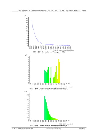
FDD – 2100 Covered area / Carrier-to-noise ratio (UL)
FDD – 2100 Covered area / Carrier-to-noise ratio (DL)
III. Conclusion
This paper demonstrates that the main difference between LTE-FDD and LTE-TDD is how they divide
the signal channel to provide paths for both uploading (mobile transmit) and downloading (base-station
transmit), Hence the preference for one over the other is essentially depends on the purpose of using the system,
therefore:
If the goal of the system is the coverage, it's preferable to work with TDD.
If the goal of the system is the Throughput, it's preferable to work with FDD.
The Carrier-to-noise ratio is the same in both TDD and FDD.
References
[1]. Progress In Electromagnetics Research Symposium Proceedings, KL, MALAYSIA, March 27-30, 2012 1467 LTE-FDD and LTE-
TDD for Cellular Communications A. Z. Yonis, M. F. L. Abdullah1, and M. F. Ghanim Faculty of Electrical and Electronic
Engineering, Department of Communication Engineering University of Tun Hussein Onn Malaysia, Johor, MalaysiaComputer
Engineering Department, College of Engineering, University of Mosul, Mosul, Iraq
agilent techonology Testing LTE FDD and TDD Performance http://cp.literature.agilent.com/litweb/pdf/5990-5657EN.pdf
[2]. Internet access performance in LTE TDD Riikka Susitaival1, Henning Wiemann3, Jessica Östergaard2, Anna Larmo1 Ericsson
Research 1Finland, 2Sweden, 3Germany
LTE TDD: The preferred choice for mobile broadband in unpaired bands Authored by Claus Hetting & Stefan Stanislawski, Ventura
Team LLP march 2010
[3]. TD-LTE and FDD-LTE A Basic Comparison Prepared by: Date: Document: Angel Ivanov 12 Jan 2012 NT11-1036 © Ascom (2012)
[4]. Using LTE to deliver mobile broadband applications that contribute to society Manuel Vexler, CMO IMS/NGN October 16, 2012
HUAWEI TECHNOLOGIES
[5]. Coverage and Capacity Analysis of LTE Radio Network Planning considering Dhaka City Nafiz Imtiaz Bin Hamid. Mohammad T.
Kawser Md. Ashraful Hoque Department of EEE Islamic University of Technology Gazipur-1704, Bangladesh.
km²
0
0.9
1.8
2.7
3.6
4.5
5.4
6.3
7.2
8.1
9
9.9
10.8
-20
-18
-16
-13.6
-11.6
-9.6
-7.6
-5.6
-3.2
-1.2
0.8
2.8
4.8
7.2
9.2
11.2
13.2
15.2
17.6
19.6
21.6
23.6
25.6
28
30
32
PUSCH & PUCCH C/(I+N) Level (UL) (dB)
km²
0
0.56
1.12
1.68
2.24
2.8
3.36
3.92
4.48
5.04
5.6
6.16
6.72
-20
-18
-16
-13.6
-11.6
-9.6
-7.6
-5.6
-3.2
-1.2
0.8
2.8
4.8
7.2
9.2
11.2
13.2
15.2
17.6
19.6
21.6
23.6
25.6
28
30
32
PDSCH C/(I+N) Level (DL) (dB)](https://image.slidesharecdn.com/n0102196100-160729100720/85/N0102196100-5-320.jpg)

This document compares LTE networks using frequency division duplexing (FDD) versus time division duplexing (TDD). FDD uses separate frequencies for downlink and uplink, while TDD uses timesharing of a single frequency between downlink and uplink. TDD can operate with unpaired spectrum and dynamically allocate bandwidth between downlink and uplink. FDD generally provides better support for symmetric traffic like voice calls but requires paired spectrum. The document presents simulation results showing the coverage area and throughput of FDD and TDD LTE networks. It concludes that the preferred duplexing method depends on the intended use and characteristics of the network and traffic.