This document contains a presentation on LTE TDD given by Bong Youl Cho of Nokia Solutions and Networks. The presentation provides an overview of LTE TDD technology, including comparisons to WiMAX and 3G TDD, details on TDD configurations and carrier aggregation, enhancements in Release 12 and beyond, and the growth of LTE TDD deployment by major operators worldwide. It aims to demonstrate that LTE TDD and FDD can be highly integrated to provide "the best LTE" network through global roaming and seamless handovers between the technologies.
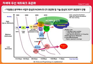
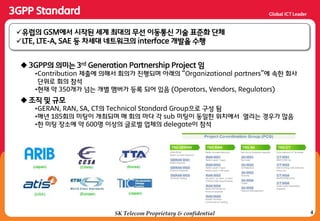
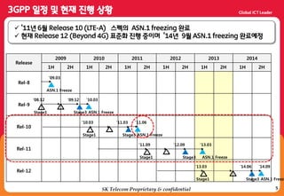
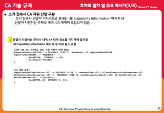
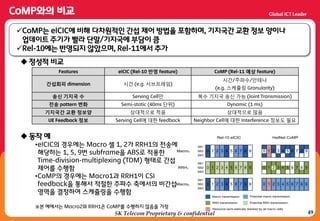
![TTA LTE Standards/Technology Training
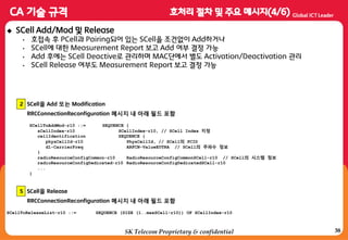
9 © 2013 Nokia Solutions and Networks. All rights reserved.
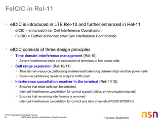
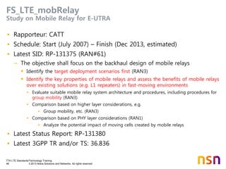
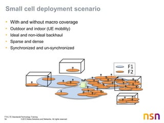
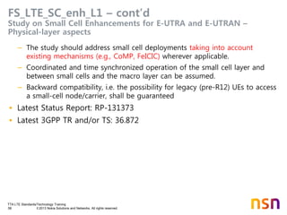
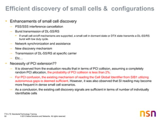
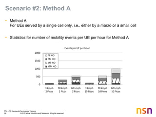
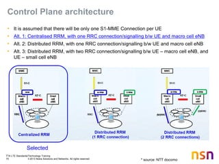
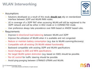
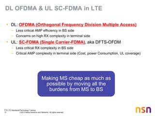
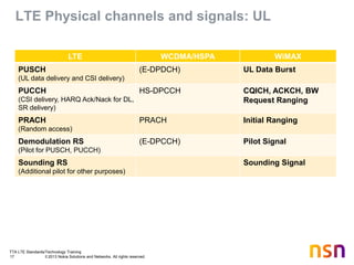
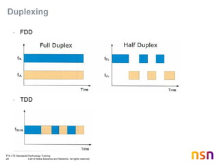
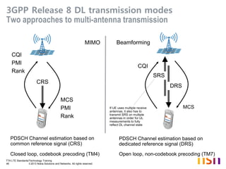
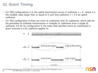
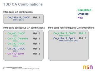
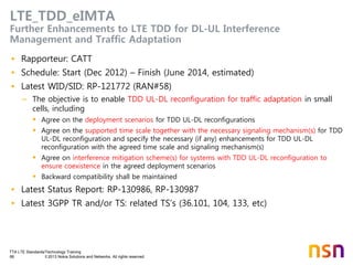
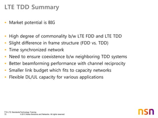
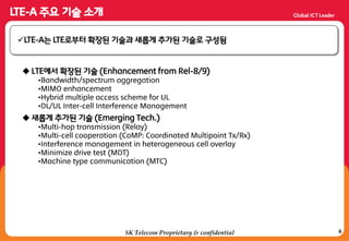
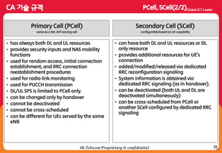
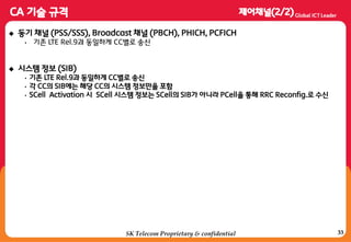
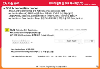
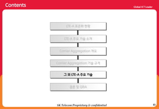
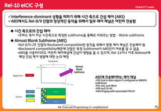
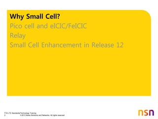
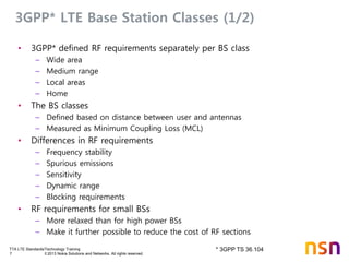
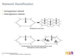
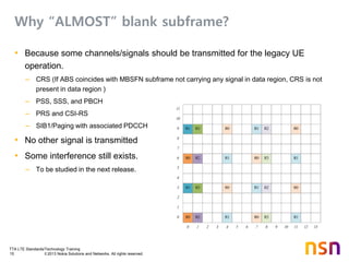
LTE TDD DL/UL Config
Brings Higher DL PDR & Flexibility
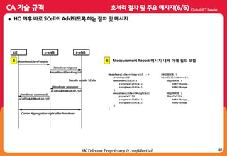
Peak data rate
[Mbps]
Similar Spectrum Efficiency
with FDD LTE
DL/UL(3:1) to DL service
up to 110Mbps](https://image.slidesharecdn.com/lte-150627102311-lva1-app6891/85/Lte-aa-e-a-u-a-9-320.jpg)
![TTA LTE Standards/Technology Training
35 © 2013 Nokia Solutions and Networks. All rights reserved.
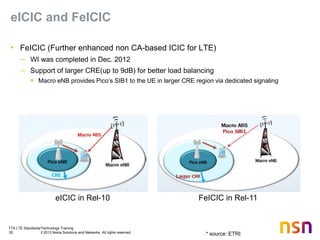
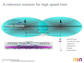
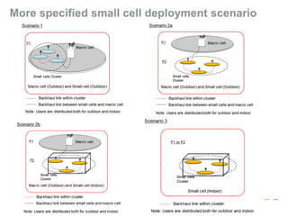
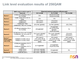
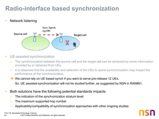
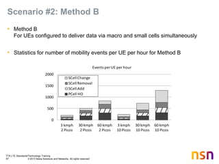
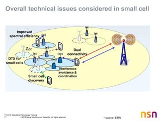
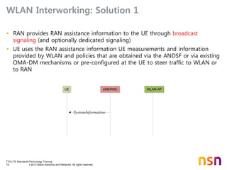
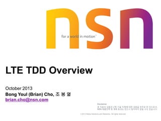
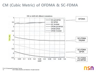
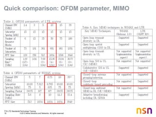
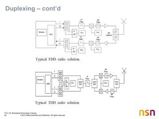
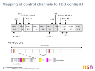
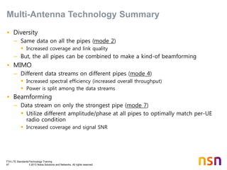
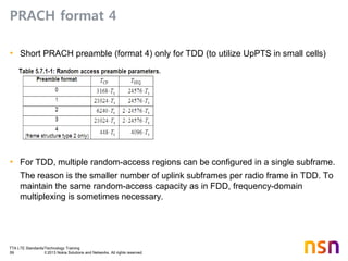
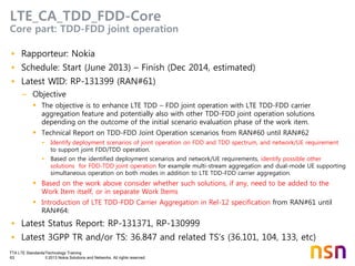
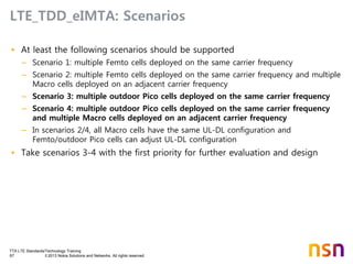
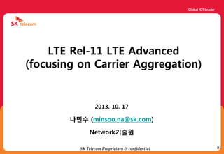
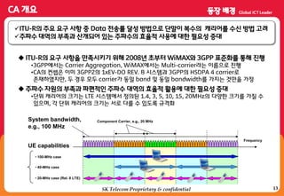
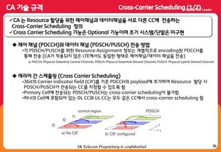
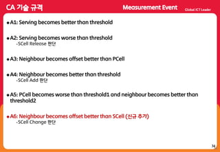
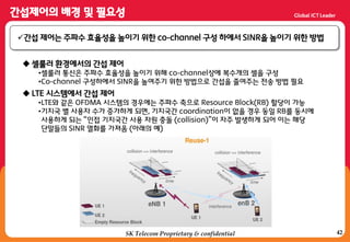
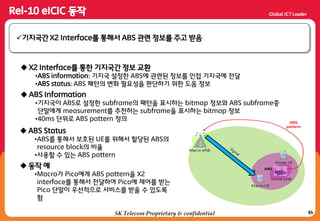
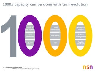
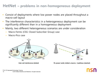
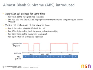
System Information
• Master information block (MIB) includes the following information:
– Downlink cell bandwidth [4 bit]
– System Frame Number (SFN) except two LBSs
– Etc…
• LTE defines different SIBs:
– SIB1 includes info mainly related to whether an UE is allowed to camp on the cell. This includes info
about the operator(s) and about the cell (e.g. PLMN identity list, tracking area code, cell identity,
minimum required Rx level in the cell, etc), DL-UL subframe configuration in TDD case, and the
scheduling of the remaining SIBs. SIB1 is transmitted every 80ms.
– SIB2 includes info that UEs need in order to be able to access the cell. This includes info about the UL
cell BW, random access parameters, and UL power control parameters. SIBs also includes radio
resource configuration of common channels (RACH, BCCH, PCCH, PRACH, PDSCH, PUSCH,
PUCCH, and SRS).
– SIB3-4 mainly includes info related to cell-reselection.
– SIB5-8 include neighbor-cell-related info. (E-UTRAN, UTRAN, GERAN, cdma2000)
– SIB9 contains a home eNB identifier
– SIB10/11 contains ETWS (Earthquake and Tsunami Warning System) notification
– SIB12: CMAS
– SIB13: eMBMS
– More to be added
• MIB mapped to PBCH, Other SIBs mapped to PDSCH](https://image.slidesharecdn.com/lte-150627102311-lva1-app6891/85/Lte-aa-e-a-u-a-35-320.jpg)

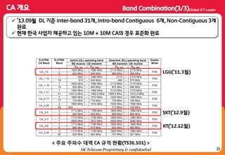
![6
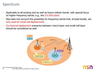
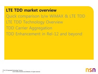
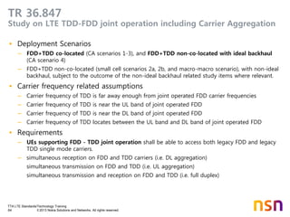
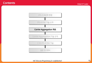
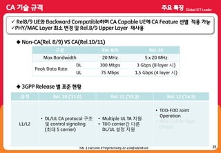
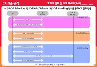
[참고] 3GPP 규격
3GPP 공식 Site에서 누구나 접속 가능 (3GPP Specification Numbering)
LTE, LTE-A 관렦 RAN 규격은 36 Series에서 확인](https://image.slidesharecdn.com/lte-150627102311-lva1-app6891/85/Lte-aa-e-a-u-a-78-320.jpg)
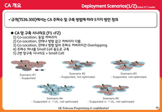
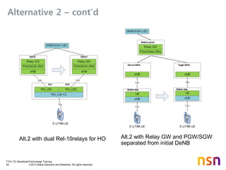
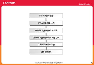
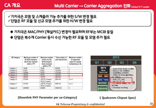
![18
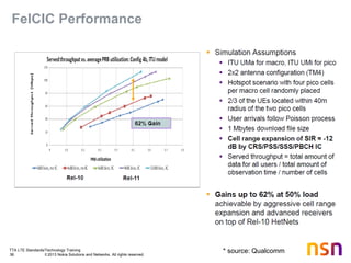
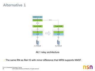
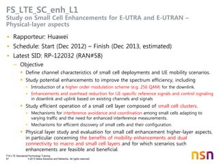
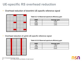
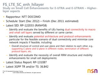
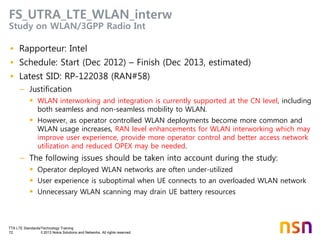
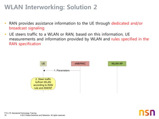
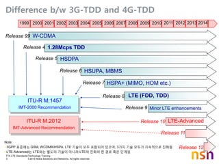
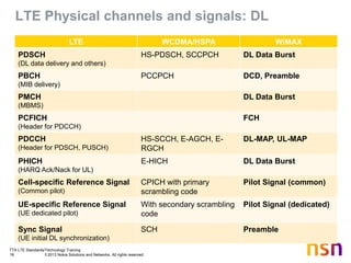
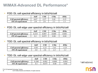
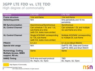
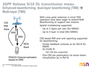
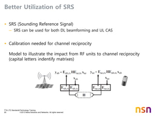
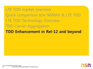
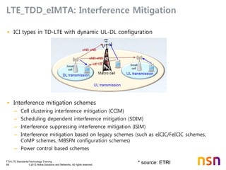
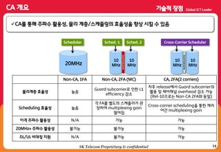
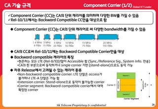
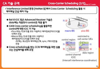
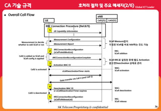
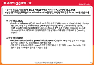
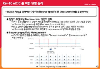
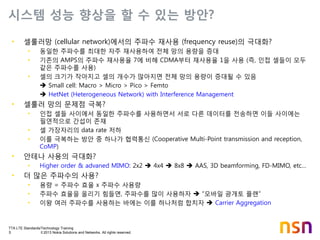
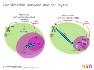
[참고] TS36.300 Annex J.1 CA Deployment Scenarios
1
F1 and F2 cells are co-located and overlaid, providing nearly the
same coverage. Both layers provide sufficient coverage and
mobility can be supported on both layers. Likely scenario is when
F1 and F2 are of the same band.
2
F1 and F2 cells are co-located and overlaid, but F2 has smaller
coverage due to larger path loss. Only F1 provides
sufficient coverage and F2 is used to improve throughput.
Mobility is performed based on F1 coverage. Likely scenario
when F1 and F2 are of different bands. (F1<F2)
3
F1 and F2 cells are co-located but F2 antennas are directed to
the cell boundaries of F1 so that cell edge throughput is
increased. F1 provides sufficient coverage but F2 potentially
has holes, e.g., due to larger path loss. Mobility is based on
F1 coverage. Likely scenario is when F1 and F2 are of
different bands. (F1<F2)
4
F1 provides macro coverage and on F2 Remote Radio Heads
(RRHs) are used to provide throughput at hot spots. Mobility is
performed based on F1 coverage. Likely scenario is when F1 and
F2 are of different bands. (F1<F2)
5
Similar to scenario #2, but frequency selective repeaters are
deployed so that coverage is extended for one of the carrier
frequencies. (F1<F2)
F1 F2
SK Telecom Proprietary & confidential](https://image.slidesharecdn.com/lte-150627102311-lva1-app6891/85/Lte-aa-e-a-u-a-90-320.jpg)
![52SK Telecom Proprietary & confidential
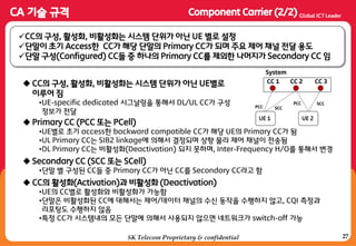
[1]3GPP TR 25.913: "Requirements for Evolved UTRA (E-UTRA) and Evolved UTRAN
(E-UTRAN)".
[2] 3GPP TR 36.913: "Requirements for Further advancements for Evolved UTRA (E-
UTRA) (LTE-Advanced)(Release10)".
[3] 3GPP TR 36.912: ”Feasibility study for Further Advancements for E-UTRA (LTE-
Advanced)”
[4] 3GPP TS 36.101: "User Equipment (UE) radio transmission and reception".
[5] 3GPP TS 36.213: "Evolved Universal Terrestrial Radio Access (E-UTRA); Physical
layer procedures
[6] 3GPP TS36.331: “Evolved Universal Terrestrial Radio Access (E-UTRA); Radio
Resource Control (RRC) protocol specification”](https://image.slidesharecdn.com/lte-150627102311-lva1-app6891/85/Lte-aa-e-a-u-a-124-320.jpg)
![53SK Telecom Proprietary & confidential
[7] :GPP TS:6.:29: “Evolved Univers=l Terrestri=l R=dio A??ess (E-UTRA); Medium Access
Control (MAC) proto?ol spe?ifi?=tion”
[<] :GPP TS :6.299: “Evolved Univers=l Terrestri=l R=dio A??ess (E-UTRA); Physical
channels and modulation
[9] :GPP TS :6.:86: “Evolved Univers=l Terrestri=l R=dio A??ess (E-UTRA); User Equipment
(UE) r=dio =??ess ?=p=>ilities”
[98] :GPP TS :6.:88: “Evolved Univers=l Terrestri=l R=dio A??ess (E-UTRA) and Evolved
Universal Terrestrial Radio Access Network (E-UTRAN); Over=ll des?ription; St=ge 2”](https://image.slidesharecdn.com/lte-150627102311-lva1-app6891/85/Lte-aa-e-a-u-a-125-320.jpg)


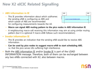
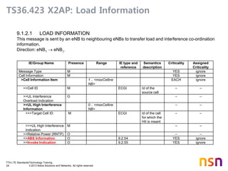
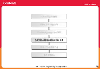
![TTA LTE Standards/Technology Training
25 © 2013 Nokia Solutions and Networks. All rights reserved.
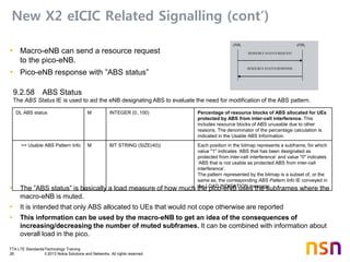
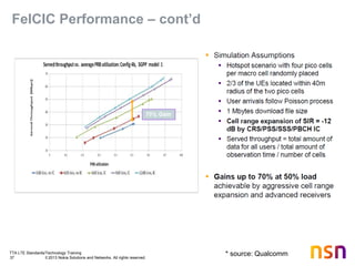
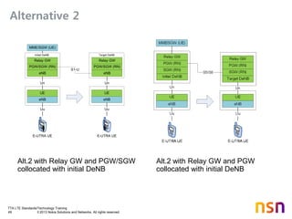
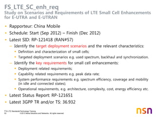
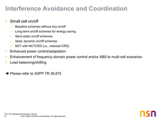
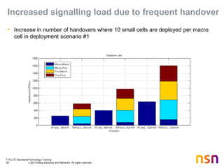
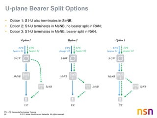
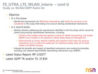
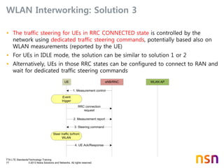
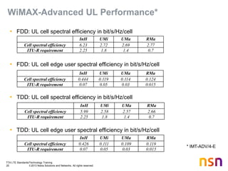
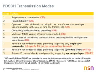
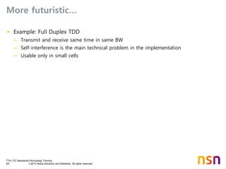
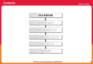
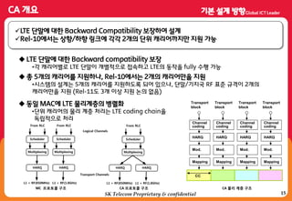
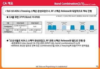
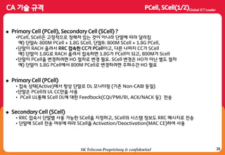
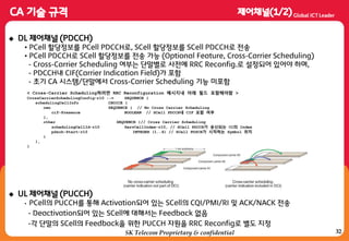
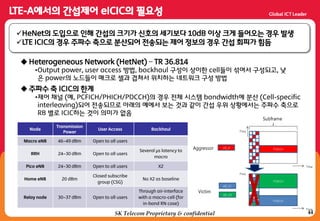
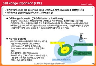
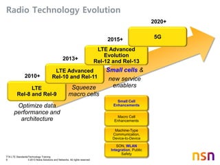
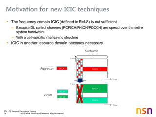
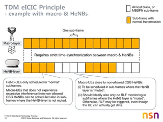
TS36.423 Invoke IE & ABS Information IE
IE/Group Name Presence Range IE type and
reference
Semantics description
CHOICE ABS Information M – –
>FDD – –
>>ABS Pattern Info M BIT STRING
(SIZE(40))
Each position in the bitmap represents a DL
subframe, for which value "1" indicates ‘ABS’
and value "0" indicates ’non ABS’.
The first position of the ABS pattern
corresponds to subframe 0 in a radio frame
where SFN = 0. The ABS pattern is
continuously repeated in all radio frames.
The maximum number of subframes is 40.
>>Number Of Cell-specific
Antenna Ports
M ENUMERATED
(1, 2, 4, …)
P (number of antenna ports for cell-specific
reference signals) defined in TS 36.211 [10]
>>Measurement Subset M BIT STRING
(SIZE(40))
Indicates a subset of the ABS Pattern Info
above, and is used to configure specific
measurements towards the UE.
IE/Group Name Presence Range IE type and
reference
Semantics description
Invoke Indication M ENUMERATED (A
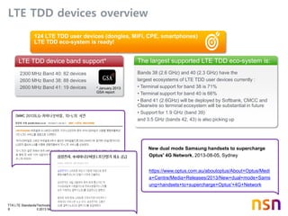
BS Information, …)
–](https://image.slidesharecdn.com/lte-150627102311-lva1-app6891/85/Lte-aa-e-a-u-a-151-320.jpg)