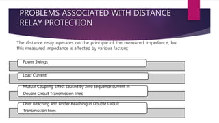
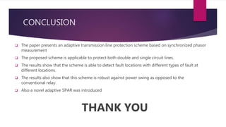
The document discusses the design of a phasor measurement unit (PMU) based transmission line protection scheme that addresses the challenges of traditional distance relaying protection methods. It highlights the benefits of using synchronized measurement data for real-time fault detection and an adaptive single pole auto-recloser (SPAR) to differentiate between transient and permanent faults. The proposed scheme demonstrates high accuracy in determining fault locations under various conditions and is robust against power swings, outperforming conventional methods.


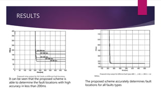
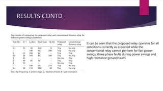


![protection of transmission lines[distance relay protection scheme]](https://cdn.slidesharecdn.com/ss_thumbnails/os-exe3-23-may2011-sr-i-776s21tr-lineprotection-120425095503-phpapp02-thumbnail.jpg?width=640&height=640&fit=bounds)


