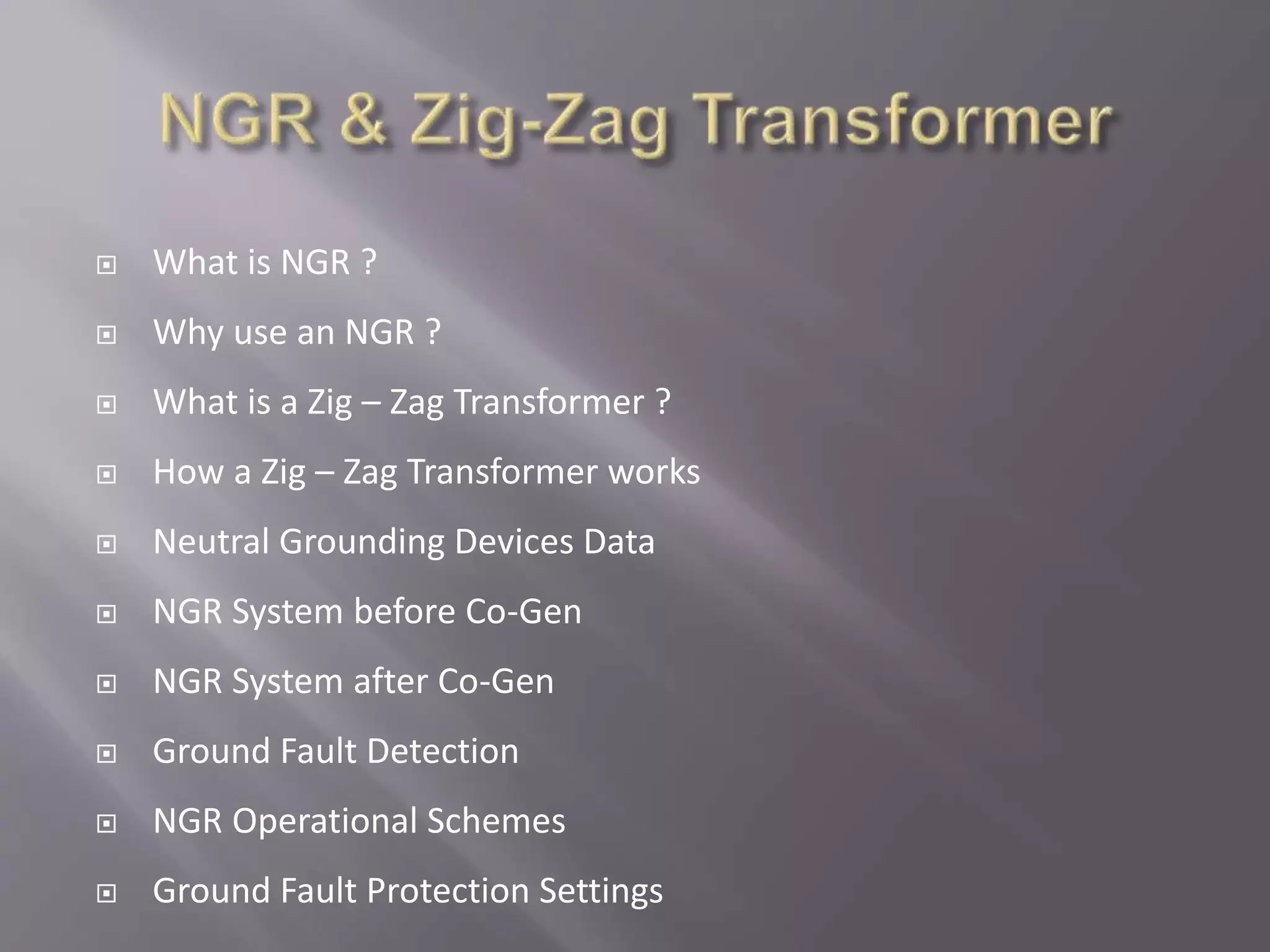
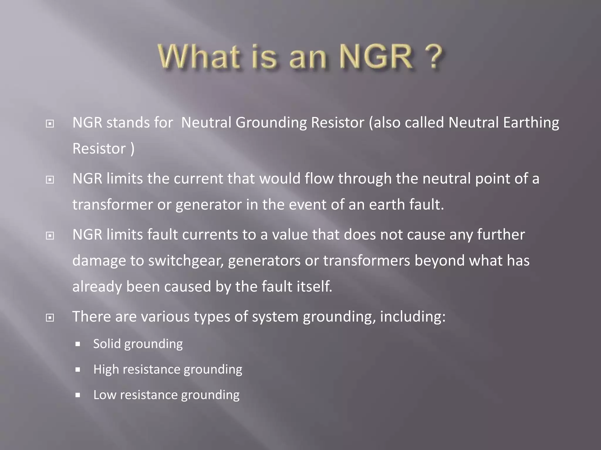
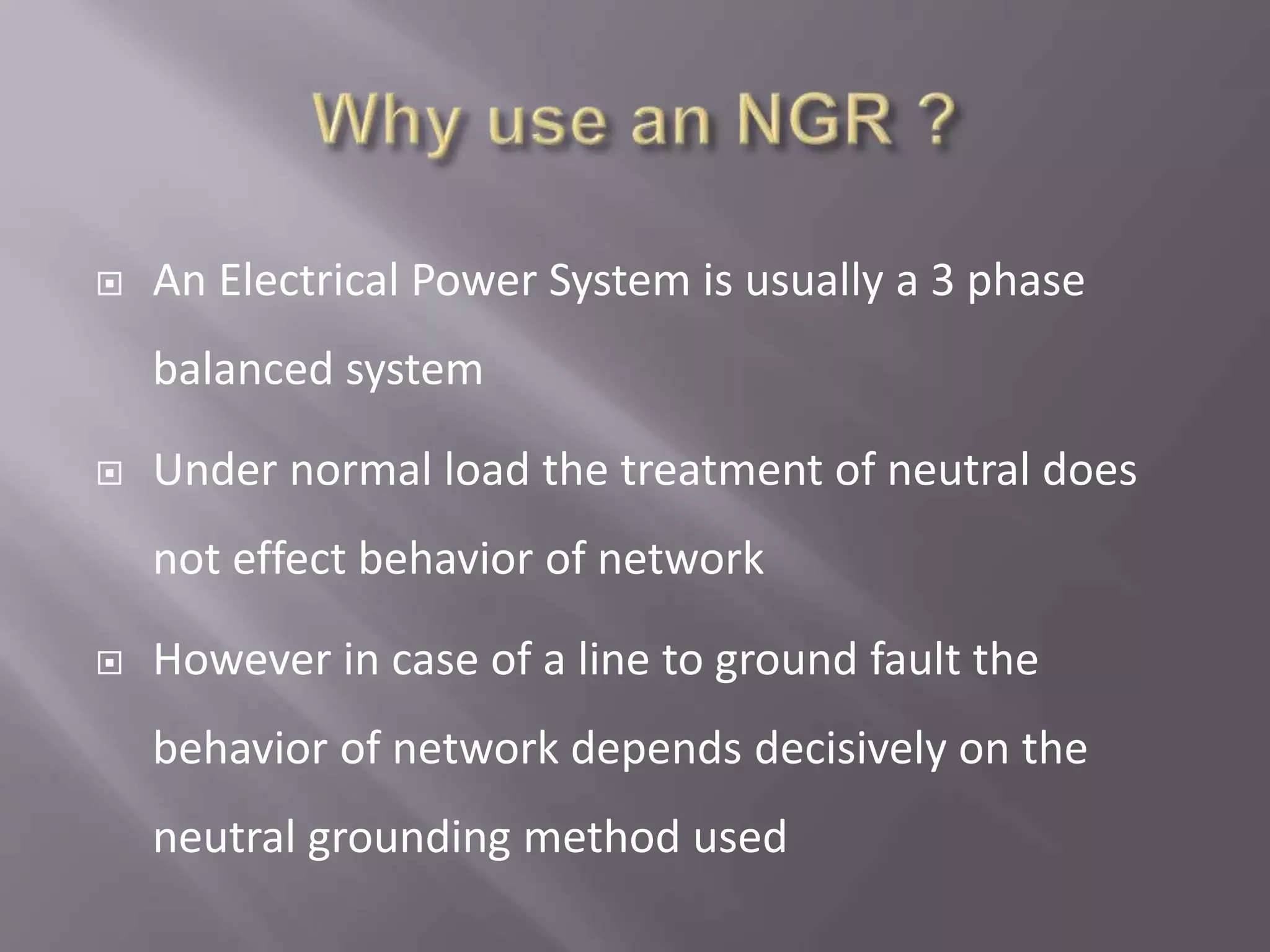
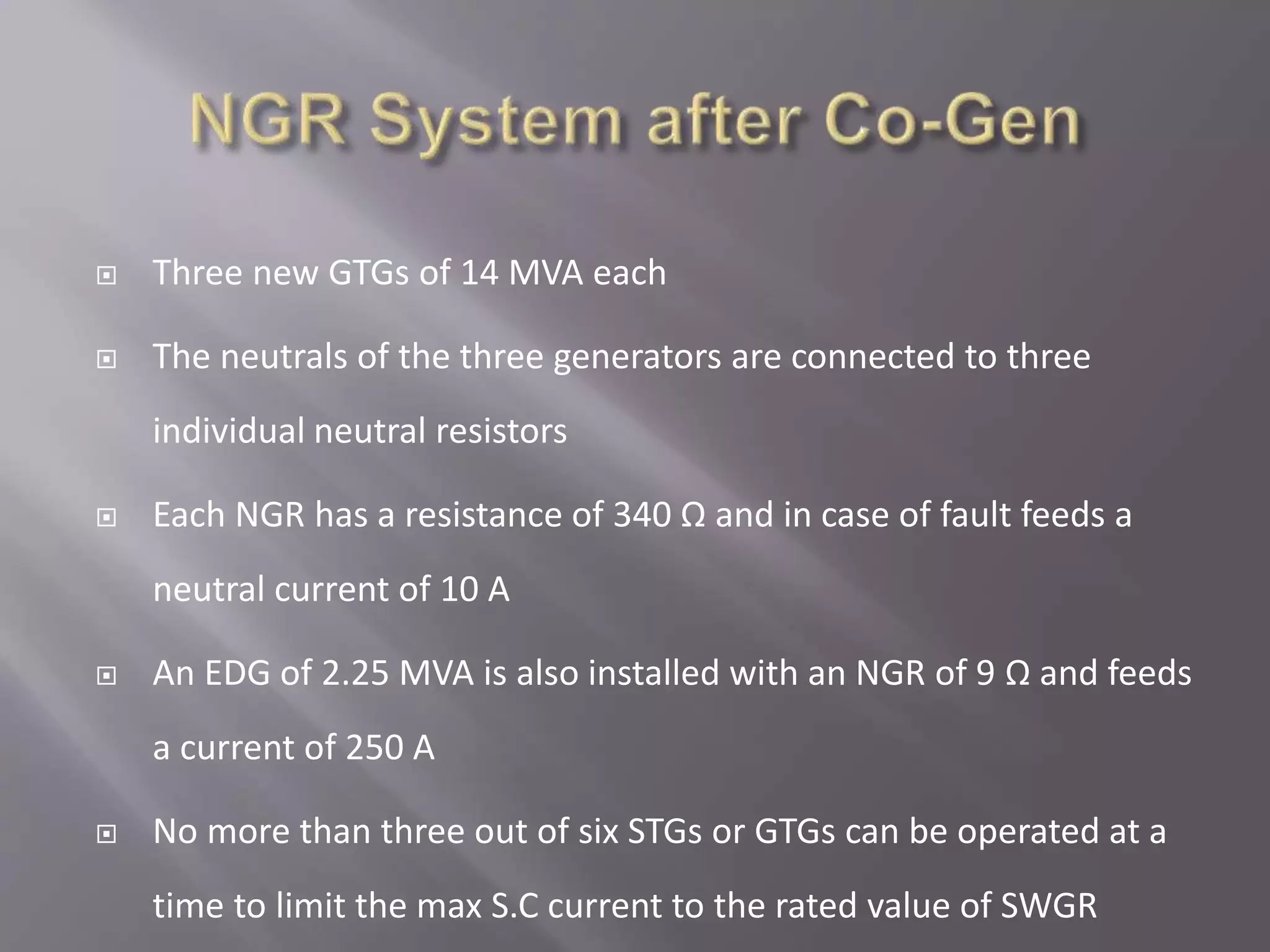
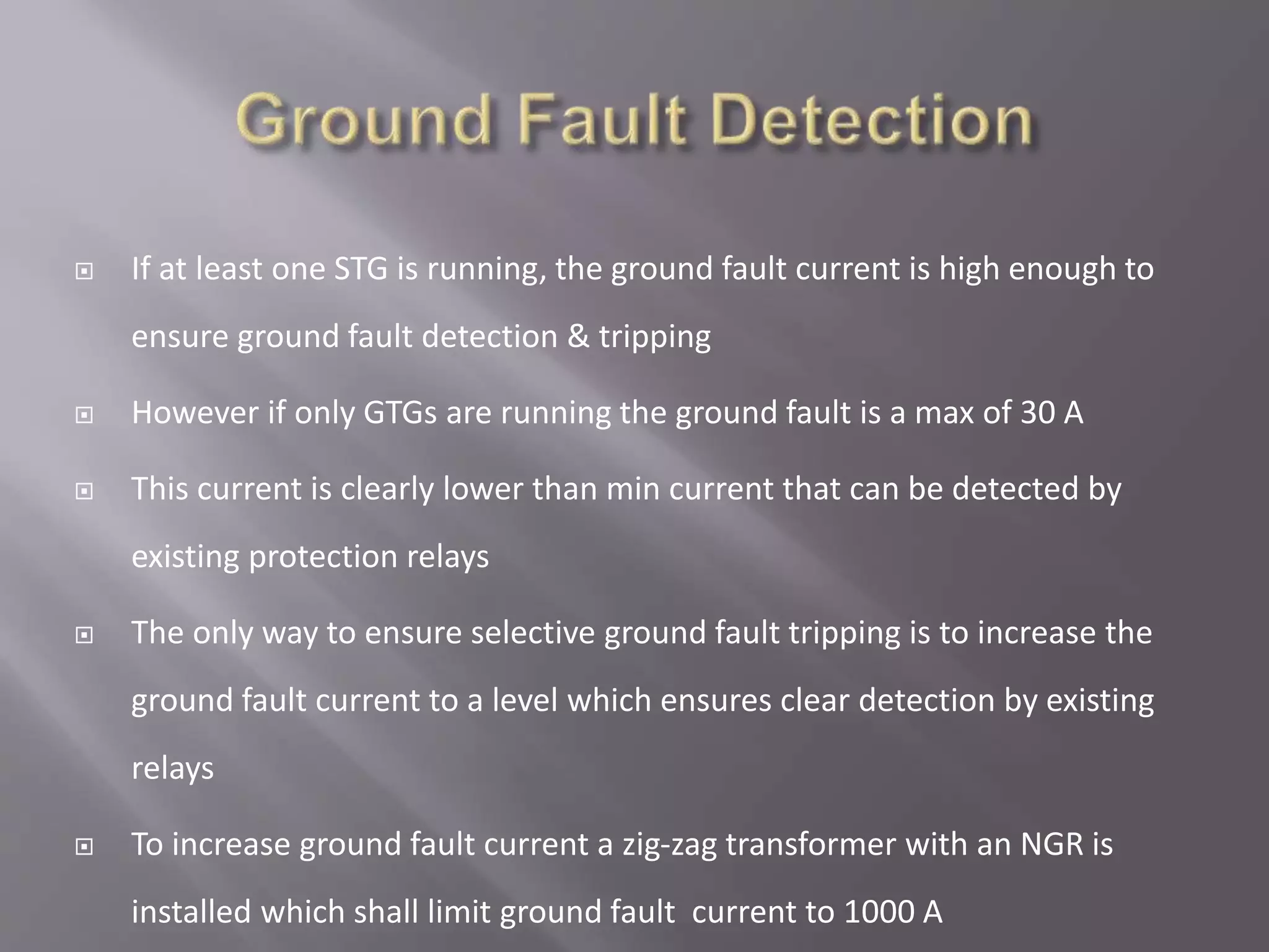
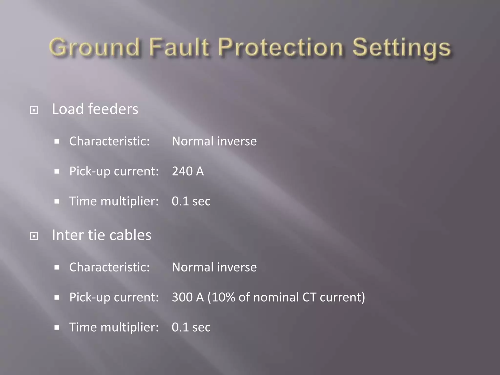
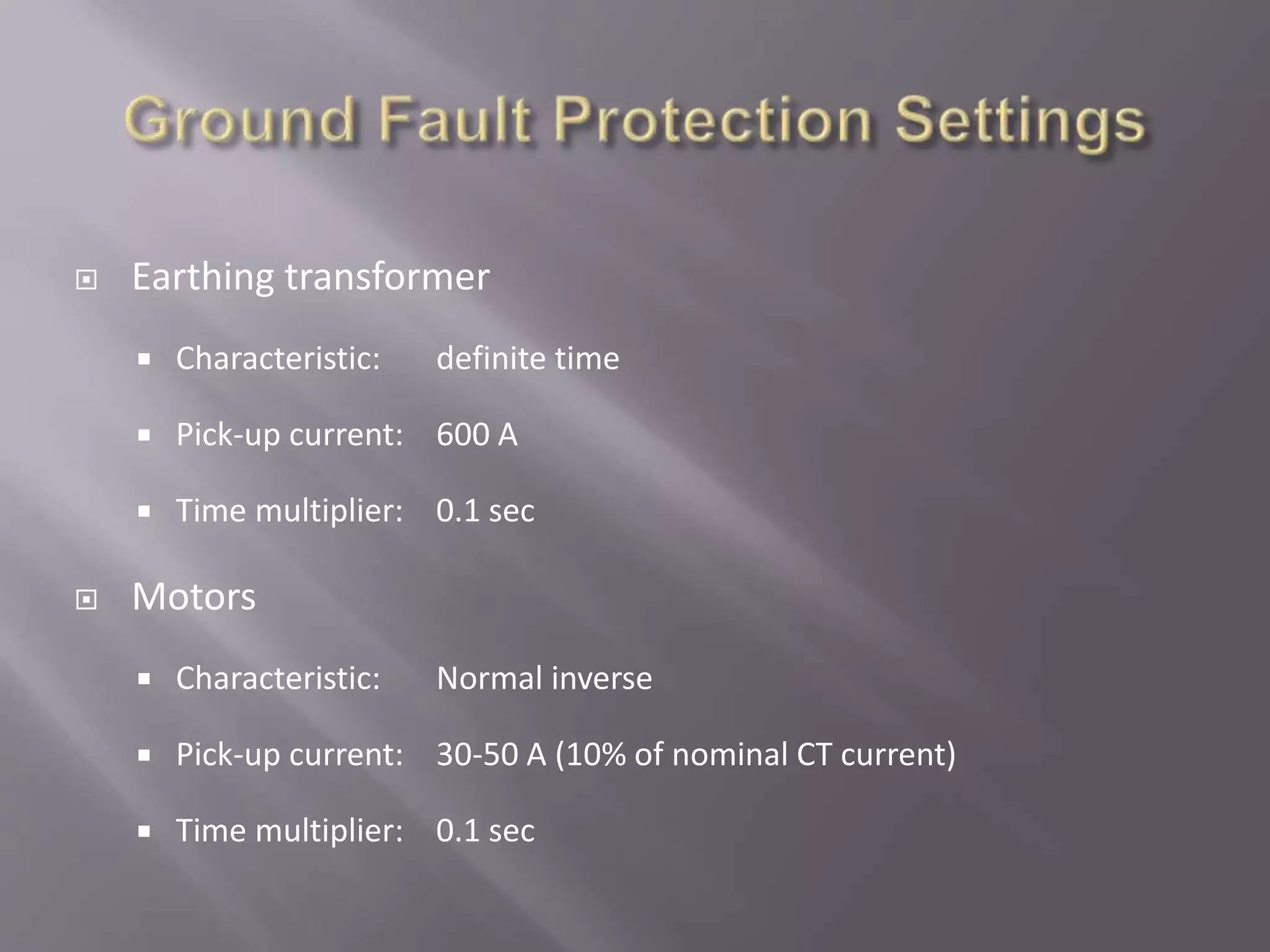
 What is NGR ?
 Why use an NGR ?
 What is a Zig – Zag Transformer ?
 How a Zig – Zag Transformer works
 Neutral Grounding Devices Data
 NGR System before Co-Gen
 NGR System after Co-Gen
 Ground Fault Detection
 NGR Operational Schemes
 Ground Fault Protection Settings
 NGR stands for Neutral Grounding Resistor (also called Neutral Earthing
Resistor )
 NGR limits the current that would flow through the neutral point of a
transformer or generator in the event of an earth fault.
 NGR limits fault currents to a value that does not cause any further
damage to switchgear, generators or transformers beyond what has
already been caused by the fault itself.
 There are various types of system grounding, including:
 Solid grounding
 High resistance grounding
 Low resistance grounding
 An Electrical Power System is usually a 3 phase
balanced system
 Under normal load the treatment of neutral does
not effect behavior of network
 However in case of a line to ground fault the
behavior of network depends decisively on the
neutral grounding method used
 Also known as earthing transformer
 A Zigzag transformer is a special purpose
transformer with a zigzag winding arrangement
 It has primary windings but no secondary winding
 Application
 To derive an earth reference point for an ungrounded
electrical system To control harmonic currents
 As with other three-phase
transformers, the zigzag transformer
contains six coils on three cores. The
first coil on each core is connected
contrariwise to the second coil on the
next core. The second coils are then
all tied together to form the neutral
and the phases are connected to the
primary coils. Each phase, therefore,
couples with each other phase and
the voltages cancel out. As such, there
would be negligible current through
the neutral pole and it can be tied to
ground.
 If one phase, or more, faults to earth, the
voltage applied to each phase of the
transformer is no longer in balance; fluxes
in the windings no longer oppose. Zero
sequence (earth fault) current exists
between the transformer’s neutral to the
faulting phase. Hence, the purpose of a
zigzag transformer is to provide a return
path for earth faults on delta-connected
systems. With negligible current in the
neutral under normal conditions, engineers
typically elect to under size the
transformer; a short time rating is applied
(i.e., the transformer can only carry full
rated current for, say, 60 s).
 NGR
 Nominal voltage = 6 / √3 kV
 Short time current = 1000 A
 Resistance = 3.1 Ω
 Operation time = 10 Sec
 Earthing Transformer
 Vector group ZN
 Nominal voltage = 6kV
 Short time current = 1000 A
 Short time power = 3.46 MVA
 Operation time = 10 Sec
 The neutrals of all STGs were connected to one common neutral
resistor
 The old NGR has a resistance of 3.2 Ω to limit the earth fault
current to 1000 A
 The protection relays and their respective CTs are chosen
accordingly (800/1, 1200/1)
 Relays are set to 20% i.e. 160A & 240A
 At least two times of this current is required to ensure tripping
time of less than 1 sec
 Three new GTGs of 14 MVA each
 The neutrals of the three generators are connected to three
individual neutral resistors
 Each NGR has a resistance of 340 Ω and in case of fault feeds a
neutral current of 10 A
 An EDG of 2.25 MVA is also installed with an NGR of 9 Ω and feeds
a current of 250 A
 No more than three out of six STGs or GTGs can be operated at a
time to limit the max S.C current to the rated value of SWGR
 If at least one STG is running, the ground fault current is high enough to
ensure ground fault detection & tripping
 However if only GTGs are running the ground fault is a max of 30 A
 This current is clearly lower than min current that can be detected by
existing protection relays
 The only way to ensure selective ground fault tripping is to increase the
ground fault current to a level which ensures clear detection by existing
relays
 To increase ground fault current a zig-zag transformer with an NGR is
installed which shall limit ground fault current to 1000 A
 Load feeders
 Characteristic: Normal inverse
 Pick-up current: 240 A
 Time multiplier: 0.1 sec
 Inter tie cables
 Characteristic: Normal inverse
 Pick-up current: 300 A (10% of nominal CT current)
 Time multiplier: 0.1 sec
 Earthing transformer
 Characteristic: definite time
 Pick-up current: 600 A
 Time multiplier: 0.1 sec
 Motors
 Characteristic: Normal inverse
 Pick-up current: 30-50 A (10% of nominal CT current)
 Time multiplier: 0.1 sec
NGR & Zig-Zag Transformer.pptx

NGR & Zig-Zag Transformer.pptx

  • 2.
     What isNGR ?  Why use an NGR ?  What is a Zig – Zag Transformer ?  How a Zig – Zag Transformer works  Neutral Grounding Devices Data  NGR System before Co-Gen  NGR System after Co-Gen  Ground Fault Detection  NGR Operational Schemes  Ground Fault Protection Settings
  • 3.
     NGR standsfor Neutral Grounding Resistor (also called Neutral Earthing Resistor )  NGR limits the current that would flow through the neutral point of a transformer or generator in the event of an earth fault.  NGR limits fault currents to a value that does not cause any further damage to switchgear, generators or transformers beyond what has already been caused by the fault itself.  There are various types of system grounding, including:  Solid grounding  High resistance grounding  Low resistance grounding
  • 4.
     An ElectricalPower System is usually a 3 phase balanced system  Under normal load the treatment of neutral does not effect behavior of network  However in case of a line to ground fault the behavior of network depends decisively on the neutral grounding method used
  • 6.
     Also knownas earthing transformer  A Zigzag transformer is a special purpose transformer with a zigzag winding arrangement  It has primary windings but no secondary winding  Application  To derive an earth reference point for an ungrounded electrical system To control harmonic currents
  • 9.
     As withother three-phase transformers, the zigzag transformer contains six coils on three cores. The first coil on each core is connected contrariwise to the second coil on the next core. The second coils are then all tied together to form the neutral and the phases are connected to the primary coils. Each phase, therefore, couples with each other phase and the voltages cancel out. As such, there would be negligible current through the neutral pole and it can be tied to ground.
  • 10.
     If onephase, or more, faults to earth, the voltage applied to each phase of the transformer is no longer in balance; fluxes in the windings no longer oppose. Zero sequence (earth fault) current exists between the transformer’s neutral to the faulting phase. Hence, the purpose of a zigzag transformer is to provide a return path for earth faults on delta-connected systems. With negligible current in the neutral under normal conditions, engineers typically elect to under size the transformer; a short time rating is applied (i.e., the transformer can only carry full rated current for, say, 60 s).
  • 11.
     NGR  Nominalvoltage = 6 / √3 kV  Short time current = 1000 A  Resistance = 3.1 Ω  Operation time = 10 Sec  Earthing Transformer  Vector group ZN  Nominal voltage = 6kV  Short time current = 1000 A  Short time power = 3.46 MVA  Operation time = 10 Sec
  • 12.
     The neutralsof all STGs were connected to one common neutral resistor  The old NGR has a resistance of 3.2 Ω to limit the earth fault current to 1000 A  The protection relays and their respective CTs are chosen accordingly (800/1, 1200/1)  Relays are set to 20% i.e. 160A & 240A  At least two times of this current is required to ensure tripping time of less than 1 sec
  • 14.
     Three newGTGs of 14 MVA each  The neutrals of the three generators are connected to three individual neutral resistors  Each NGR has a resistance of 340 Ω and in case of fault feeds a neutral current of 10 A  An EDG of 2.25 MVA is also installed with an NGR of 9 Ω and feeds a current of 250 A  No more than three out of six STGs or GTGs can be operated at a time to limit the max S.C current to the rated value of SWGR
  • 16.
     If atleast one STG is running, the ground fault current is high enough to ensure ground fault detection & tripping  However if only GTGs are running the ground fault is a max of 30 A  This current is clearly lower than min current that can be detected by existing protection relays  The only way to ensure selective ground fault tripping is to increase the ground fault current to a level which ensures clear detection by existing relays  To increase ground fault current a zig-zag transformer with an NGR is installed which shall limit ground fault current to 1000 A
  • 20.
     Load feeders Characteristic: Normal inverse  Pick-up current: 240 A  Time multiplier: 0.1 sec  Inter tie cables  Characteristic: Normal inverse  Pick-up current: 300 A (10% of nominal CT current)  Time multiplier: 0.1 sec
  • 21.
     Earthing transformer Characteristic: definite time  Pick-up current: 600 A  Time multiplier: 0.1 sec  Motors  Characteristic: Normal inverse  Pick-up current: 30-50 A (10% of nominal CT current)  Time multiplier: 0.1 sec