Download as PDF, PPTX
![Pros and cons of multi-terminal HVDC systems
+
[1] Less active losses than the AC solution for the same
voltage level; no need for reactive power compensation in
submarine cable lines.
[2] Act as a firewall between different AC areas; (partial)
decoupling of the dynamics between the zones.
[3] Control over the power transferred in the HVDC lines (eases
the operation of the power system - may foster merchant
investment).
-
[1] Hardware technology not yet fully mature (e.g., problems
with HVDC breakers)
[2] Still not yet understood how a multi-terminal HVDC should
be operated, especially in real-time.
2](https://image.slidesharecdn.com/ernst-tainan-2012-150328095748-conversion-gate01/75/Multi-terminal-HVDC-systems-and-ancillary-services-3-2048.jpg)
![Two major shortcomings of this scheme
[1] In case of a dysfunction in the multi-terminal HVDC system,
load imbalances will be created in the areas and the areas will
lose the possibility to rely on primary reserves from other
areas.
[2] If time for communicating the frequency information (τ on
the figure) between the areas is too large, instabilities may
occur !
14](https://image.slidesharecdn.com/ernst-tainan-2012-150328095748-conversion-gate01/75/Multi-terminal-HVDC-systems-and-ancillary-services-15-2048.jpg)
![Theoretical results
The analysis is much more technical than for the
power-injection-based control scheme !
A “rough summary” of some of the results obtained:
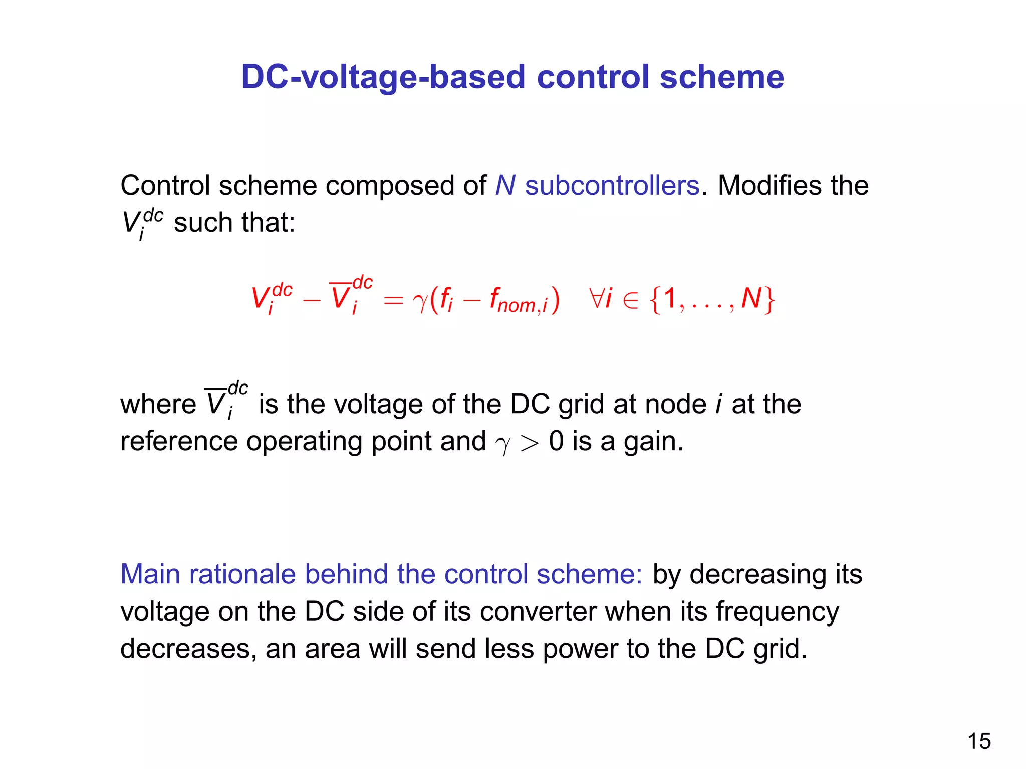
[1] If γ is small enough, then a load increase in area i leads to
a new equilibrium point where the differences between the
frequencies deviations are smaller. This shows that the control
scheme leads to a sharing of the primary frequency reserve.
[2] If γ is small enough, then this new equilibrium is
asymptotically stable.
Note: The detailed analysis can be found in : ”Cooperative control of a multi-terminal high-voltage DC
network”. J. Dai, Y. Phulpin, A. Sarlette and D. Ernst. Submitted.
16](https://image.slidesharecdn.com/ernst-tainan-2012-150328095748-conversion-gate01/75/Multi-terminal-HVDC-systems-and-ancillary-services-17-2048.jpg)
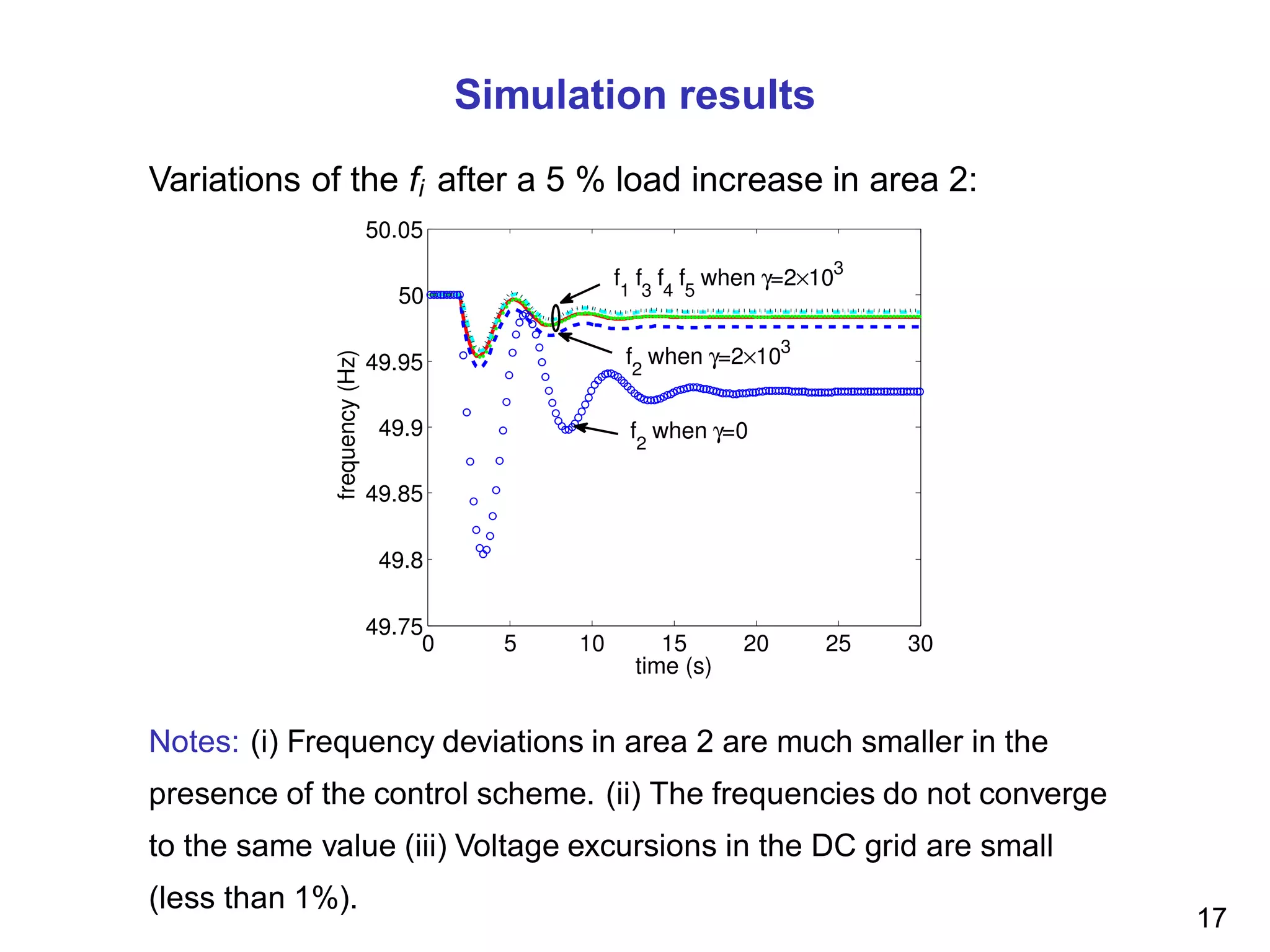

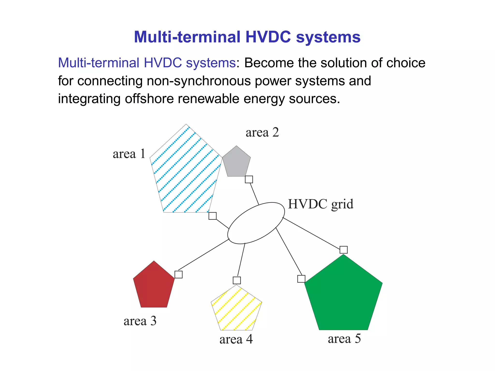
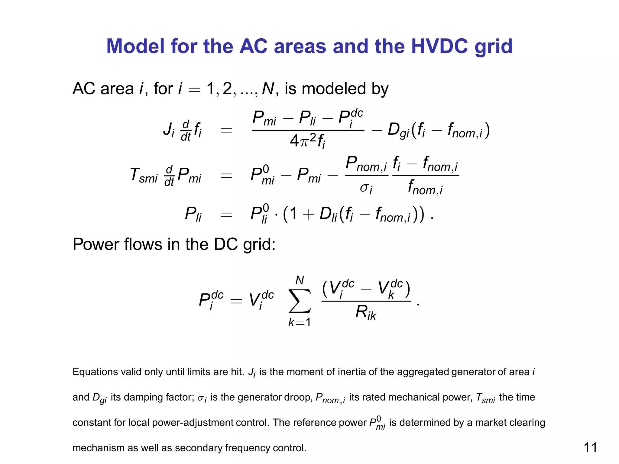
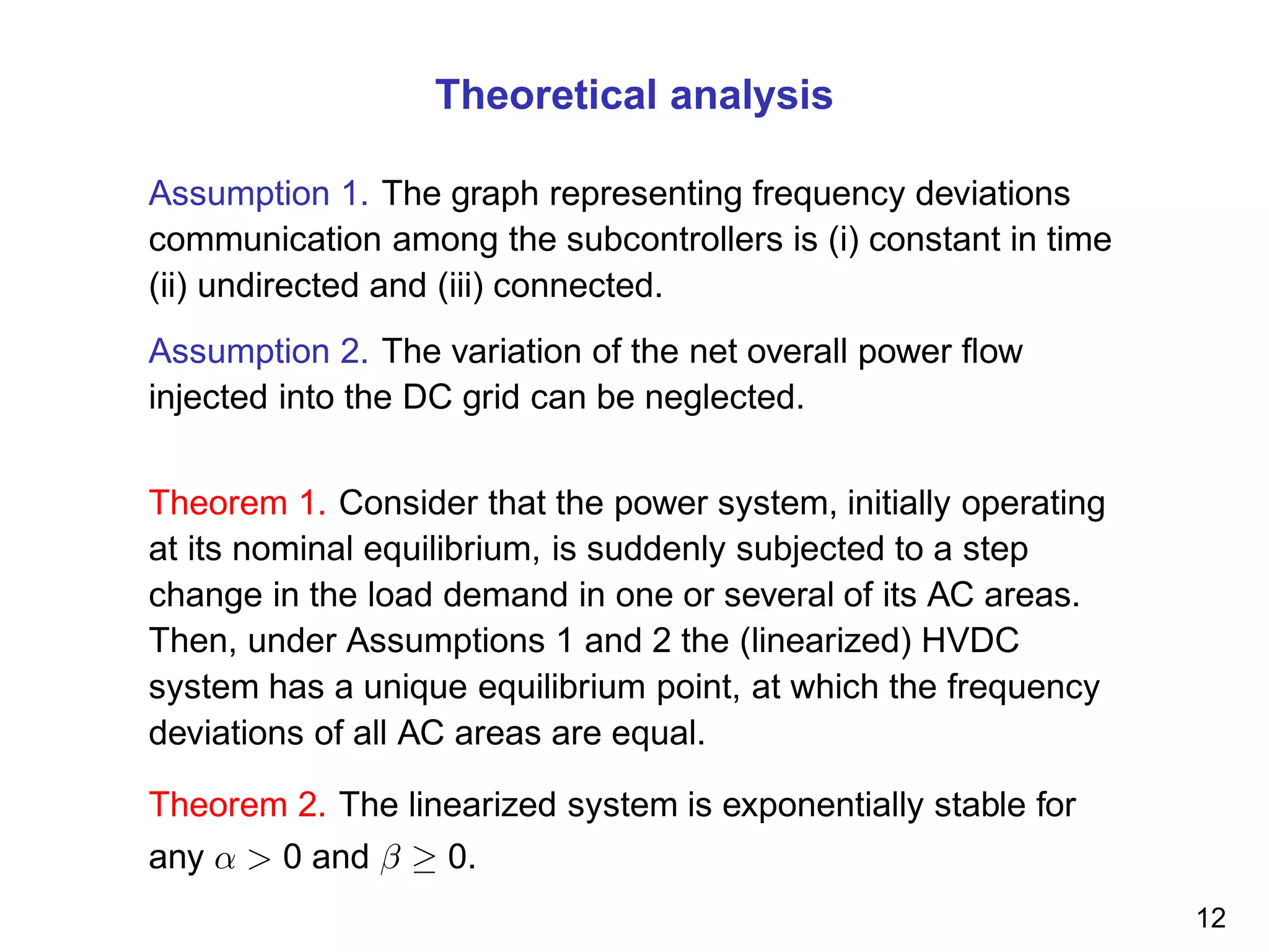
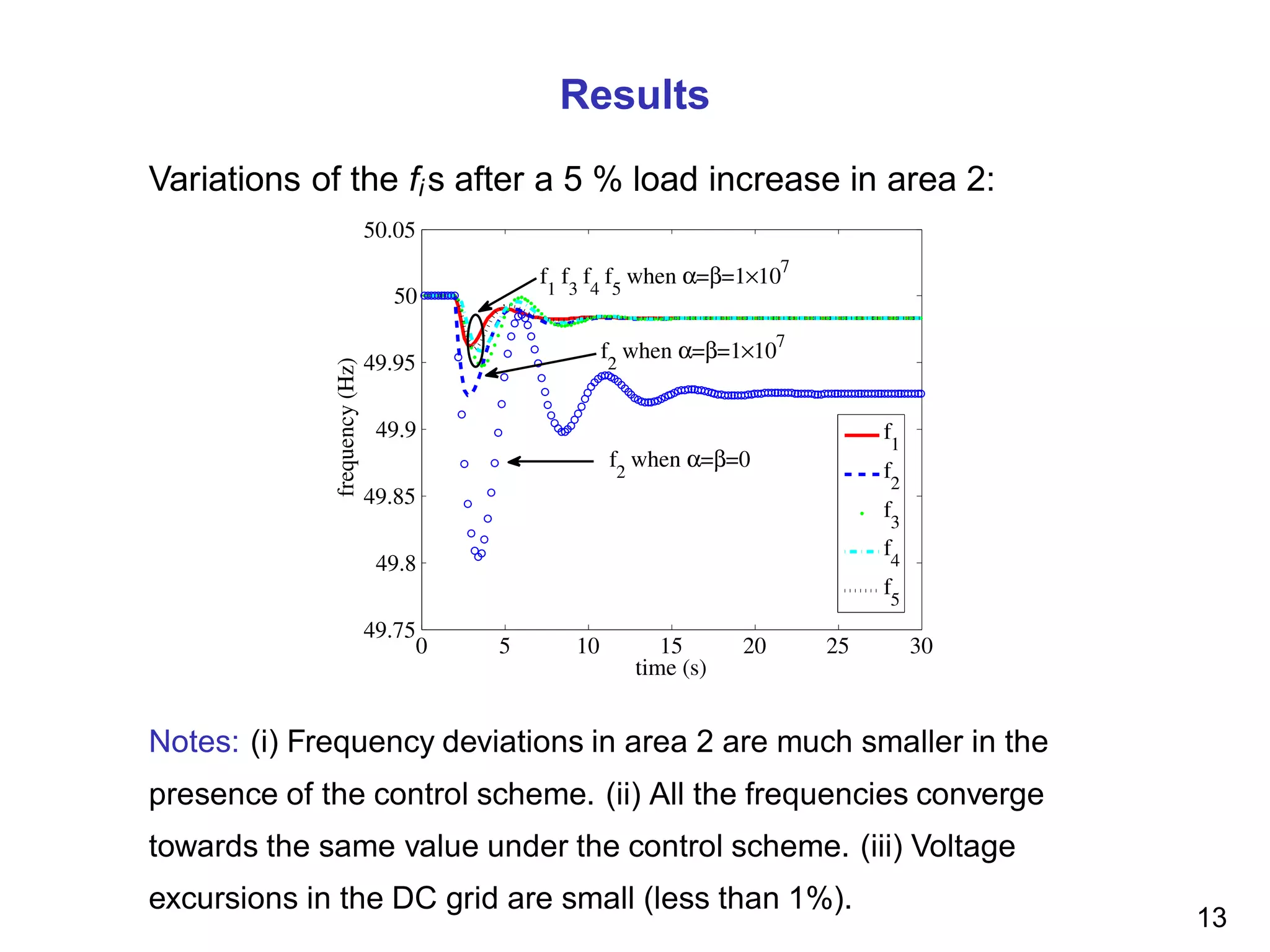
1) Multi-terminal HVDC systems can connect non-synchronous power systems and integrate offshore renewable energy sources more efficiently than AC solutions. 2) The document discusses control schemes for multi-terminal HVDC systems to allow them to provide ancillary services like frequency control to connected AC areas. 3) Two control schemes are analyzed - one that modulates active power injections and one that modulates DC voltages - and theoretical analysis and simulations show they can help stabilize frequency deviations between areas after disturbances.