This document summarizes a research paper on load frequency control (LFC) for multi-area power systems with communication delays. It presents state space models of LFC that include time-varying delays in both the feed-forward and feedback communication channels. It then proposes a delay-dependent controller and evaluates its effectiveness compared to a conventional PI controller using a two-area LFC model with simulated time-varying delays. The results show the proposed controller can robustly stabilize the power system even with delays, while the PI controller's performance degrades.
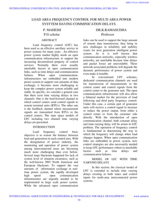
![For LFC studies, all the generators in each
area are represented equivalently by one
single machine. In the following models in
this paper, we omit the time ݐ in every
variable for convenience, such as (ݐ) is
written as ݔ.
For area i, the dynamics of LFC are described
by
)(
111
11
111
P jPiT ijPij
tie
Pci
T gi
Pvi
T gi
f i
T giRi
Pvi
Pvi
T chi
Pmi
T chi
Pmi
PLi
M i
Pij
tie
M i
Pmi
M i
f i
M i
Dif i
∆−∆=
∆+∆−∆
−
=•∆
∆+∆
−
=∆ •
∆−∆−∆+∆
−
=∆ •
where
f i∆ frequency deviation
pmi∆ generator mechanical power deviation
Pvi∆ turbine valve position deviation
Pci∆ load reference set-point
Pij
tie∆ tie-line power flow between area i and j
PLi∆ load deviation
Mi moment of inertia of generator i;
Di damping coefficient of generator i;
T gi time constant of governor i
Tchi time constant of turbine i
Tij stiffness constant
Ri speed droop coefficient
PLiFix j
N
ijj
AijuiBixiAixi ∆+∑
≠=
++=•
,1
.
∑
≠=
−
−−
−
−−
=
000
,1
0
1
0
1
0
11
0
1
0
1
N
ijj
Tij
T giT giRi
TchiTchi
MiMiMi
Di
Ai
=
000
0000
0000
0000
Tij
Aij
= 0
1
00
T gi
Bi
−
= 000
1
Mi
Fi
The ACE signal in a multi-area LFC
scheme is defined as follows:
Ptieif iBiACEi ∆+∆= .
For the whole multi-area power system, an
linear time invariant(LTI) interconnected
model is given by
PLFBuAxx ∆++=
•
Moreover, we consider two time varying
bounded delays ݀1(ݐ), ݀2(ݐ) existing in states
x and control input u. The two delays satisfy
the following conditions:
0 ≤ ݀1(ݐ) ≤ ݀ˆ1, 0 ≤ ݀2(ݐ) ≤ ݀ˆ2; ݀1˙(ݐ) ≤ ߩ1
≤ 1, ݀2˙(ݐ) ≤ ߩ2 ≤ 1.
The LFC model with states and
control inputs delays is given by
PLFtdtuBdButdtxAdAxx ∆+−++−+=
•
))(2(_))(1(
where
{ }T
AdnAdAddiagAd 21=
{ }T
BdnBdBddiagBd 21=
−−
=
0000
0000
0000
1
00
MiMi
Di
Adi
= 0
1
00
T gi
Bdi
[ ]Pij
tiePviPmif ixi ∆∆∆∆=
INTERNATIONAL CONFERENCE ON CIVIL AND MECHANICAL ENGINEERING, ICCME-2014
INTERNATIONAL ASSOCIATION OF ENGINEERING & TECHNOLOGY FOR SKILL DEVELOPMENT www.iaetsd.in
35
ISBN:378-26-138420-0241](https://image.slidesharecdn.com/iaetsd-loadareafrequencycontrolformultiareapower-150420110722-conversion-gate02/85/Iaetsd-load-area-frequency-control-for-multi-area-power-2-320.jpg)
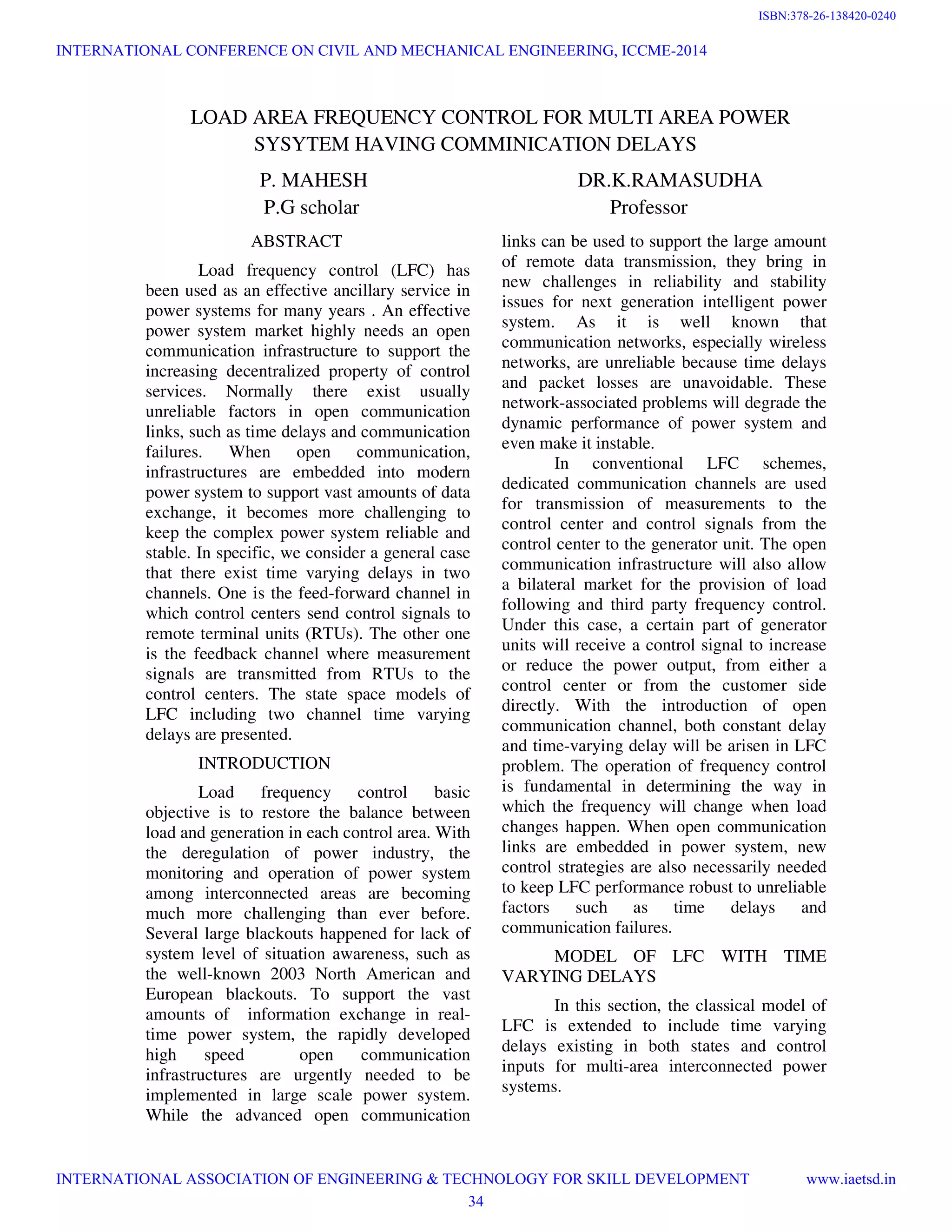
![Fig(2) for area2
Fig(3) for area 1
CONCLUSION
This paper considers the modeling and delay
dependent stabilization problems of LFC for
power system with both feed
feedback time varying communication delays.
The state space models of LFC are presented,
including the two-channel time varying
delays. In case studies, two-area LFC model
is built to
evaluate the effectiveness of the proposed
method. With the comparison to the
conventional PI controller, it is shown that the
proposed controller can keep the power
system robustly stable and good convergence
rate when there exist time varying delays i
two channels.
REFERENCES
[1] Shichao liu,Xiaping P.Liu,”Load
frequency control for wide area monitoring
and control system in power system with
communication links”,IEEE transaction
2012.
[2]G.Anderson,P.Donalek et.al,”Causes of the
2003 major grid blockouts in North America
and Europe,and recommended means to
improve system dynamic performance”,IEEE
Transcationspowersystems,vol.20,n0.4,pp.19
22-1928,2005
[3] D. Karlsson, M. Hemmingsson and S.
Lindahl, “Wide area system
and control: terminology, phenomena, and
solution implementationstrategies ,”
Power and Energy Magazine, vol. 2, no. 5,
pp. 68-76, 2004.
[4] J. Machovski, J. W. Blalek, and J. R.
Bumby, “Power system dynamics
stability,” John Wiley & Sons, 1998.
[5] S. Bhovmik, K. Tomsovic, and A.
Bose, “Communication models
party load frequency control,”
Transactions on PowerSystems
no. 1, pp. 543-548, 2004
[6] L. Jiang, W. Yao, Q. H. Wu et. al,
“Delay-dependent stability for load
CONCLUSION
This paper considers the modeling and delay
stabilization problems of LFC for
power system with both feed-forward and
feedback time varying communication delays.
The state space models of LFC are presented,
channel time varying
area LFC model
evaluate the effectiveness of the proposed
method. With the comparison to the
conventional PI controller, it is shown that the
proposed controller can keep the power
system robustly stable and good convergence
rate when there exist time varying delays in
REFERENCES
[1] Shichao liu,Xiaping P.Liu,”Load
frequency control for wide area monitoring
and control system in power system with
communication links”,IEEE transaction
[2]G.Anderson,P.Donalek et.al,”Causes of the
lockouts in North America
and Europe,and recommended means to
improve system dynamic performance”,IEEE
Transcationspowersystems,vol.20,n0.4,pp.19
D. Karlsson, M. Hemmingsson and S.
Lindahl, “Wide area system monitoring
ogy, phenomena, and
solution implementationstrategies ,” IEEE
, vol. 2, no. 5,
] J. Machovski, J. W. Blalek, and J. R.
Bumby, “Power system dynamics and
stability,” John Wiley & Sons, 1998.
Tomsovic, and A.
Bose, “Communication models for third
party load frequency control,” IEEE
Transactions on PowerSystems, vol. 19,
Jiang, W. Yao, Q. H. Wu et. al,
dependent stability for load
INTERNATIONAL CONFERENCE ON CIVIL AND MECHANICAL ENGINEERING, ICCME-2014
INTERNATIONAL ASSOCIATION OF ENGINEERING & TECHNOLOGY FOR SKILL DEVELOPMENT www.iaetsd.in
37
ISBN:378-26-138420-0243](https://image.slidesharecdn.com/iaetsd-loadareafrequencycontrolformultiareapower-150420110722-conversion-gate02/85/Iaetsd-load-area-frequency-control-for-multi-area-power-4-320.jpg)
![frequency control with constant and time-
varying delays,” in Power and Energy
Society General Meeting, 2009. PES ’09.
IEEE , Calgary, AB, Canada, 2009
[7] S. Xu, J. Lam, and Y. Zou,“improved
conditions for delay-dependant robust
stability and stabilization of uncertain
discrete time delay systems,”Asian J.
Control, vol. 7, no. 3, pp. 344-348, 2005
[8] L. E. Ghaoui, F. Oustry, and M.
Aitrami, “A cone complementary
linearization algorithm for static output-
feedback and related problems,” IEEE
Transactions on Autom. Control, vol. 19,
no. 3, pp. 1508-1515, 2004.
[9] V.C. Gungor, and F.C. Lambert, “A
survey on communication networks
for electric system automation,” Computer
Networks, vol. 50, no. 7, pp.
877-897, 2006
[10] P. Kundar, Power system stability and
control, Stateplace, New York:
McGraw-Hill, 1994.
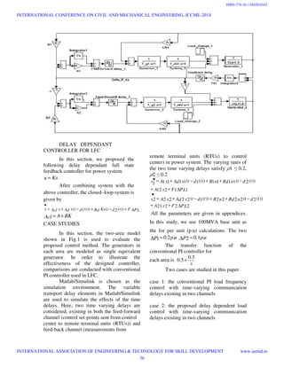
APPENDIX A
Two–area power system parameters are
shown as follows
Area 1:
5.411
1
1
1
,121
,5.11,05.01,4.01,17.01
=+=
=
====
D
R
B
M
DRsT gsTch
Area 2:
8.612
2
1
2
,122
,8.12,05.02,35.02,2.02
=+=
=
====
D
R
B
M
DRsT gsTch
APPENDIX B
Area 2
[ ]
[ ]
[ ]T
F
T
Bd
Ad
T
B
A
A
0000833.02
088571.2002
0000
0000
0000
0833.00015.0
2
08571.2002
0005.0
0000
0000
0000
21
0005.0
08571.201429.57
0550
0833.000833.015.0
1
−=
=
−−
=
=
=
−−
−
−−
=
[ ]
[ ]
[ ]T
F
T
Bd
T
B
Ad
A
A
AREA
000833.01
05.2001
05.2001
0000
0000
0000
0833.000125.0
1
0005.0
0000
0000
0000
12
0005.0
05.2050
08824.58824.50
0833.000833.0125.0
1
1
−=
=
=
−−
=
=
−−
−
−−
=
INTERNATIONAL CONFERENCE ON CIVIL AND MECHANICAL ENGINEERING, ICCME-2014
INTERNATIONAL ASSOCIATION OF ENGINEERING & TECHNOLOGY FOR SKILL DEVELOPMENT www.iaetsd.in
38
ISBN:378-26-138420-0244](https://image.slidesharecdn.com/iaetsd-loadareafrequencycontrolformultiareapower-150420110722-conversion-gate02/85/Iaetsd-load-area-frequency-control-for-multi-area-power-5-320.jpg)


![[9] a systematic parameter tuning of pi current controller for lcl type activ...](https://cdn.slidesharecdn.com/ss_thumbnails/9asystematicparametertuningofpicurrentcontrollerforlcl-typeactiverectifiersunderunbalancedgridvoltag-200723180821-thumbnail.jpg?width=640&height=640&fit=bounds)


![[Deck] What's New in Spark-Iceberg Integration via DSV2.pptx](https://cdn.slidesharecdn.com/ss_thumbnails/deckwhatsnewinspark-icebergintegrationviadsv2-260210005337-25955b12-thumbnail.jpg?width=640&height=640&fit=bounds)


