Downloaded 32 times
![CSULB MAY 22, 2006 8
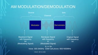
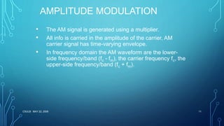
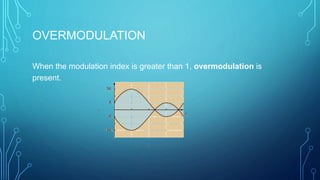
AMPLITUDE MODULATION
• The amplitude of high-carrier signal is varied
according to the instantaneous amplitude of the
modulating message signal m(t).
Carrier Signal: or
Modulating Message Signal: or
The AM Signal:
cos(2 ) cos( )
( ): cos(2 ) cos( )
( ) [ ( )]cos(2 )
c c
m m
AM c c
f t t
m t f t t
s t A m t f t
](https://image.slidesharecdn.com/pocppt1-170611140623/85/multiplexing-and-amplitude-modulation-8-320.jpg)

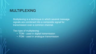
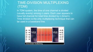
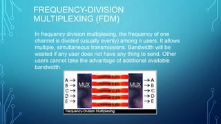
1) Multiplexing is a technique that combines multiple message signals into a composite signal for transmission over a common channel. The two main types are time-division multiplexing (TDM) used in digital transmission, and frequency-division multiplexing (FDM) used in analogue transmission. 2) In TDM, the time of one channel is divided among multiple users so each appears to have the full channel for a fraction of the total time. In FDM, the frequency of one channel is divided among users so multiple transmissions can occur simultaneously. 3) Modulation involves changing a characteristic of a high-frequency carrier signal based on the instantaneous amplitude of an information signal. This allows multiple signals to be


![[Deck] What's New in Spark-Iceberg Integration via DSV2.pptx](https://cdn.slidesharecdn.com/ss_thumbnails/deckwhatsnewinspark-icebergintegrationviadsv2-260210005337-25955b12-thumbnail.jpg?width=640&height=640&fit=bounds)


