The document discusses the physical layer design of WCDMA networks. It provides an overview of WCDMA network architecture and the UMTS network model. It then describes the physical channels, transport formats, channel coding, spreading techniques and code types used in the WCDMA uplink and downlink. Key aspects covered include dedicated and common physical channels, orthogonal variable spreading factor channelization codes, scrambling codes, and transport block sets.
WCDMA Physical LayerDesign A. Chockalingam Assistant Professor Indian Institute of Science, Bangalore-12 [email_address] http://ece.iisc.ernet.in/~achockal
2.
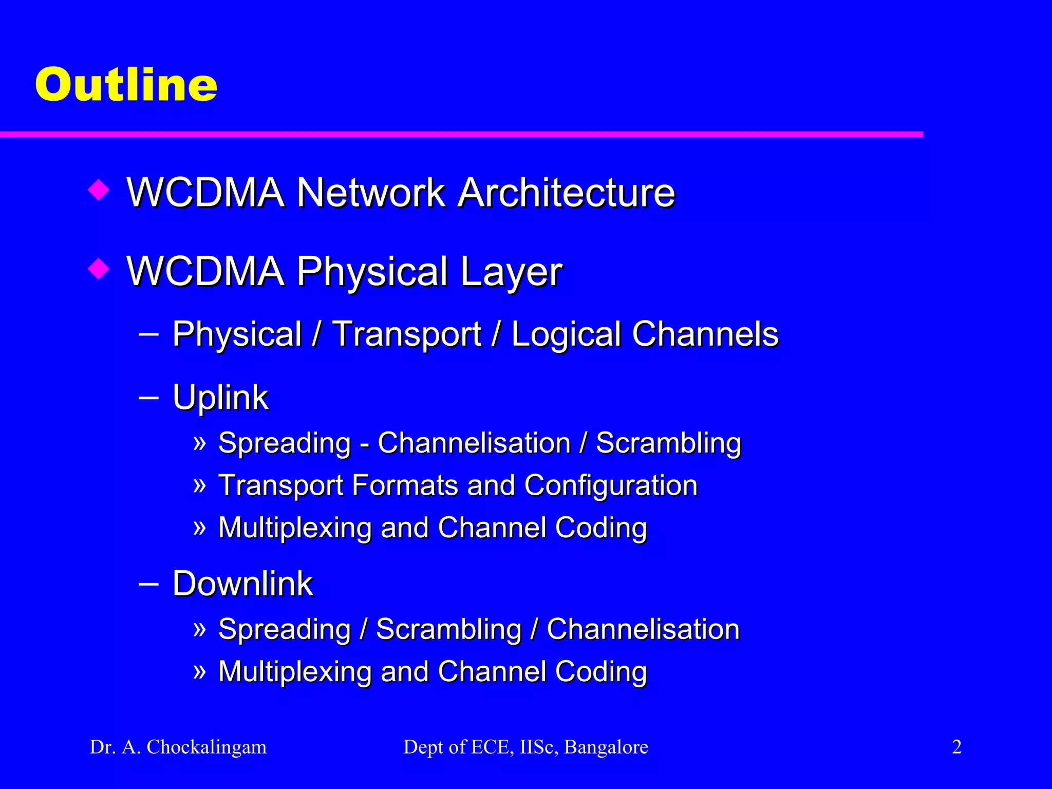
Dr. A. Chockalingam Dept of ECE, IISc, Bangalore Outline WCDMA Network Architecture WCDMA Physical Layer Physical / Transport / Logical Channels Uplink Spreading - Channelisation / Scrambling Transport Formats and Configuration Multiplexing and Channel Coding Downlink Spreading / Scrambling / Channelisation Multiplexing and Channel Coding
3.
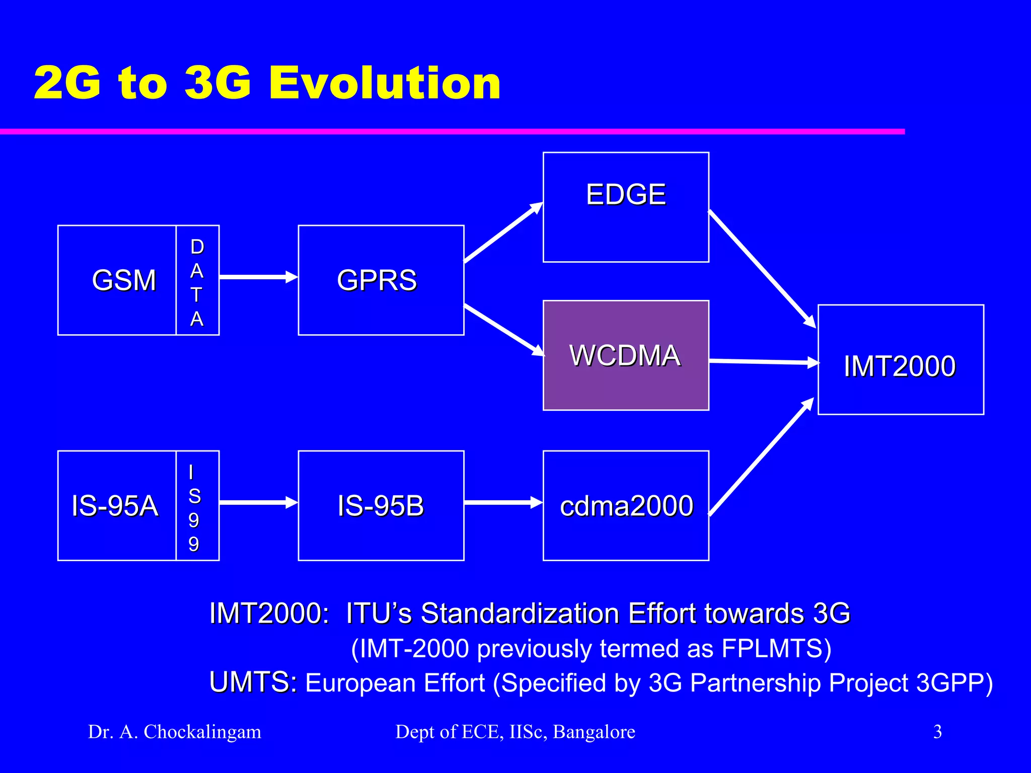
Dr. A. Chockalingam Dept of ECE, IISc, Bangalore 2G to 3G Evolution IS-95A IS-95B cdma2000 IMT2000 IMT2000: ITU’s Standardization Effort towards 3G (IMT-2000 previously termed as FPLMTS) UMTS: European Effort (Specified by 3G Partnership Project 3GPP) GSM GPRS WCDMA EDGE D A T A I S 9 9
4.
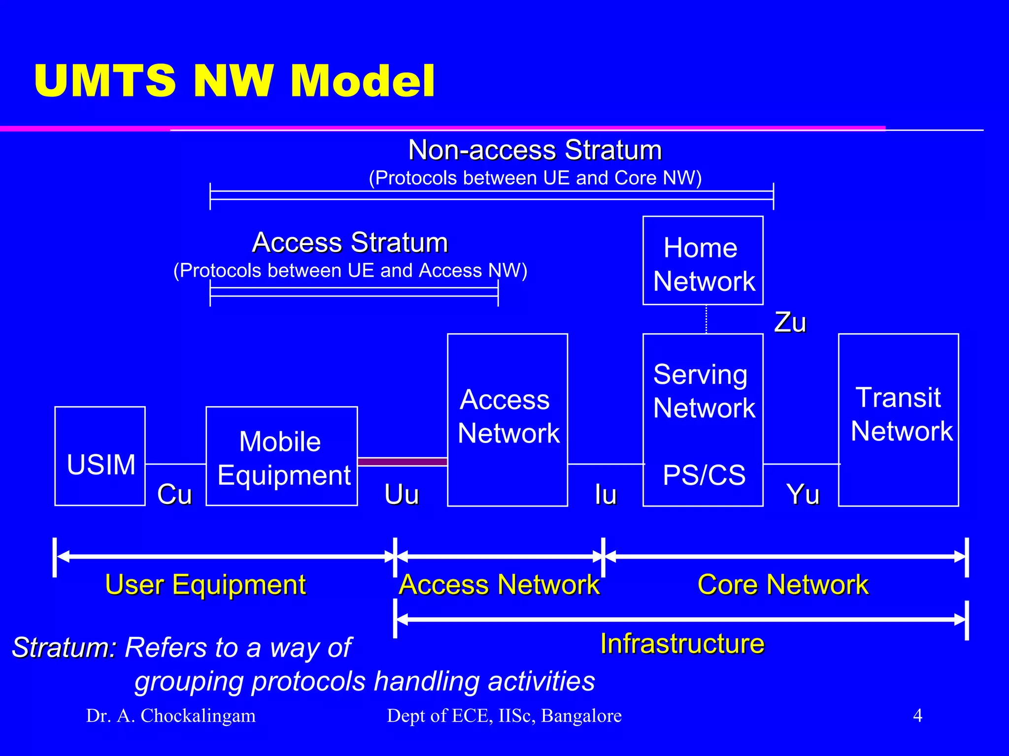
Dr. A. Chockalingam Dept of ECE, IISc, Bangalore UMTS NW Model USIM Mobile Equipment Access Network Serving Network PS/CS Transit Network Cu Uu Iu Yu User Equipment Access Network Core Network Infrastructure Home Network Access Stratum (Protocols between UE and Access NW) Non-access Stratum (Protocols between UE and Core NW) Zu Stratum: Refers to a way of grouping protocols handling activities
5.
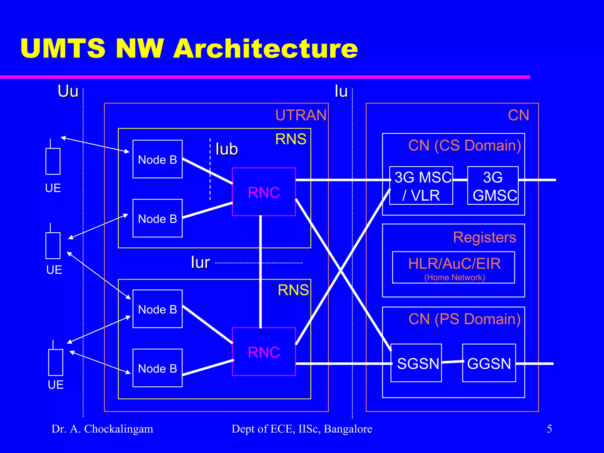
Dr. A. Chockalingam Dept of ECE, IISc, Bangalore UMTS NW Architecture Node B UE UE UE Node B Node B Node B RNC RNC UTRAN RNS RNS CN CN (CS Domain) CN (PS Domain) SGSN GGSN Registers HLR/AuC/EIR (Home Network) 3G MSC / VLR 3G GMSC Uu Iu Iur Iub
6.
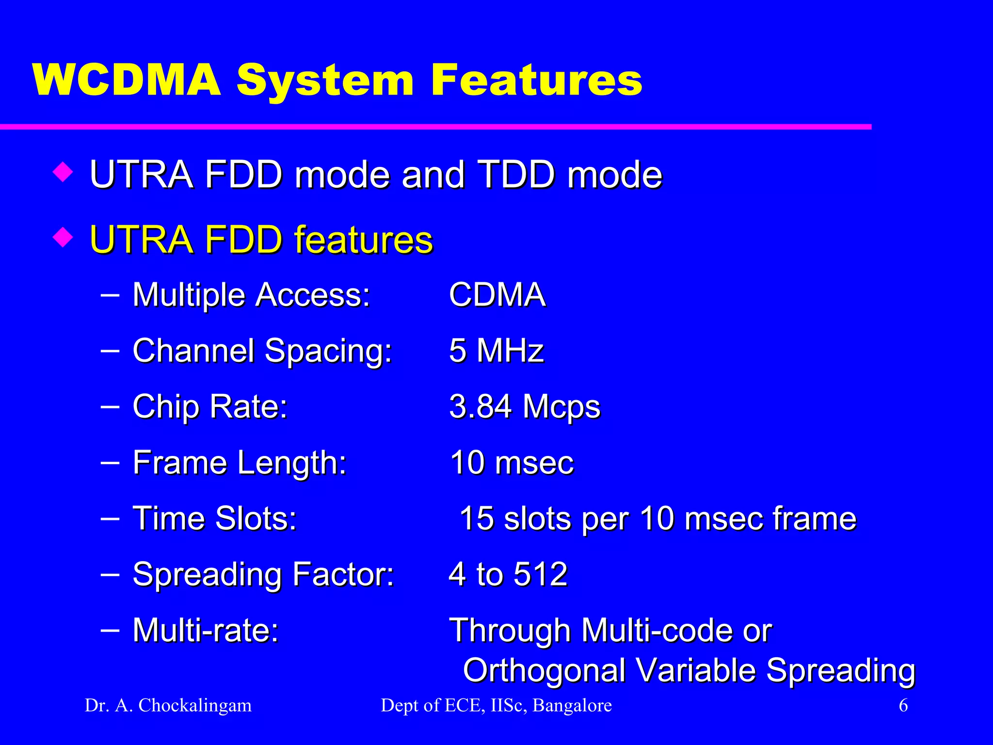
Dr. A. Chockalingam Dept of ECE, IISc, Bangalore WCDMA System Features UTRA FDD mode and TDD mode UTRA FDD features Multiple Access: CDMA Channel Spacing: 5 MHz Chip Rate: 3.84 Mcps Frame Length: 10 msec Time Slots: 15 slots per 10 msec frame Spreading Factor: 4 to 512 Multi-rate: Through Multi-code or Orthogonal Variable Spreading
7.
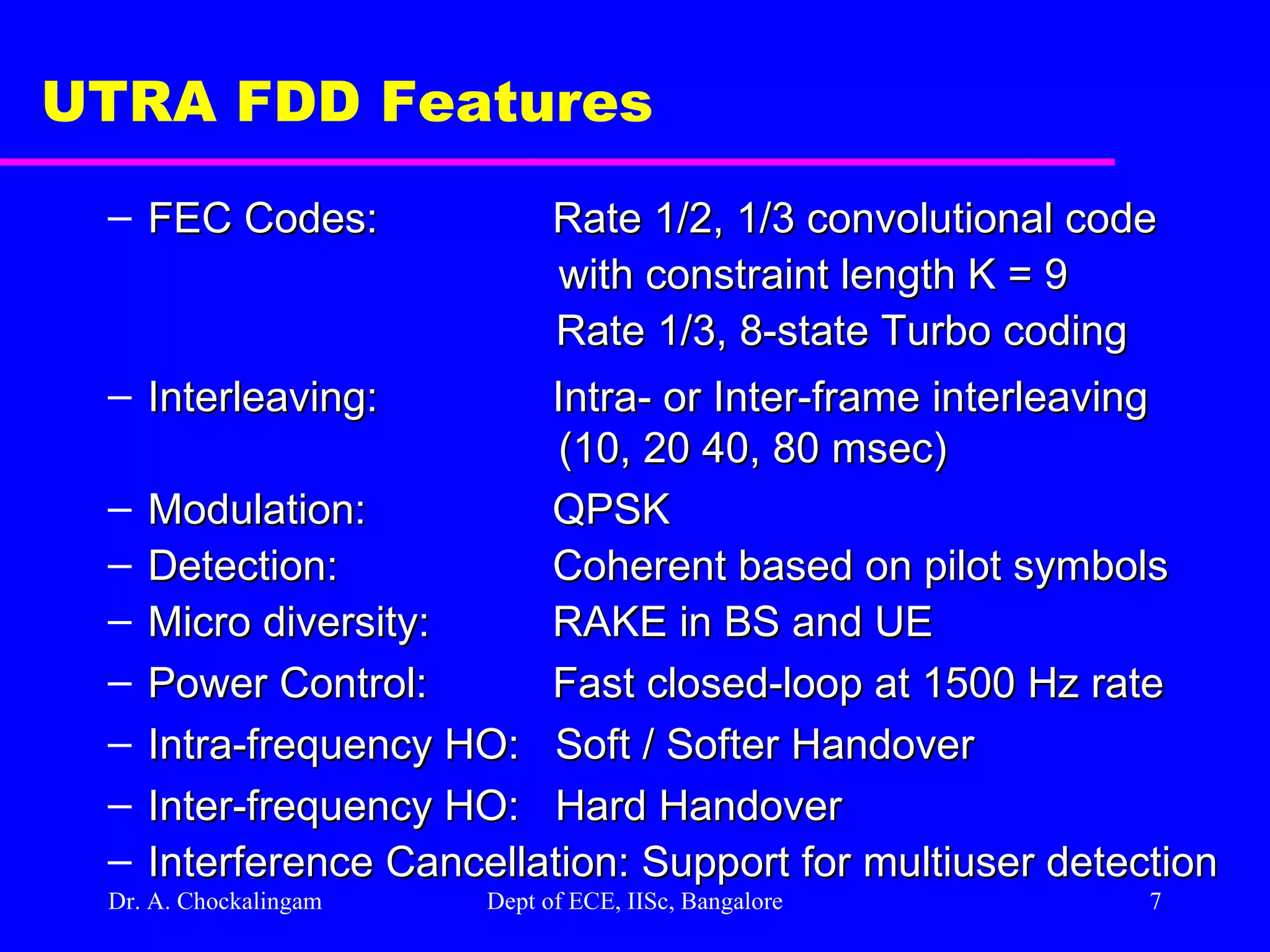
Dr. A. Chockalingam Dept of ECE, IISc, Bangalore UTRA FDD Features FEC Codes: Rate 1/2, 1/3 convolutional code with constraint length K = 9 Rate 1/3, 8-state Turbo coding Interleaving: Intra- or Inter-frame interleaving (10, 20 40, 80 msec) Modulation: QPSK Detection: Coherent based on pilot symbols Micro diversity: RAKE in BS and UE Power Control: Fast closed-loop at 1500 Hz rate Intra-frequency HO: Soft / Softer Handover Inter-frequency HO: Hard Handover Interference Cancellation: Support for multiuser detection
8.
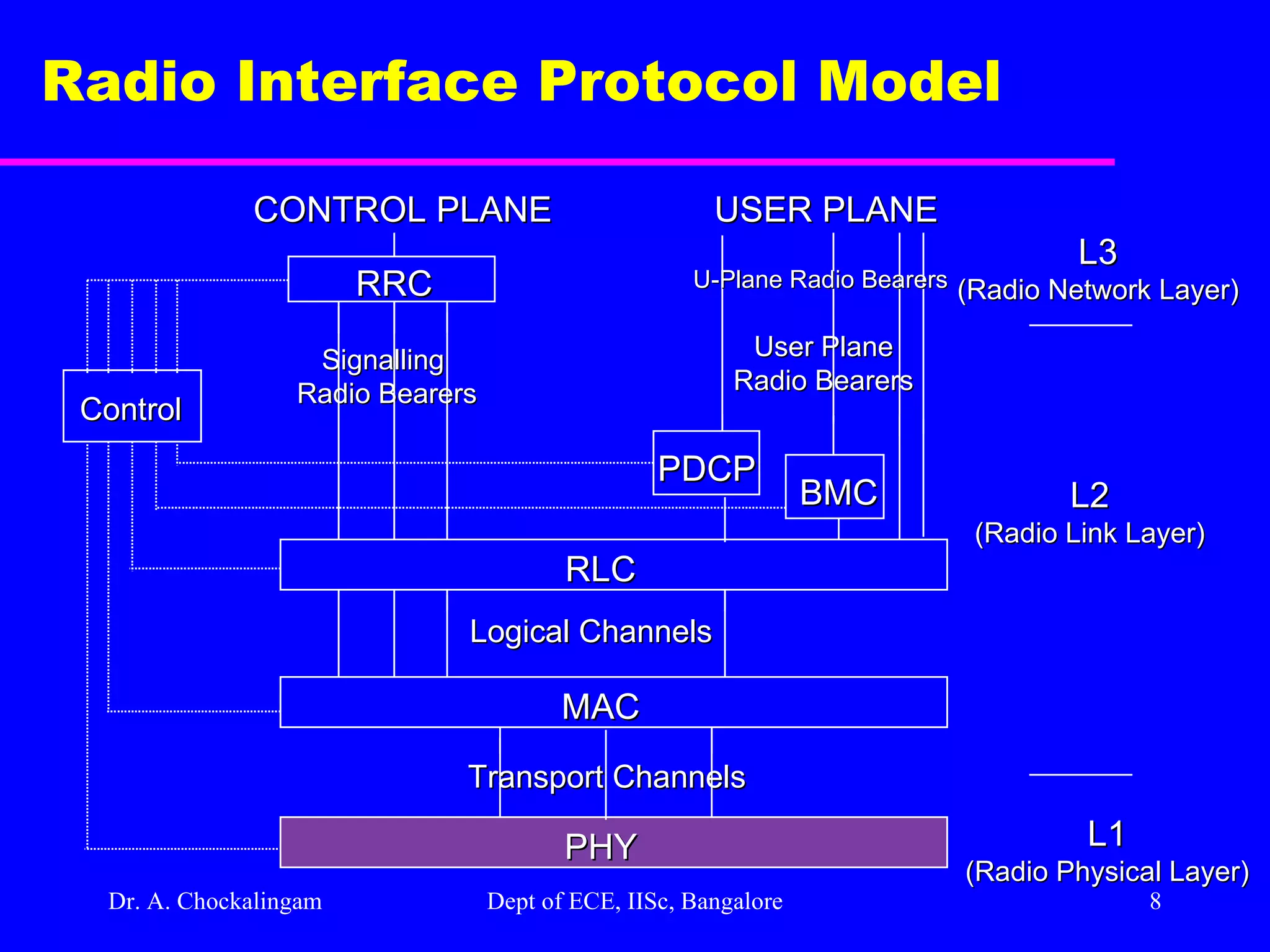
Dr. A. Chockalingam Dept of ECE, IISc, Bangalore Radio Interface Protocol Model PHY MAC RLC Transport Channels Logical Channels User Plane Radio Bearers Signalling Radio Bearers PDCP BMC RRC USER PLANE CONTROL PLANE Control L1 (Radio Physical Layer) L2 (Radio Link Layer) L3 (Radio Network Layer) U-Plane Radio Bearers
9.
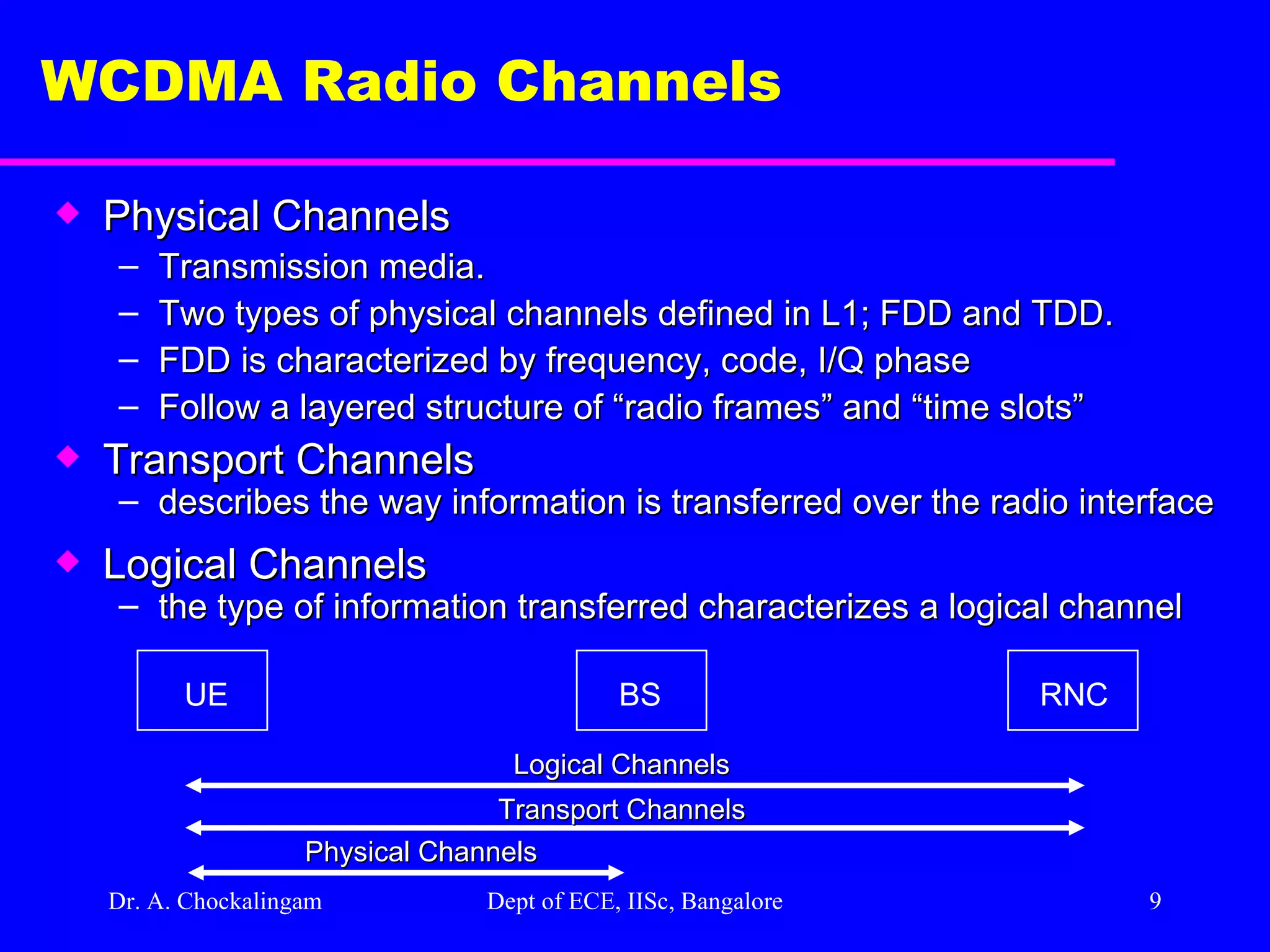
Dr. A. Chockalingam Dept of ECE, IISc, Bangalore WCDMA Radio Channels Physical Channels Transmission media. Two types of physical channels defined in L1; FDD and TDD. FDD is characterized by frequency, code, I/Q phase Follow a layered structure of “radio frames” and “time slots” Transport Channels describes the way information is transferred over the radio interface Logical Channels the type of information transferred characterizes a logical channel UE BS RNC Logical Channels Transport Channels Physical Channels
10.
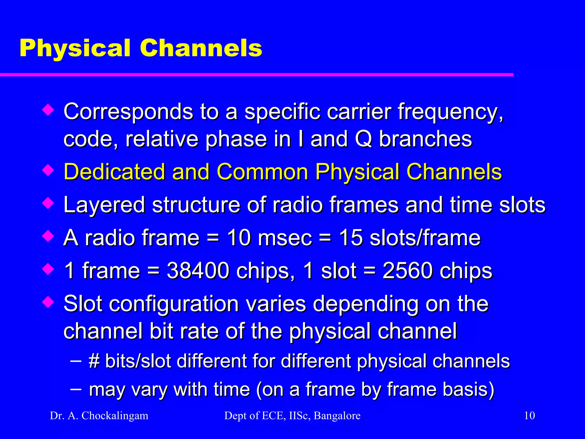
Dr. A. Chockalingam Dept of ECE, IISc, Bangalore Physical Channels Corresponds to a specific carrier frequency, code, relative phase in I and Q branches Dedicated and Common Physical Channels Layered structure of radio frames and time slots A radio frame = 10 msec = 15 slots/frame 1 frame = 38400 chips, 1 slot = 2560 chips Slot configuration varies depending on the channel bit rate of the physical channel # bits/slot different for different physical channels may vary with time (on a frame by frame basis)
11.
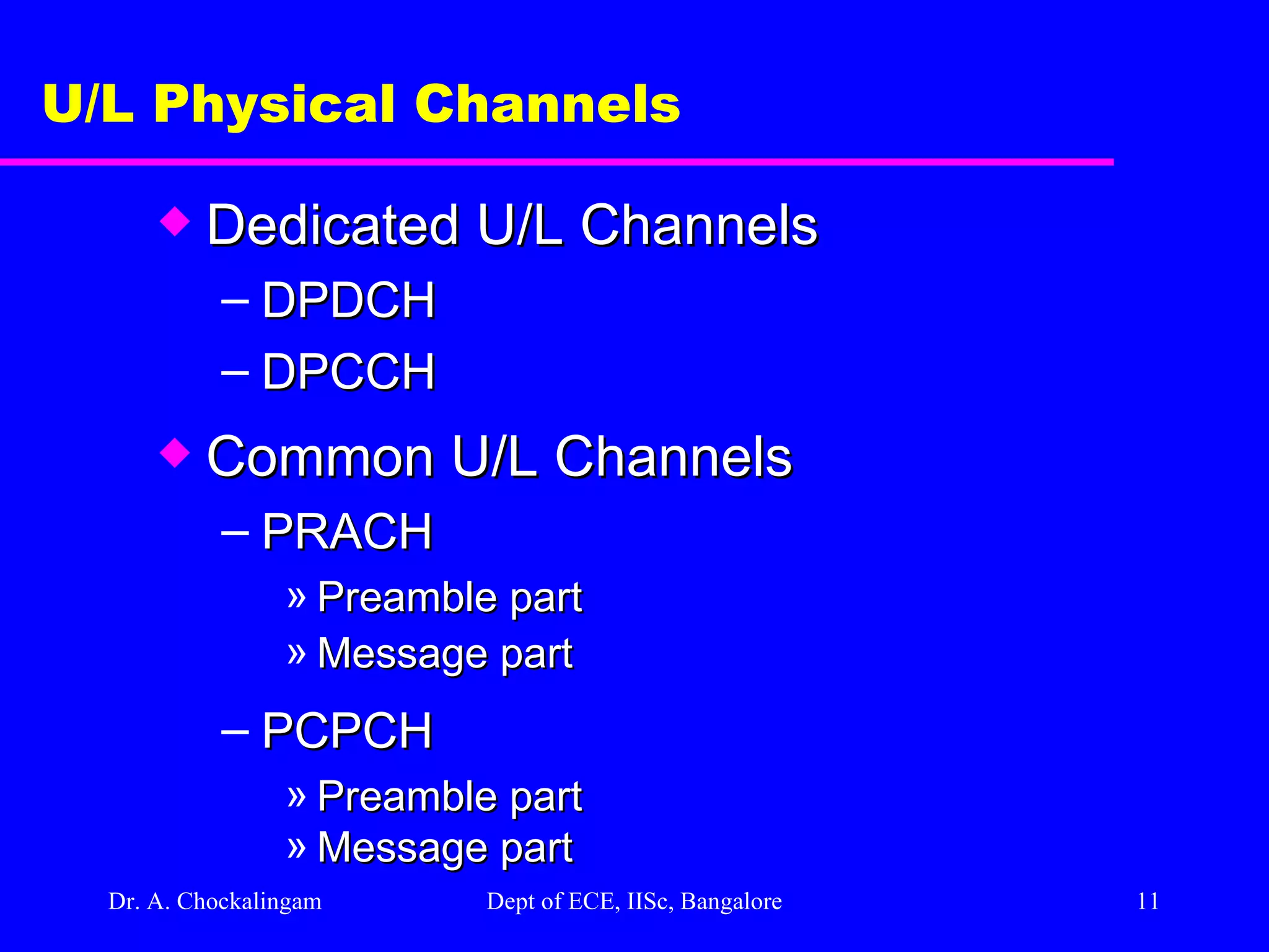
Dr. A. Chockalingam Dept of ECE, IISc, Bangalore U/L Physical Channels Dedicated U/L Channels DPDCH DPCCH Common U/L Channels PRACH Preamble part Message part PCPCH Preamble part Message part
12.
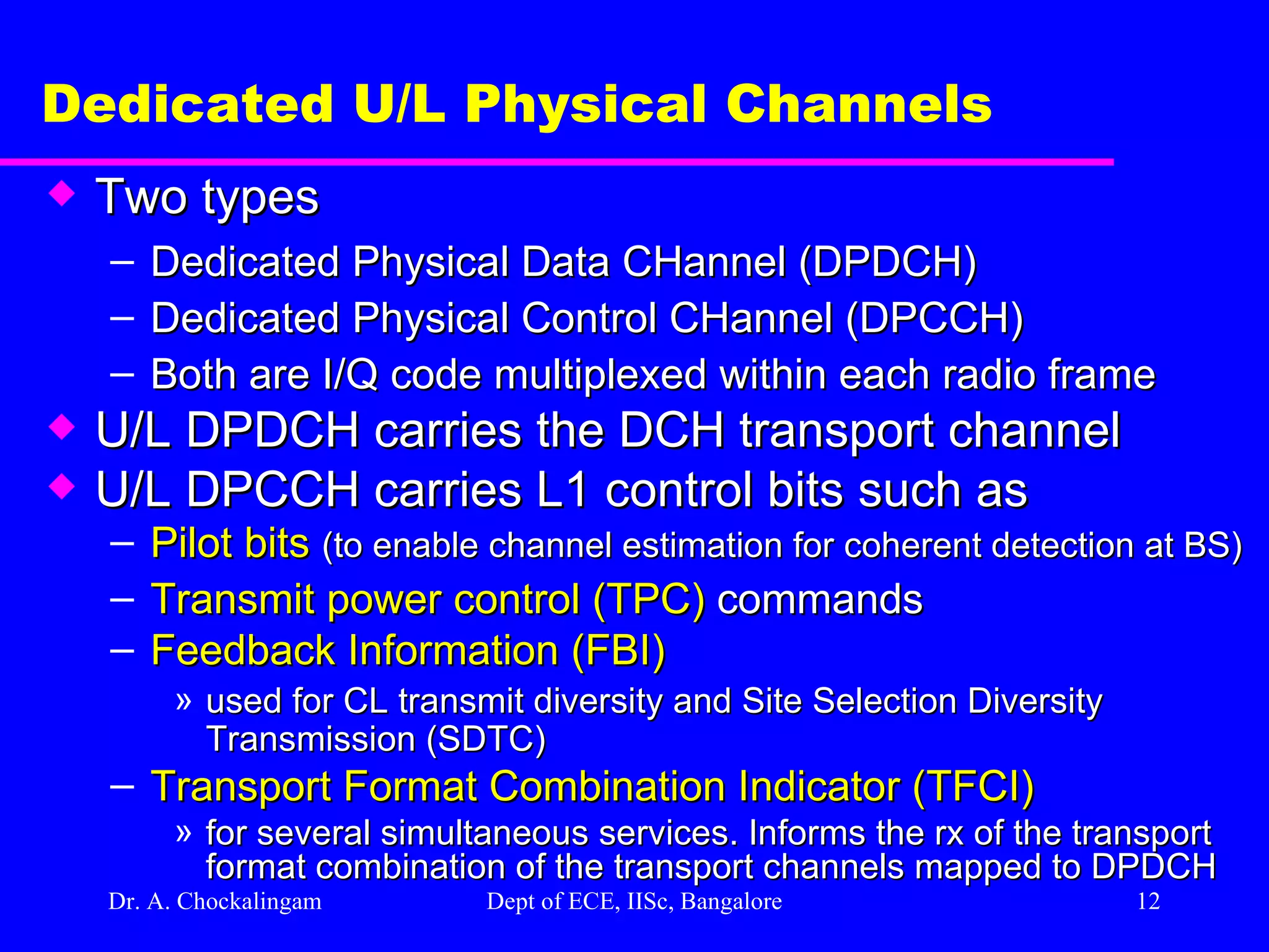
Dr. A. Chockalingam Dept of ECE, IISc, Bangalore Dedicated U/L Physical Channels Two types Dedicated Physical Data CHannel (DPDCH) Dedicated Physical Control CHannel (DPCCH) Both are I/Q code multiplexed within each radio frame U/L DPDCH carries the DCH transport channel U/L DPCCH carries L1 control bits such as Pilot bits (to enable channel estimation for coherent detection at BS) Transmit power control (TPC) commands Feedback Information (FBI) used for CL transmit diversity and Site Selection Diversity Transmission (SDTC) Transport Format Combination Indicator (TFCI) for several simultaneous services. Informs the rx of the transport format combination of the transport channels mapped to DPDCH
13.
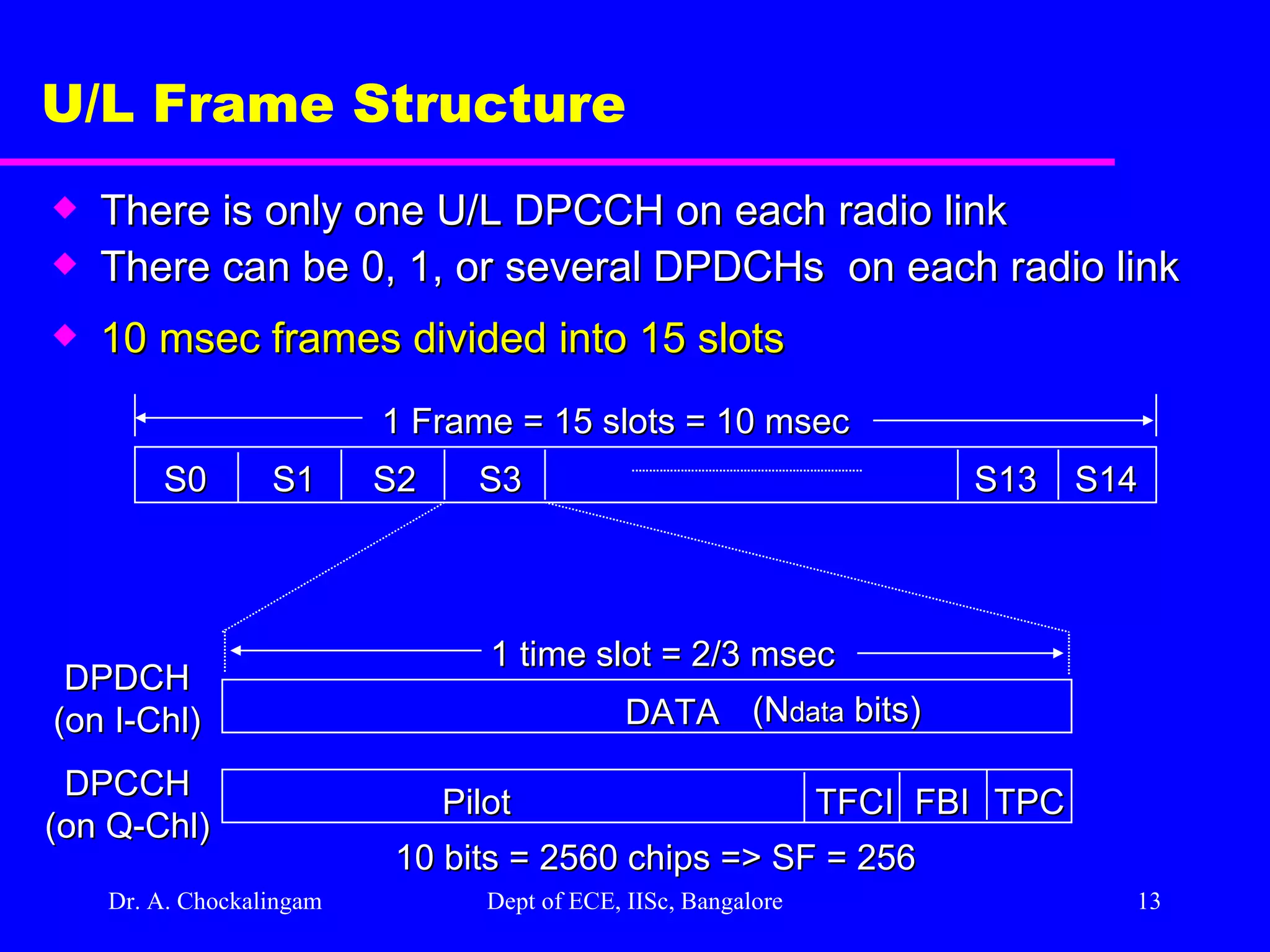
Dr. A. Chockalingam Dept of ECE, IISc, Bangalore U/L Frame Structure There is only one U/L DPCCH on each radio link There can be 0, 1, or several DPDCHs on each radio link 10 msec frames divided into 15 slots S0 S1 S2 S3 S13 S14 1 Frame = 15 slots = 10 msec DATA 1 time slot = 2/3 msec DPDCH (on I-Chl) Pilot DPCCH (on Q-Chl) TFCI FBI TPC 10 bits = 2560 chips => SF = 256 (N data bits)
14.
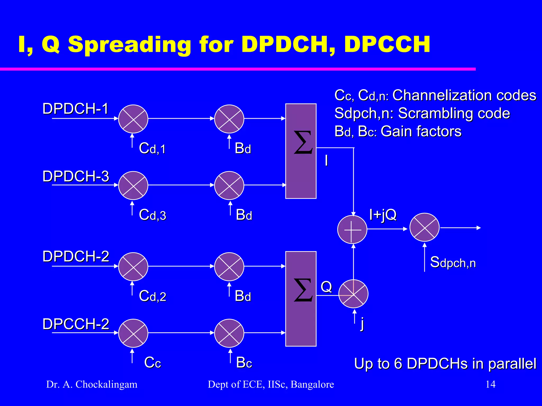
Dr. A. Chockalingam Dept of ECE, IISc, Bangalore I, Q Spreading for DPDCH, DPCCH DPDCH-1 DPDCH-3 C d,1 C d,3 B d B d I DPDCH-2 DPCCH-2 C d,2 C c B c B d Q I+jQ S dpch,n C c, C d,n: Channelization codes Sdpch,n: Scrambling code B d, B c: Gain factors Up to 6 DPDCHs in parallel j
15.
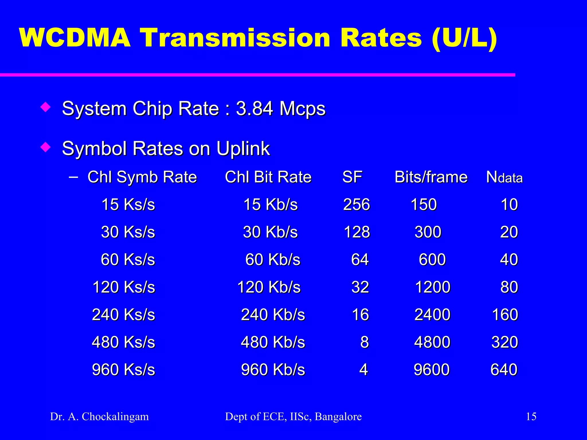
Dr. A. Chockalingam Dept of ECE, IISc, Bangalore WCDMA Transmission Rates (U/L) System Chip Rate : 3.84 Mcps Symbol Rates on Uplink Chl Symb Rate Chl Bit Rate SF Bits/frame N data 15 Ks/s 15 Kb/s 256 150 10 30 Ks/s 30 Kb/s 128 300 20 60 Ks/s 60 Kb/s 64 600 40 120 Ks/s 120 Kb/s 32 1200 80 240 Ks/s 240 Kb/s 16 2400 160 480 Ks/s 480 Kb/s 8 4800 320 960 Ks/s 960 Kb/s 4 9600 640
16.
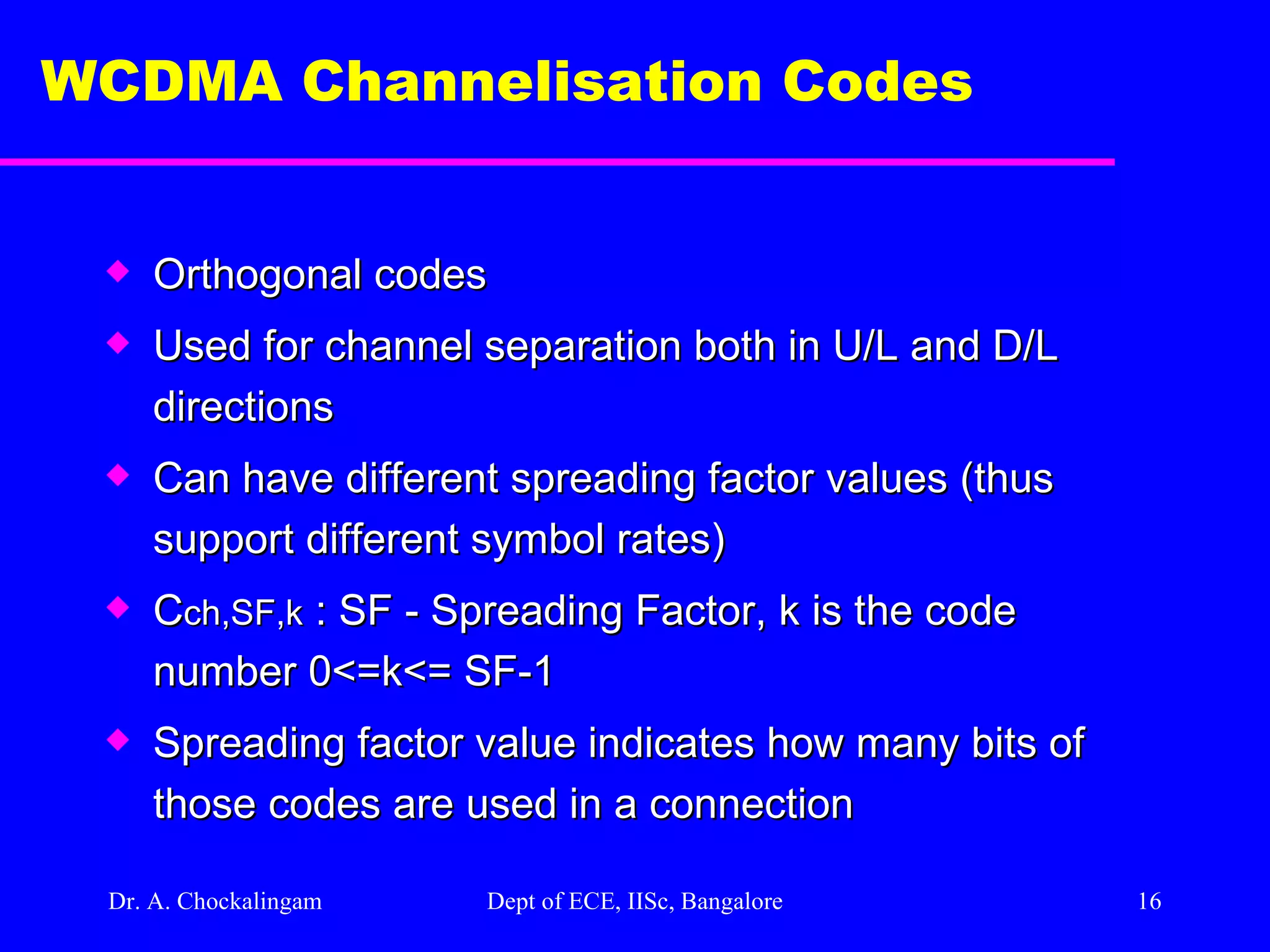
Dr. A. Chockalingam Dept of ECE, IISc, Bangalore WCDMA Channelisation Codes Orthogonal codes Used for channel separation both in U/L and D/L directions Can have different spreading factor values (thus support different symbol rates) C ch,SF,k : SF - Spreading Factor, k is the code number 0<=k<= SF-1 Spreading factor value indicates how many bits of those codes are used in a connection
17.
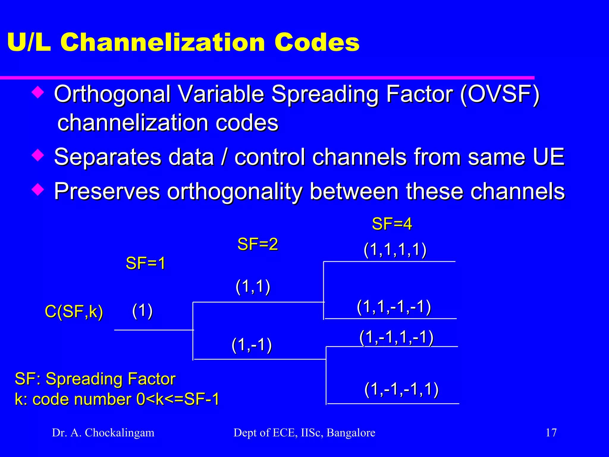
Dr. A. Chockalingam Dept of ECE, IISc, Bangalore U/L Channelization Codes Orthogonal Variable Spreading Factor (OVSF) channelization codes Separates data / control channels from same UE Preserves orthogonality between these channels (1) (1,1) (1,-1) (1,1,1,1) (1,1,-1,-1) (1,-1,1,-1) (1,-1,-1,1) SF=1 SF=2 SF=4 C(SF,k) SF: Spreading Factor k: code number 0<k<=SF-1
18.
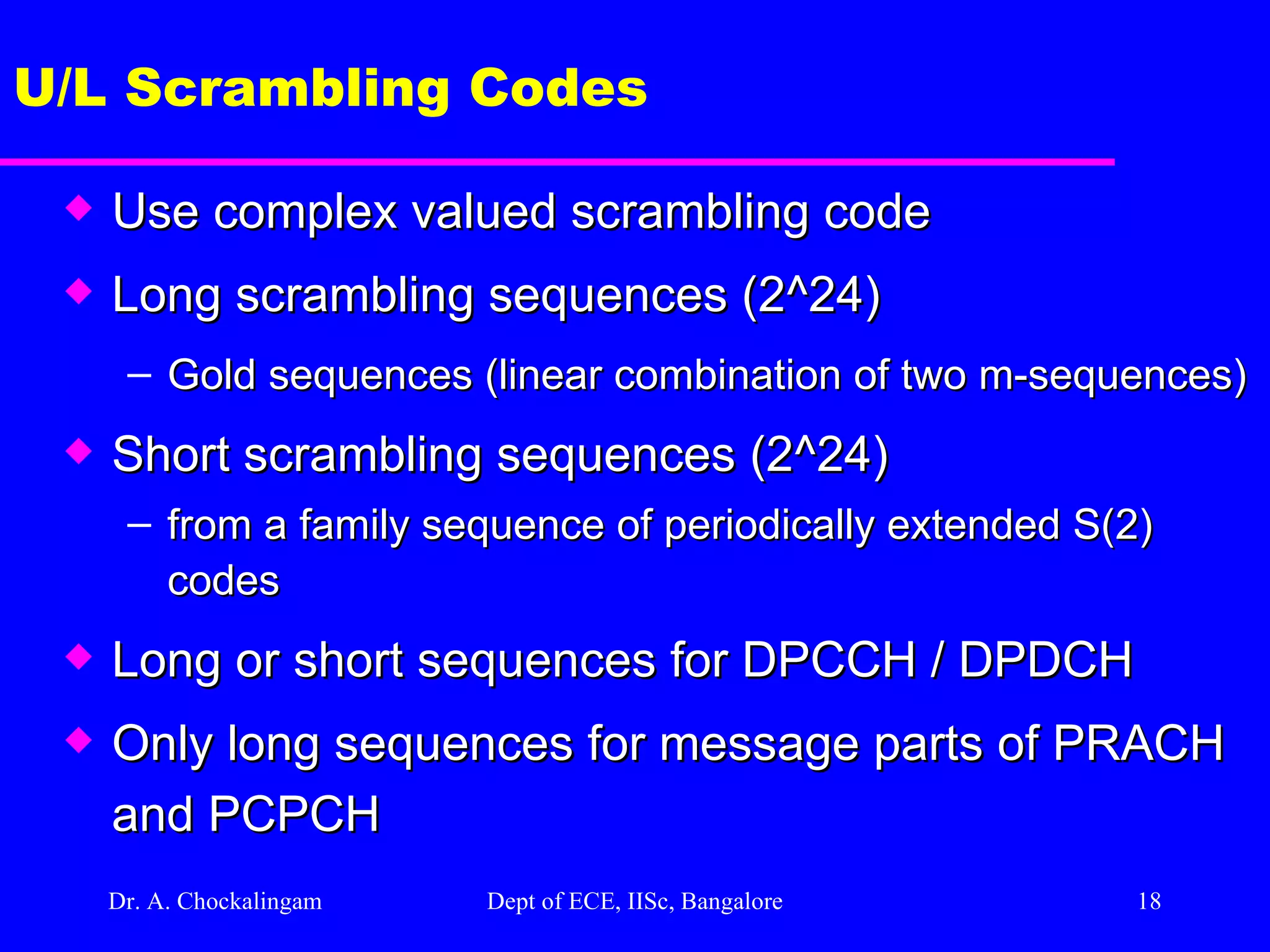
Dr. A. Chockalingam Dept of ECE, IISc, Bangalore U/L Scrambling Codes Use complex valued scrambling code Long scrambling sequences (2^24) Gold sequences (linear combination of two m-sequences) Short scrambling sequences (2^24) from a family sequence of periodically extended S(2) codes Long or short sequences for DPCCH / DPDCH Only long sequences for message parts of PRACH and PCPCH
19.
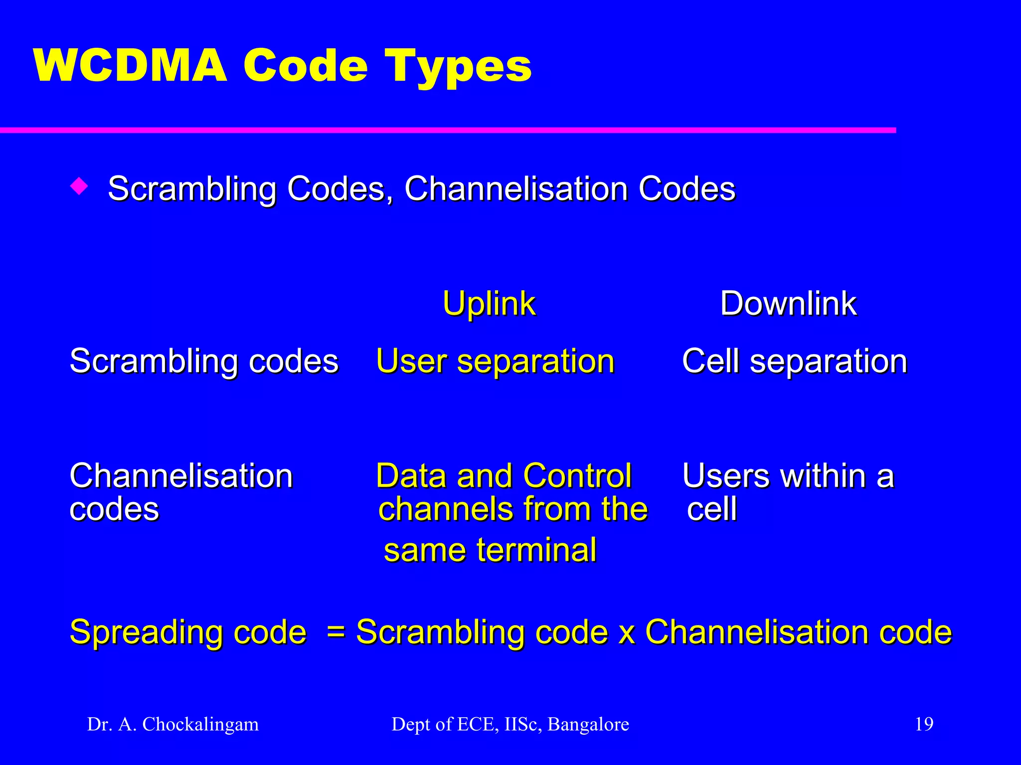
Dr. A. Chockalingam Dept of ECE, IISc, Bangalore WCDMA Code Types Scrambling Codes, Channelisation Codes Uplink Downlink Scrambling codes User separation Cell separation Channelisation Data and Control Users within a codes channels from the cell same terminal Spreading code = Scrambling code x Channelisation code
20.
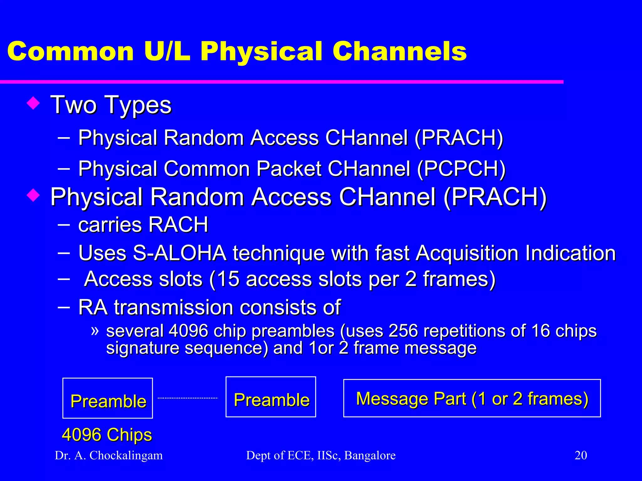
Dr. A. Chockalingam Dept of ECE, IISc, Bangalore Common U/L Physical Channels Two Types Physical Random Access CHannel (PRACH) Physical Common Packet CHannel (PCPCH) Physical Random Access CHannel (PRACH) carries RACH Uses S-ALOHA technique with fast Acquisition Indication Access slots (15 access slots per 2 frames) RA transmission consists of several 4096 chip preambles (uses 256 repetitions of 16 chips signature sequence) and 1or 2 frame message Preamble Message Part (1 or 2 frames) 4096 Chips Preamble
21.
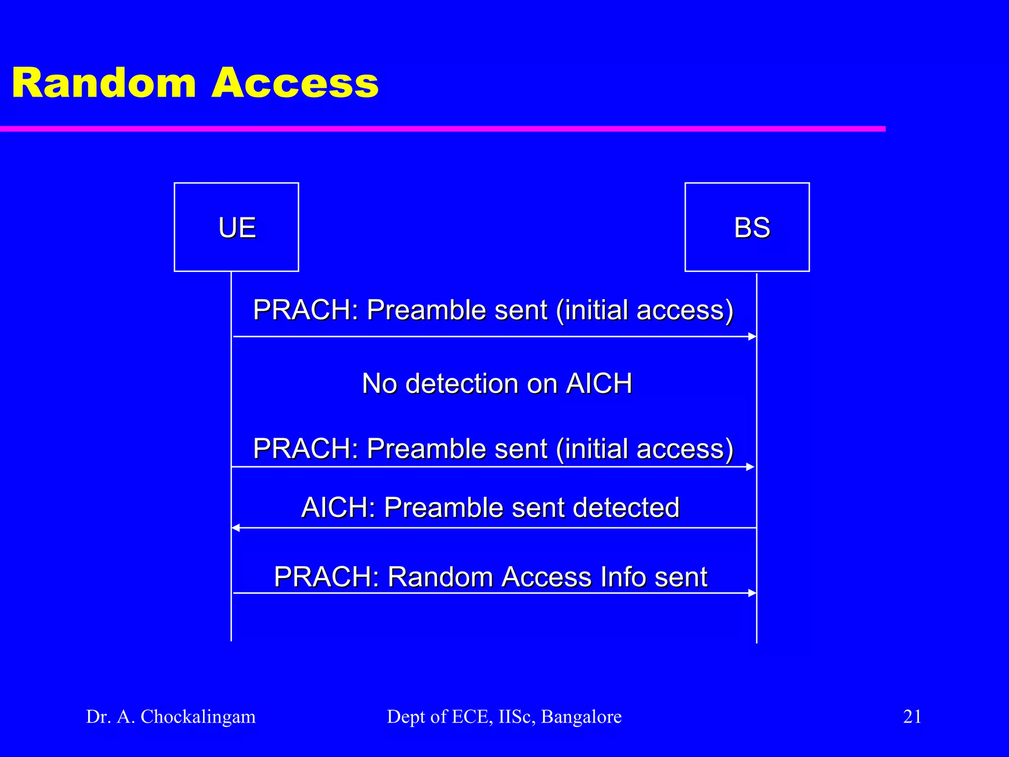
Dr. A. Chockalingam Dept of ECE, IISc, Bangalore Random Access UE BS PRACH: Preamble sent (initial access) No detection on AICH PRACH: Preamble sent (initial access) AICH: Preamble sent detected PRACH: Random Access Info sent
22.
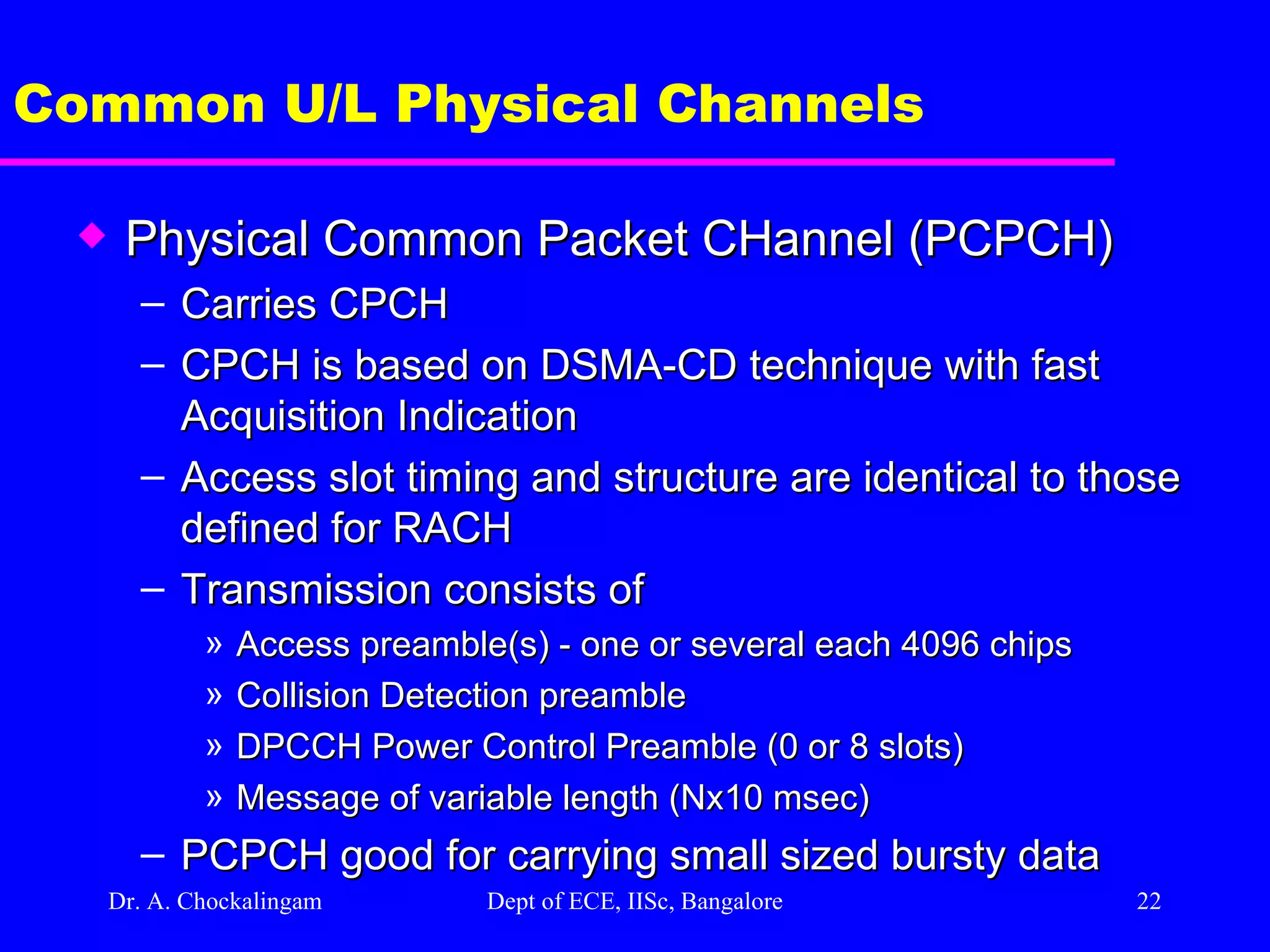
Dr. A. Chockalingam Dept of ECE, IISc, Bangalore Common U/L Physical Channels Physical Common Packet CHannel (PCPCH) Carries CPCH CPCH is based on DSMA-CD technique with fast Acquisition Indication Access slot timing and structure are identical to those defined for RACH Transmission consists of Access preamble(s) - one or several each 4096 chips Collision Detection preamble DPCCH Power Control Preamble (0 or 8 slots) Message of variable length (Nx10 msec) PCPCH good for carrying small sized bursty data
23.
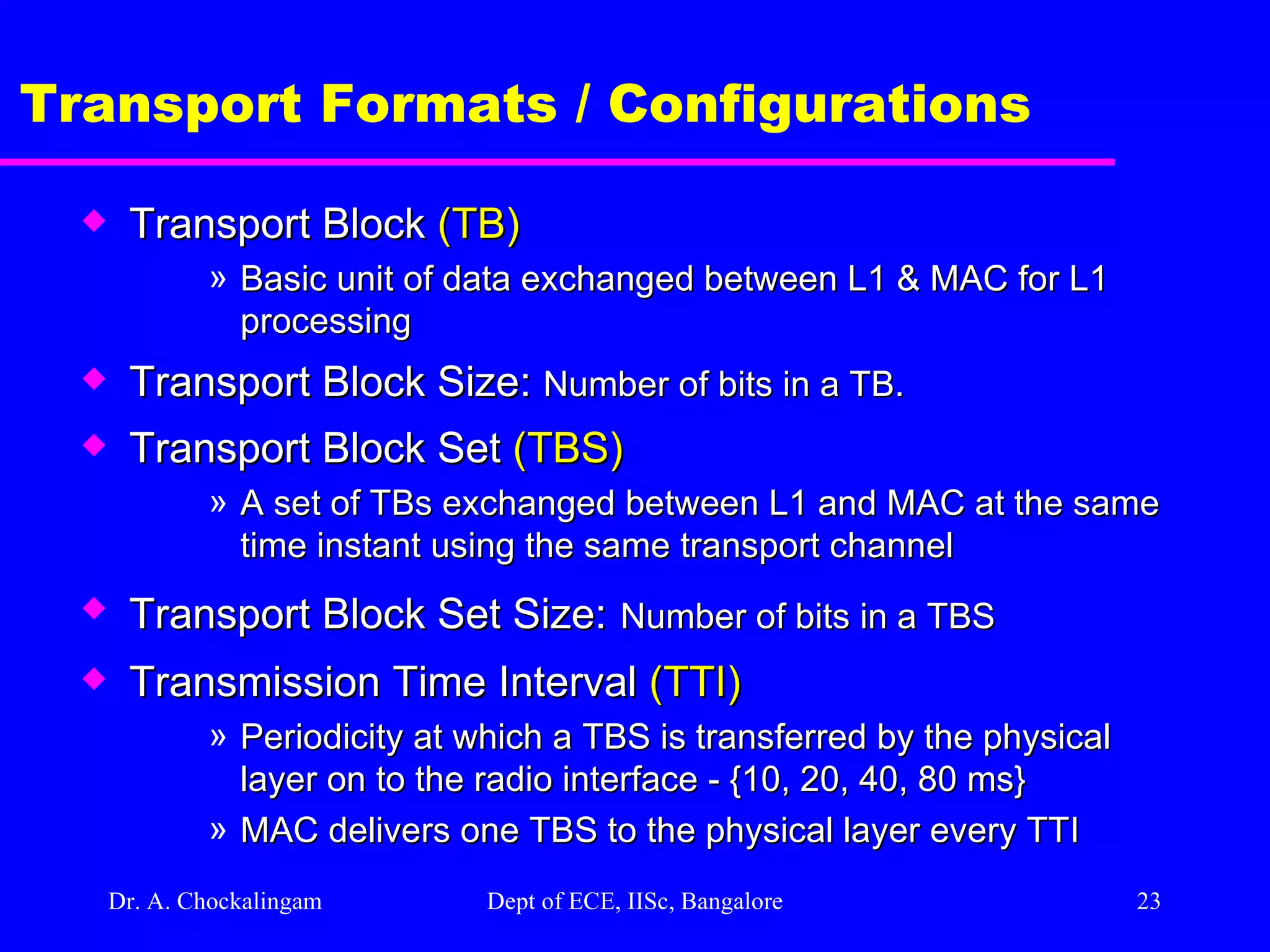
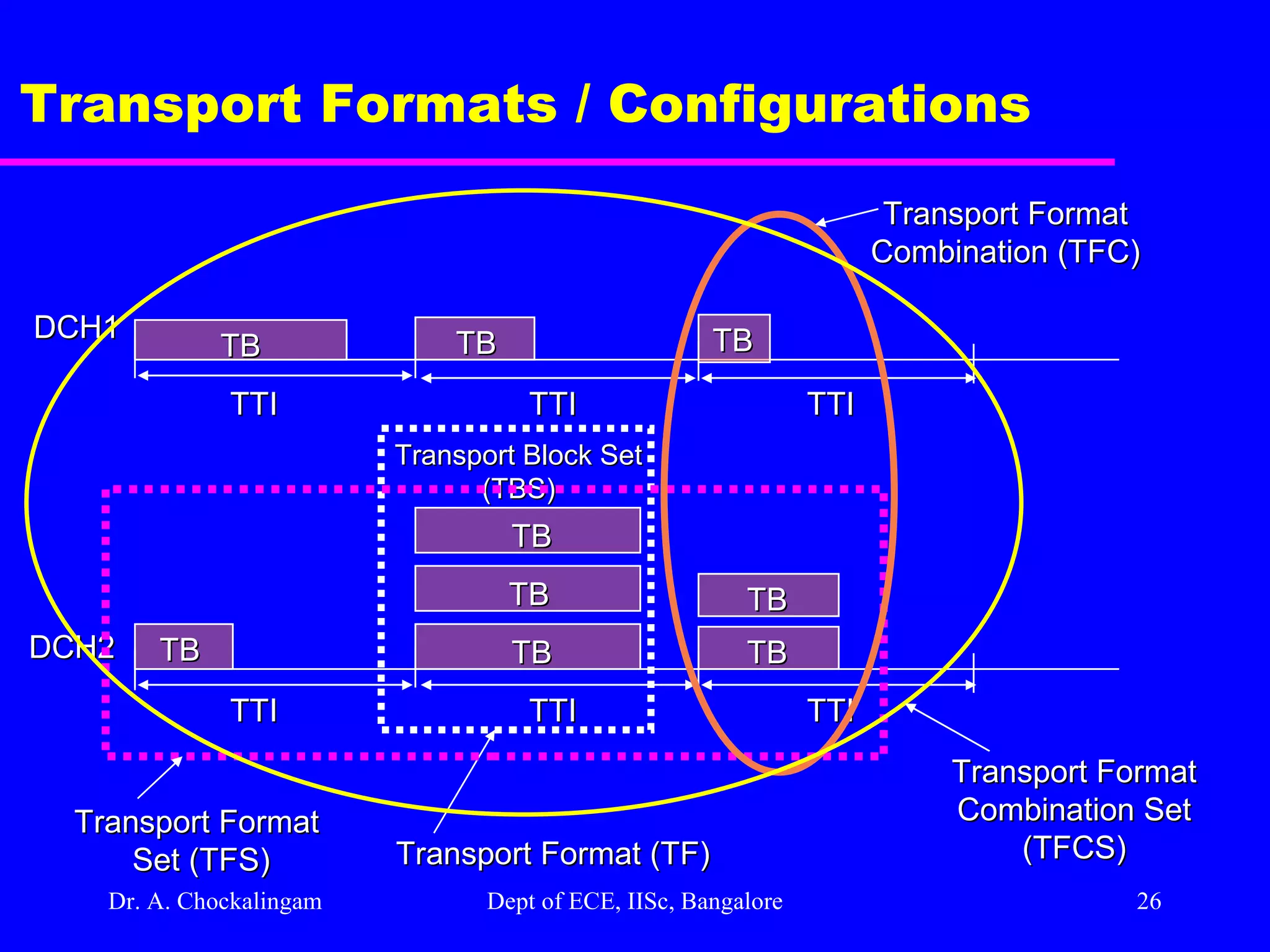
Dr. A. Chockalingam Dept of ECE, IISc, Bangalore Transport Formats / Configurations Transport Block (TB) Basic unit of data exchanged between L1 & MAC for L1 processing Transport Block Size: Number of bits in a TB. Transport Block Set (TBS) A set of TBs exchanged between L1 and MAC at the same time instant using the same transport channel Transport Block Set Size: Number of bits in a TBS Transmission Time Interval (TTI) Periodicity at which a TBS is transferred by the physical layer on to the radio interface - {10, 20, 40, 80 ms} MAC delivers one TBS to the physical layer every TTI
24.
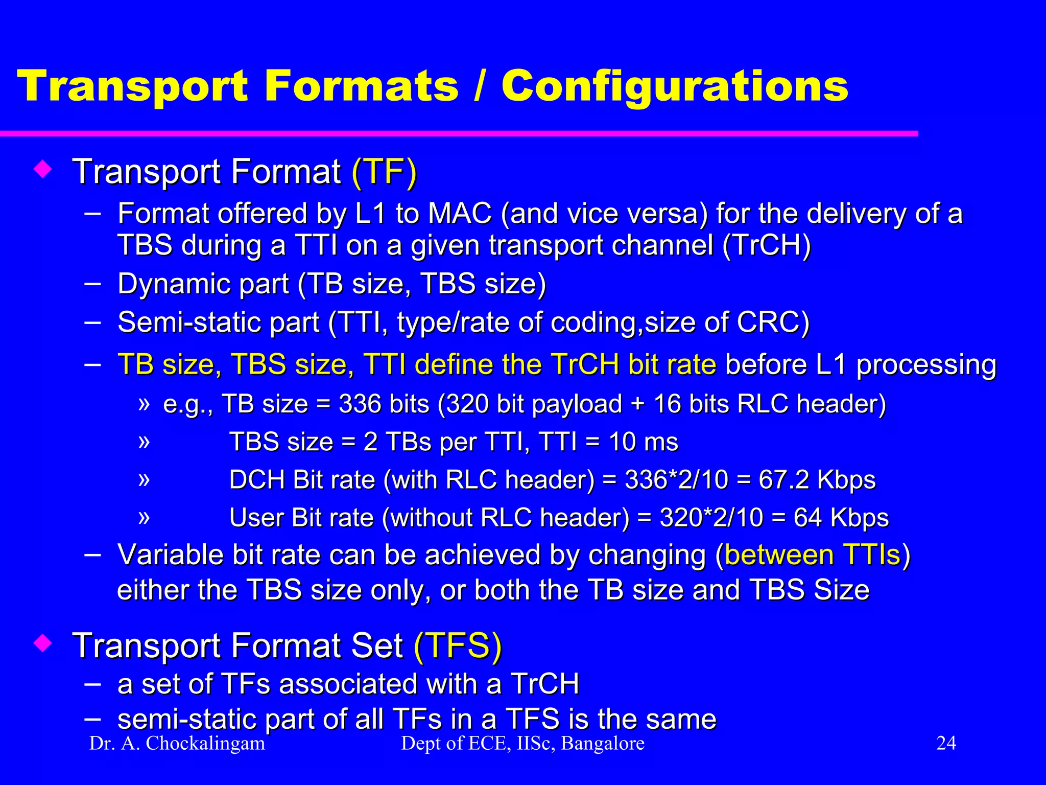
Dr. A. Chockalingam Dept of ECE, IISc, Bangalore Transport Formats / Configurations Transport Format (TF) Format offered by L1 to MAC (and vice versa) for the delivery of a TBS during a TTI on a given transport channel (TrCH) Dynamic part (TB size, TBS size) Semi-static part (TTI, type/rate of coding,size of CRC) TB size, TBS size, TTI define the TrCH bit rate before L1 processing e.g., TB size = 336 bits (320 bit payload + 16 bits RLC header) TBS size = 2 TBs per TTI, TTI = 10 ms DCH Bit rate (with RLC header) = 336*2/10 = 67.2 Kbps User Bit rate (without RLC header) = 320*2/10 = 64 Kbps Variable bit rate can be achieved by changing ( between TTIs ) either the TBS size only, or both the TB size and TBS Size Transport Format Set (TFS) a set of TFs associated with a TrCH semi-static part of all TFs in a TFS is the same
25.
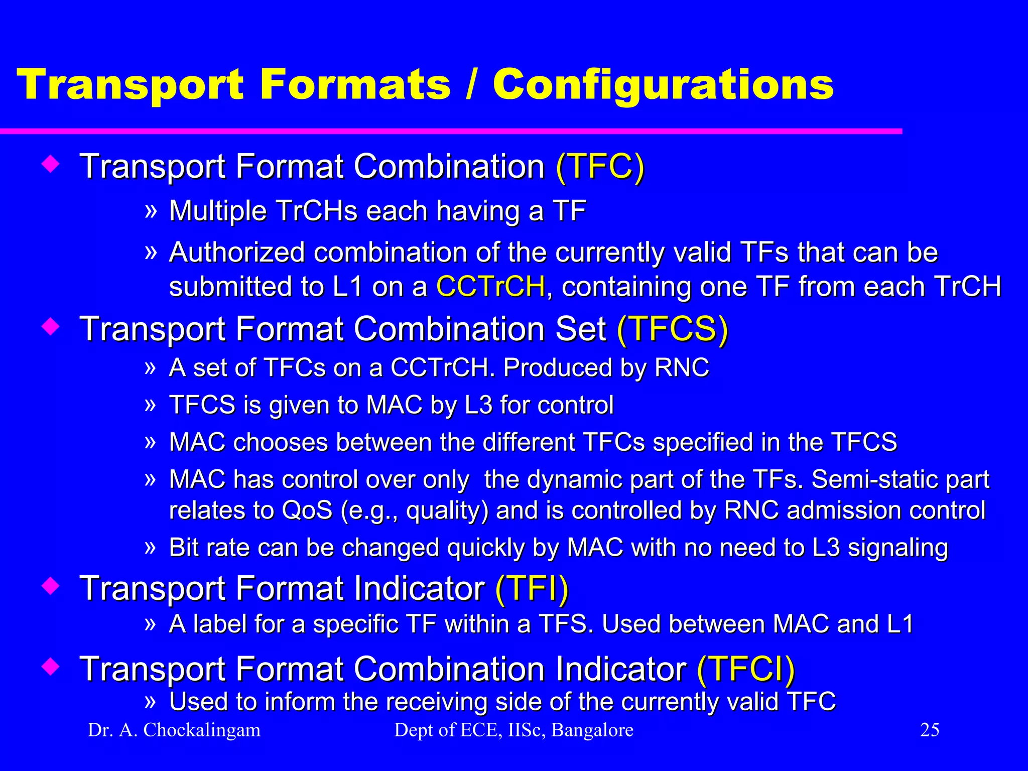
Dr. A. Chockalingam Dept of ECE, IISc, Bangalore Transport Formats / Configurations Transport Format Combination (TFC) Multiple TrCHs each having a TF Authorized combination of the currently valid TFs that can be submitted to L1 on a CCTrCH , containing one TF from each TrCH Transport Format Combination Set (TFCS) A set of TFCs on a CCTrCH. Produced by RNC TFCS is given to MAC by L3 for control MAC chooses between the different TFCs specified in the TFCS MAC has control over only the dynamic part of the TFs. Semi-static part relates to QoS (e.g., quality) and is controlled by RNC admission control Bit rate can be changed quickly by MAC with no need to L3 signaling Transport Format Indicator (TFI) A label for a specific TF within a TFS. Used between MAC and L1 Transport Format Combination Indicator (TFCI) Used to inform the receiving side of the currently valid TFC
26.
Dr. A. Chockalingam Dept of ECE, IISc, Bangalore Transport Formats / Configurations TTI TTI TTI TTI TTI TTI TB DCH1 DCH2 TB TB TB TB TB TB Transport Block Set (TBS) TB TB Transport Format (TF) Transport Format Set (TFS) Transport Format Combination (TFC) Transport Format Combination Set (TFCS)
27.
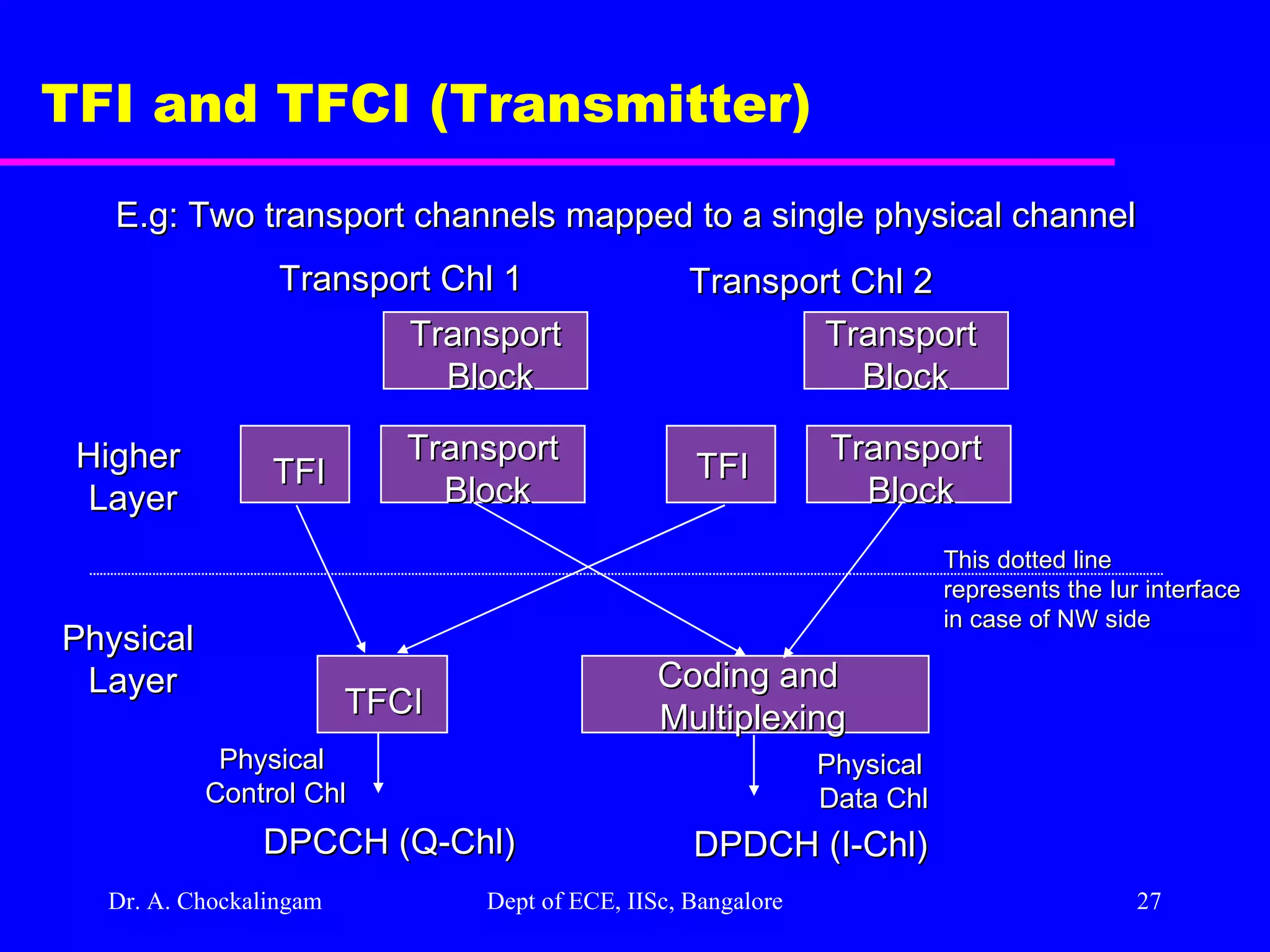
Dr. A. Chockalingam Dept of ECE, IISc, Bangalore TFI and TFCI (Transmitter) Transport Chl 1 Transport Chl 2 Transport Block Transport Block Transport Block Transport Block TFI TFI TFCI Coding and Multiplexing Physical Layer Higher Layer DPCCH (Q-Chl) DPDCH (I-Chl) Physical Control Chl Physical Data Chl E.g: Two transport channels mapped to a single physical channel This dotted line represents the Iur interface in case of NW side
28.
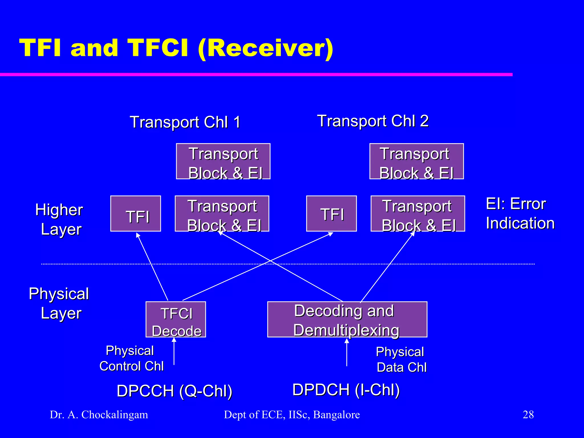
Dr. A. Chockalingam Dept of ECE, IISc, Bangalore TFI and TFCI (Receiver) Transport Chl 1 Transport Chl 2 Transport Block & EI Transport Block & EI Transport Block & EI Transport Block & EI TFI TFI TFCI Decode Decoding and Demultiplexing Physical Layer Higher Layer DPCCH (Q-Chl) DPDCH (I-Chl) EI: Error Indication Physical Control Chl Physical Data Chl
29.
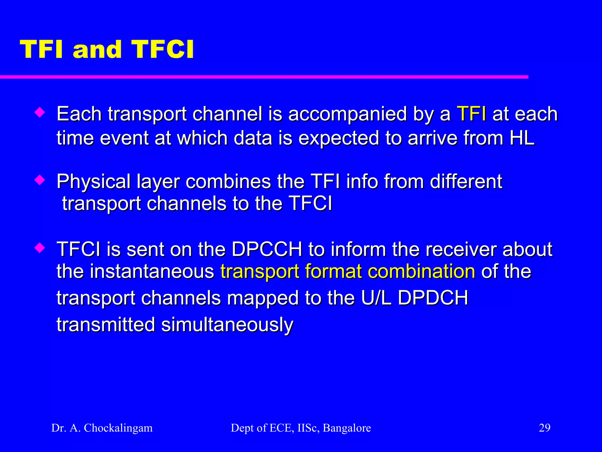
Dr. A. Chockalingam Dept of ECE, IISc, Bangalore TFI and TFCI Each transport channel is accompanied by a TFI at each time event at which data is expected to arrive from HL Physical layer combines the TFI info from different transport channels to the TFCI TFCI is sent on the DPCCH to inform the receiver about the instantaneous transport format combination of the transport channels mapped to the U/L DPDCH transmitted simultaneously
30.
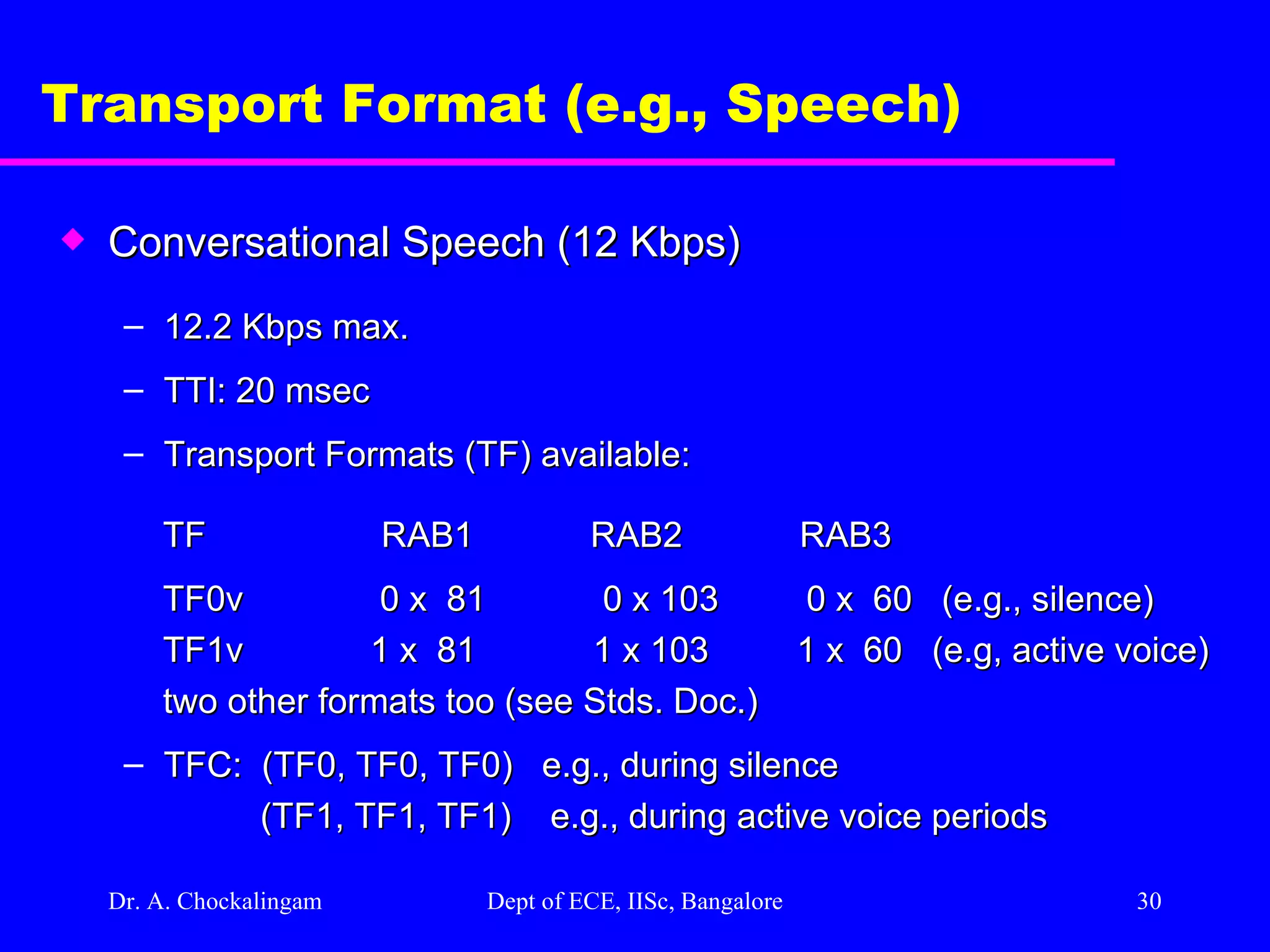
Dr. A. Chockalingam Dept of ECE, IISc, Bangalore Transport Format (e.g., Speech) Conversational Speech (12 Kbps) 12.2 Kbps max. TTI: 20 msec Transport Formats (TF) available: TF RAB1 RAB2 RAB3 TF0v 0 x 81 0 x 103 0 x 60 (e.g., silence) TF1v 1 x 81 1 x 10³ 1 x 60 (e.g, active voice) two other formats too (see Stds. Doc.) TFC: (TF0, TF0, TF0) e.g., during silence (TF1, TF1, TF1) e.g., during active voice periods
31.
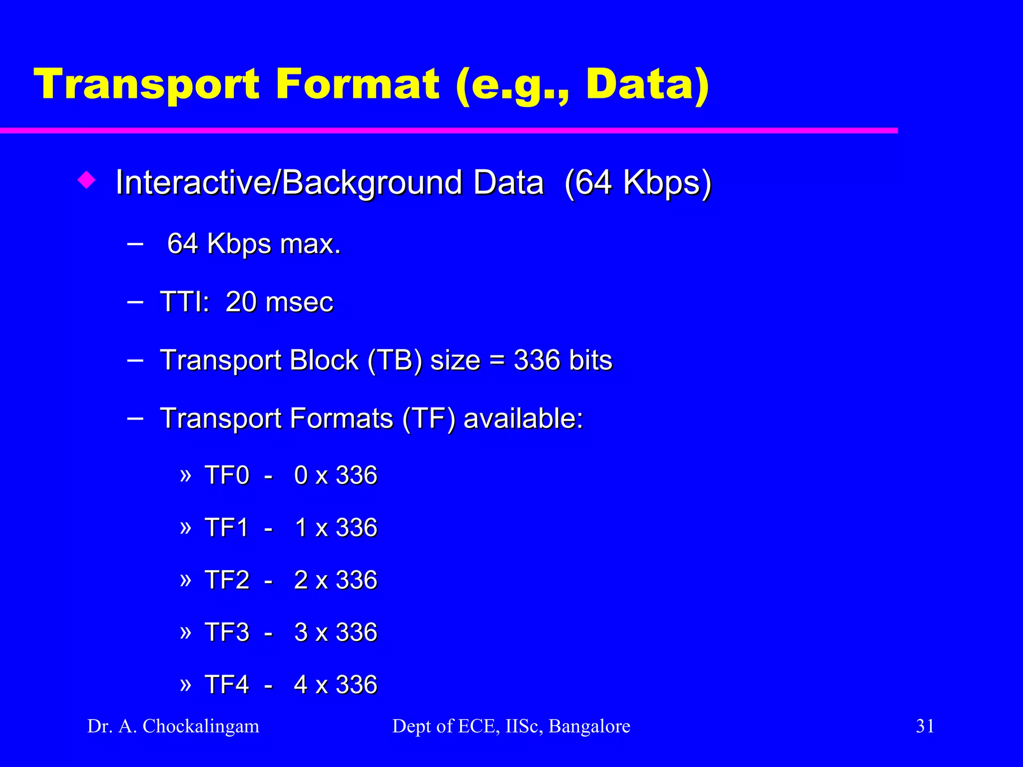
Dr. A. Chockalingam Dept of ECE, IISc, Bangalore Transport Format (e.g., Data) Interactive/Background Data (64 Kbps) 64 Kbps max. TTI: 20 msec Transport Block (TB) size = 336 bits Transport Formats (TF) available: TF0 - 0 x 336 TF1 - 1 x 336 TF2 - 2 x 336 TF3 - 3 x 336 TF4 - 4 x 336
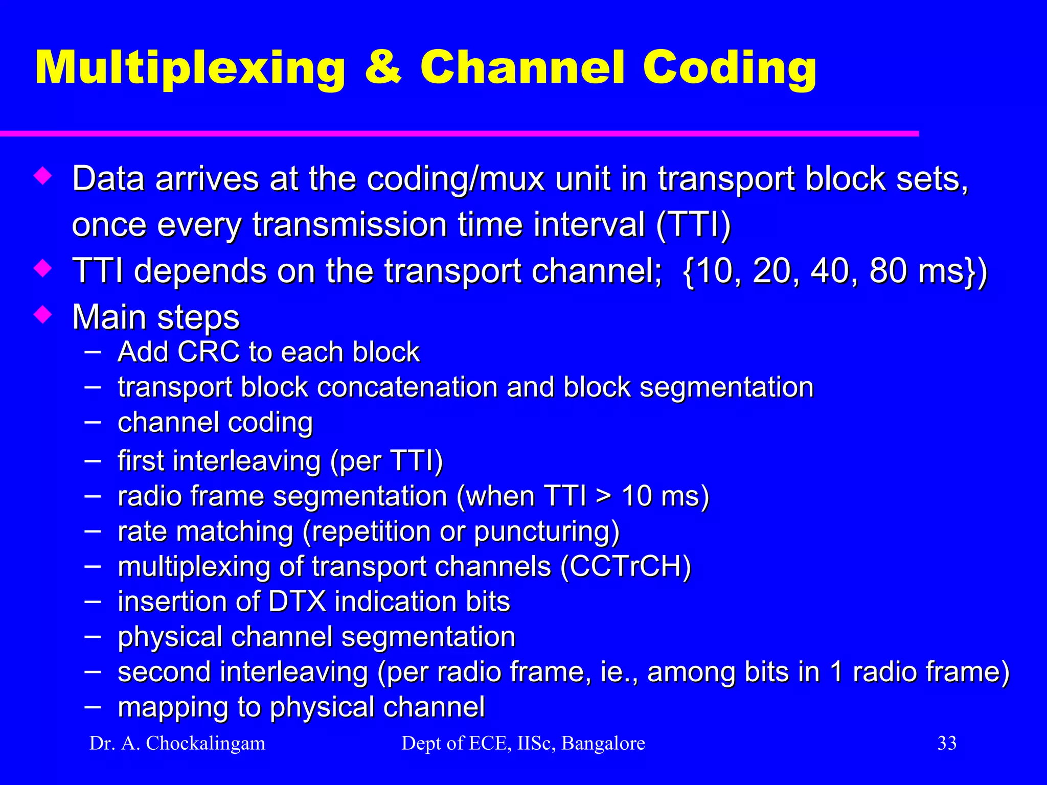
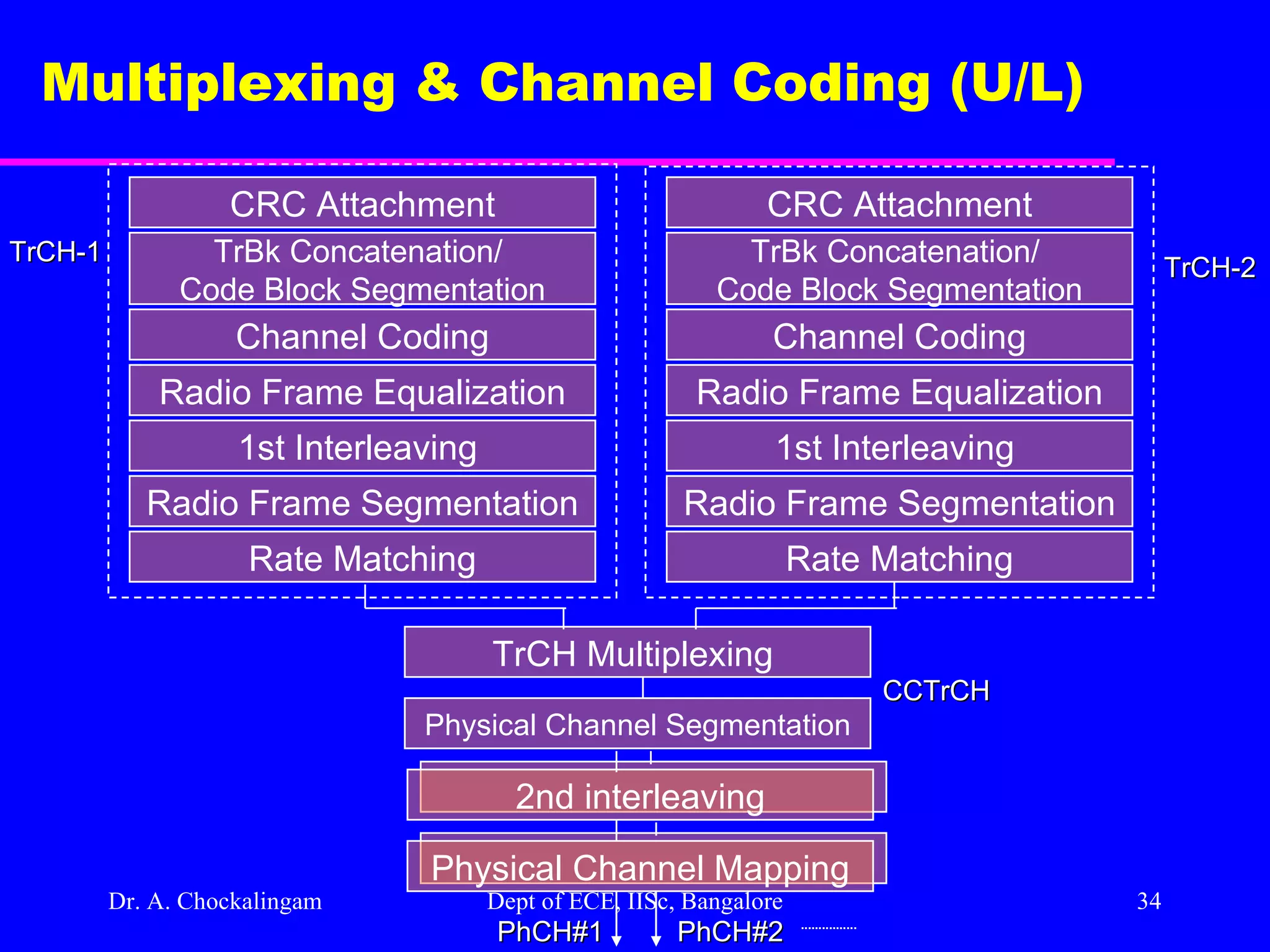
Dr. A. Chockalingam Dept of ECE, IISc, Bangalore Multiplexing & Channel Coding Data arrives at the coding/mux unit in transport block sets, once every transmission time interval (TTI) TTI depends on the transport channel; {10, 20, 40, 80 ms}) Main steps Add CRC to each block transport block concatenation and block segmentation channel coding first interleaving (per TTI) radio frame segmentation (when TTI > 10 ms) rate matching (repetition or puncturing) multiplexing of transport channels (CCTrCH) insertion of DTX indication bits physical channel segmentation second interleaving (per radio frame, ie., among bits in 1 radio frame) mapping to physical channel
34.
Dr. A. Chockalingam Dept of ECE, IISc, Bangalore Multiplexing & Channel Coding (U/L) CRC Attachment TrBk Concatenation/ Code Block Segmentation Channel Coding Radio Frame Equalization 1st Interleaving Radio Frame Segmentation Rate Matching CCTrCH CRC Attachment TrBk Concatenation/ Code Block Segmentation Channel Coding Radio Frame Equalization 1st Interleaving Radio Frame Segmentation Rate Matching TrCH-2 TrCH Multiplexing Physical Channel Segmentation 2nd interleaving TrCH-1 Physical Channel Mapping PhCH#2 PhCH#1
35.
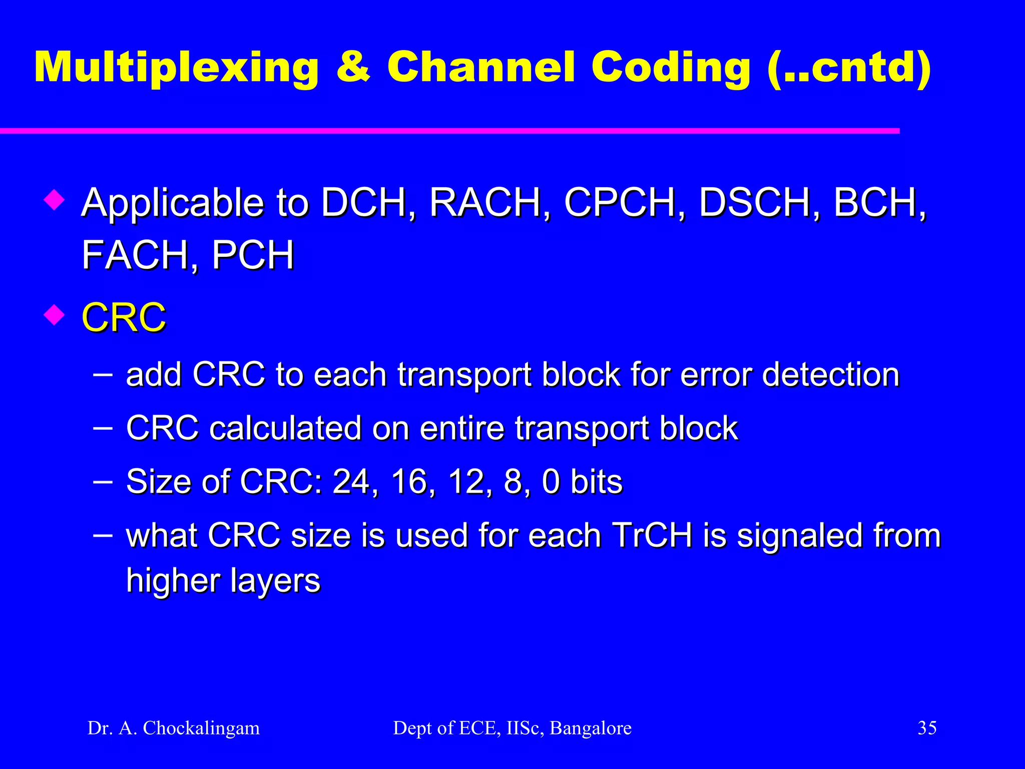
Dr. A. Chockalingam Dept of ECE, IISc, Bangalore Multiplexing & Channel Coding (..cntd) Applicable to DCH, RACH, CPCH, DSCH, BCH, FACH, PCH CRC add CRC to each transport block for error detection CRC calculated on entire transport block Size of CRC: 24, 16, 12, 8, 0 bits what CRC size is used for each TrCH is signaled from higher layers
36.
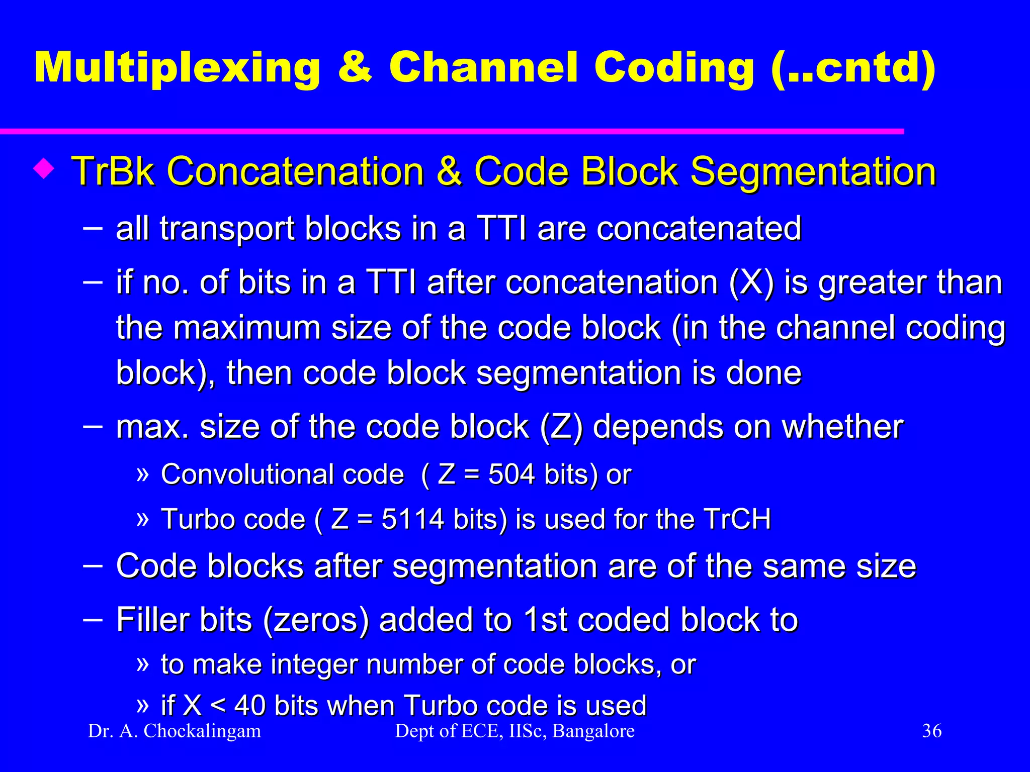
Dr. A. Chockalingam Dept of ECE, IISc, Bangalore Multiplexing & Channel Coding (..cntd) TrBk Concatenation & Code Block Segmentation all transport blocks in a TTI are concatenated if no. of bits in a TTI after concatenation (X) is greater than the maximum size of the code block (in the channel coding block), then code block segmentation is done max. size of the code block (Z) depends on whether Convolutional code ( Z = 504 bits) or Turbo code ( Z = 5114 bits) is used for the TrCH Code blocks after segmentation are of the same size Filler bits (zeros) added to 1st coded block to to make integer number of code blocks, or if X < 40 bits when Turbo code is used
37.
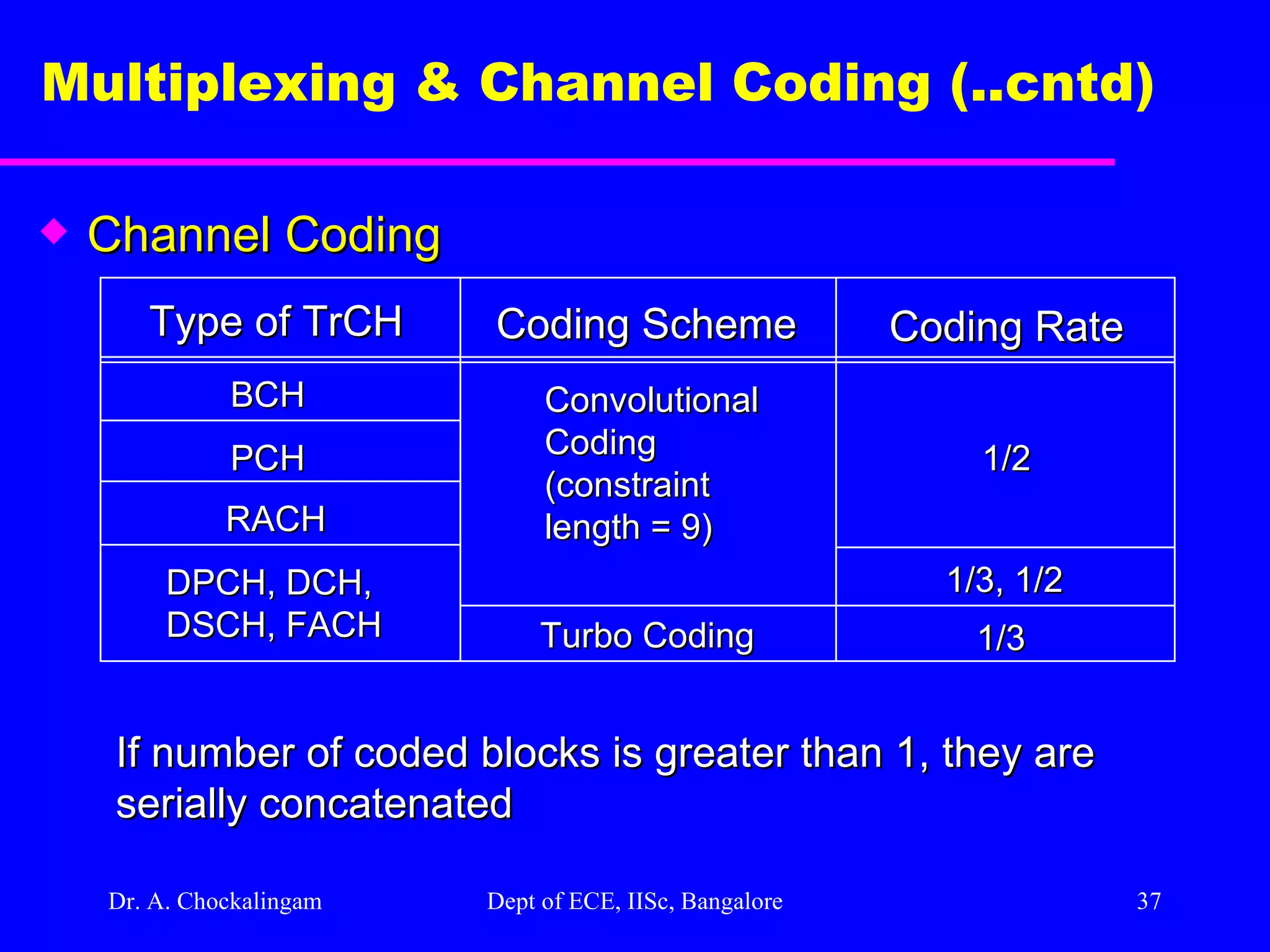
Dr. A. Chockalingam Dept of ECE, IISc, Bangalore Multiplexing & Channel Coding (..cntd) Channel Coding Coding Scheme Coding Rate Type of TrCH BCH PCH RACH DPCH, DCH, DSCH, FACH Convolutional Coding (constraint length = 9) Turbo Coding 1/3 1/3, 1/2 1/2 If number of coded blocks is greater than 1, they are serially concatenated
38.
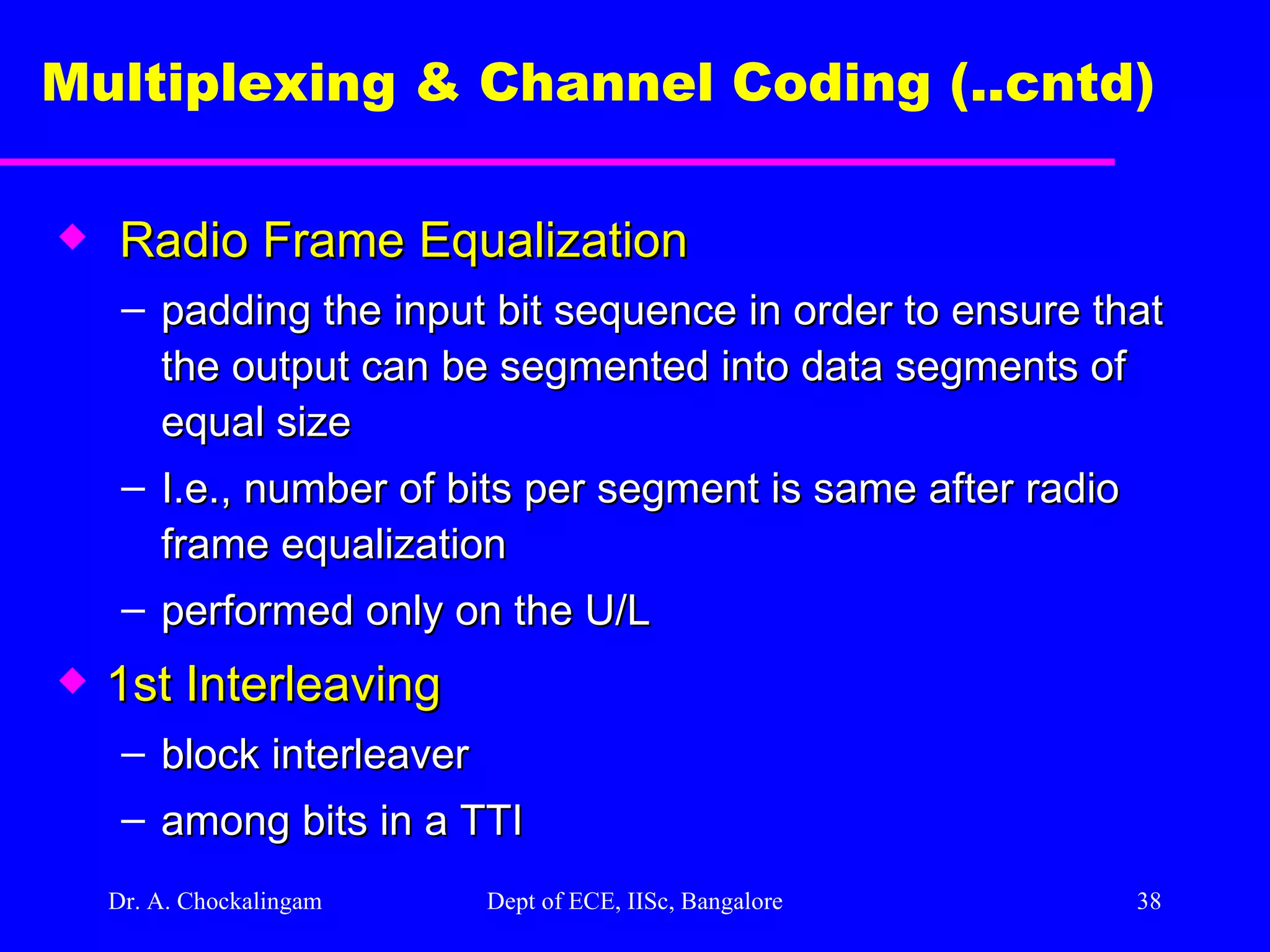
Dr. A. Chockalingam Dept of ECE, IISc, Bangalore Multiplexing & Channel Coding (..cntd) Radio Frame Equalization padding the input bit sequence in order to ensure that the output can be segmented into data segments of equal size I.e., number of bits per segment is same after radio frame equalization performed only on the U/L 1st Interleaving block interleaver among bits in a TTI
39.
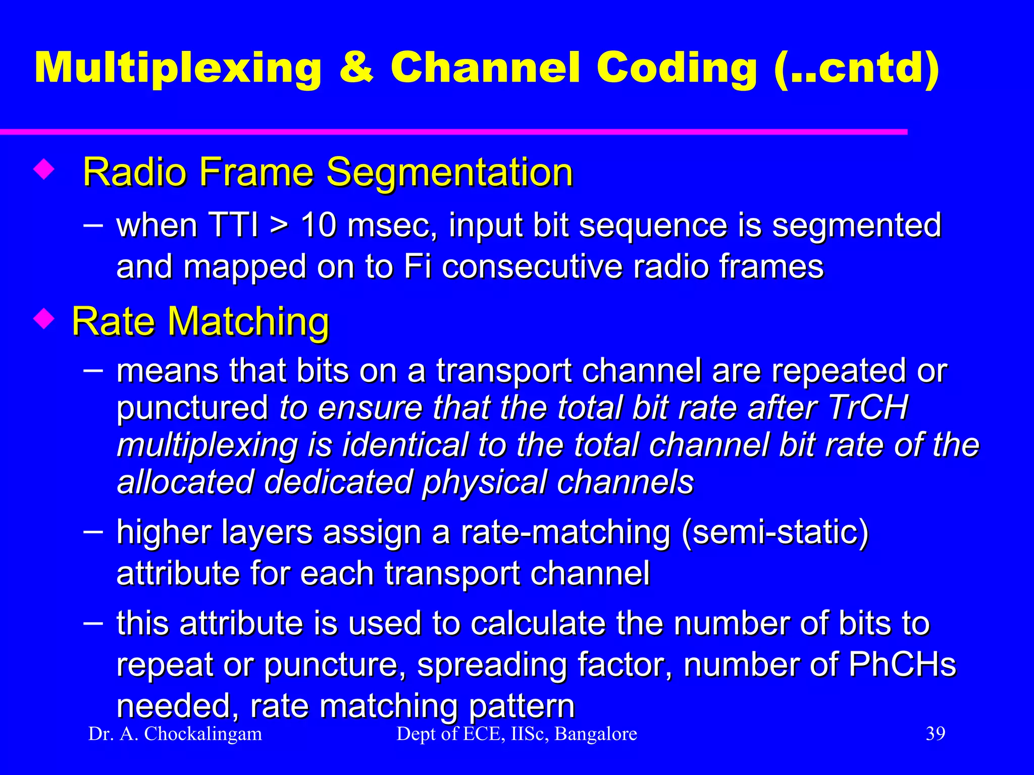
Dr. A. Chockalingam Dept of ECE, IISc, Bangalore Multiplexing & Channel Coding (..cntd) Radio Frame Segmentation when TTI > 10 msec, input bit sequence is segmented and mapped on to Fi consecutive radio frames Rate Matching means that bits on a transport channel are repeated or punctured to ensure that the total bit rate after TrCH multiplexing is identical to the total channel bit rate of the allocated dedicated physical channels higher layers assign a rate-matching (semi-static) attribute for each transport channel this attribute is used to calculate the number of bits to repeat or puncture, spreading factor, number of PhCHs needed, rate matching pattern
40.
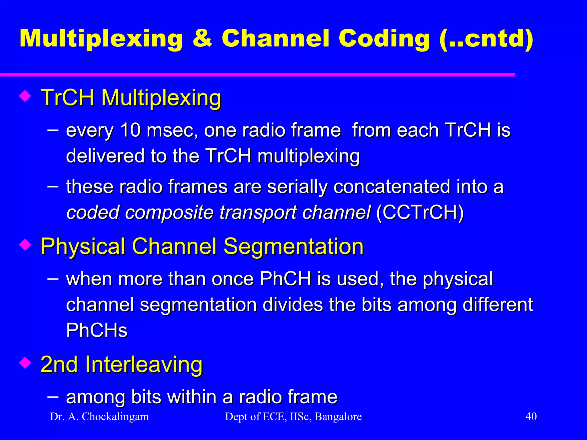
Dr. A. Chockalingam Dept of ECE, IISc, Bangalore Multiplexing & Channel Coding (..cntd) TrCH Multiplexing every 10 msec, one radio frame from each TrCH is delivered to the TrCH multiplexing these radio frames are serially concatenated into a coded composite transport channel (CCTrCH) Physical Channel Segmentation when more than once PhCH is used, the physical channel segmentation divides the bits among different PhCHs 2nd Interleaving among bits within a radio frame
41.
Dr. A. Chockalingam Dept of ECE, IISc, Bangalore Multiplexing & Channel Coding (..cntd) Insertion of Discontinuous Transmission (DTX) Indication Bits only on the D/L used to fill up the radio frame with bits insertion point depends on whether fixed positions (1st Insertion) or flexible positions (2nd Insertion) of the TrCHs in the radio frame are used During connection setup, NW decides if fixed or flexible position is used for each CCTrCH DTX Indication bits are not transmitted; they only tell when the Tx must be turned off
42.
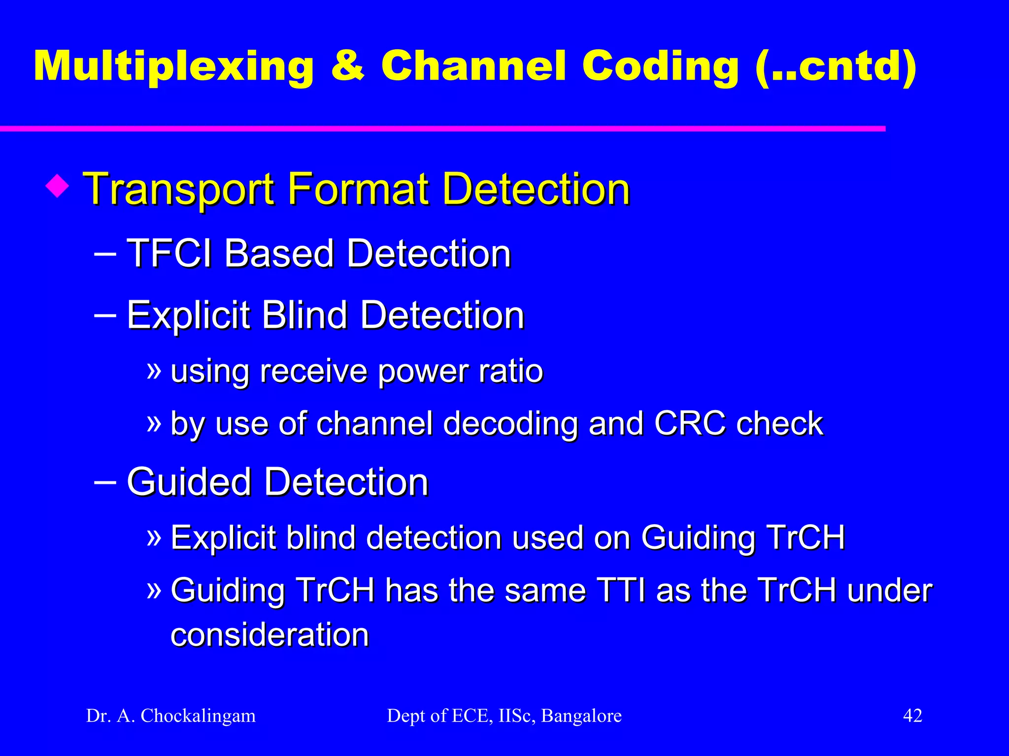
Dr. A. Chockalingam Dept of ECE, IISc, Bangalore Multiplexing & Channel Coding (..cntd) Transport Format Detection TFCI Based Detection Explicit Blind Detection using receive power ratio by use of channel decoding and CRC check Guided Detection Explicit blind detection used on Guiding TrCH Guiding TrCH has the same TTI as the TrCH under consideration
43.
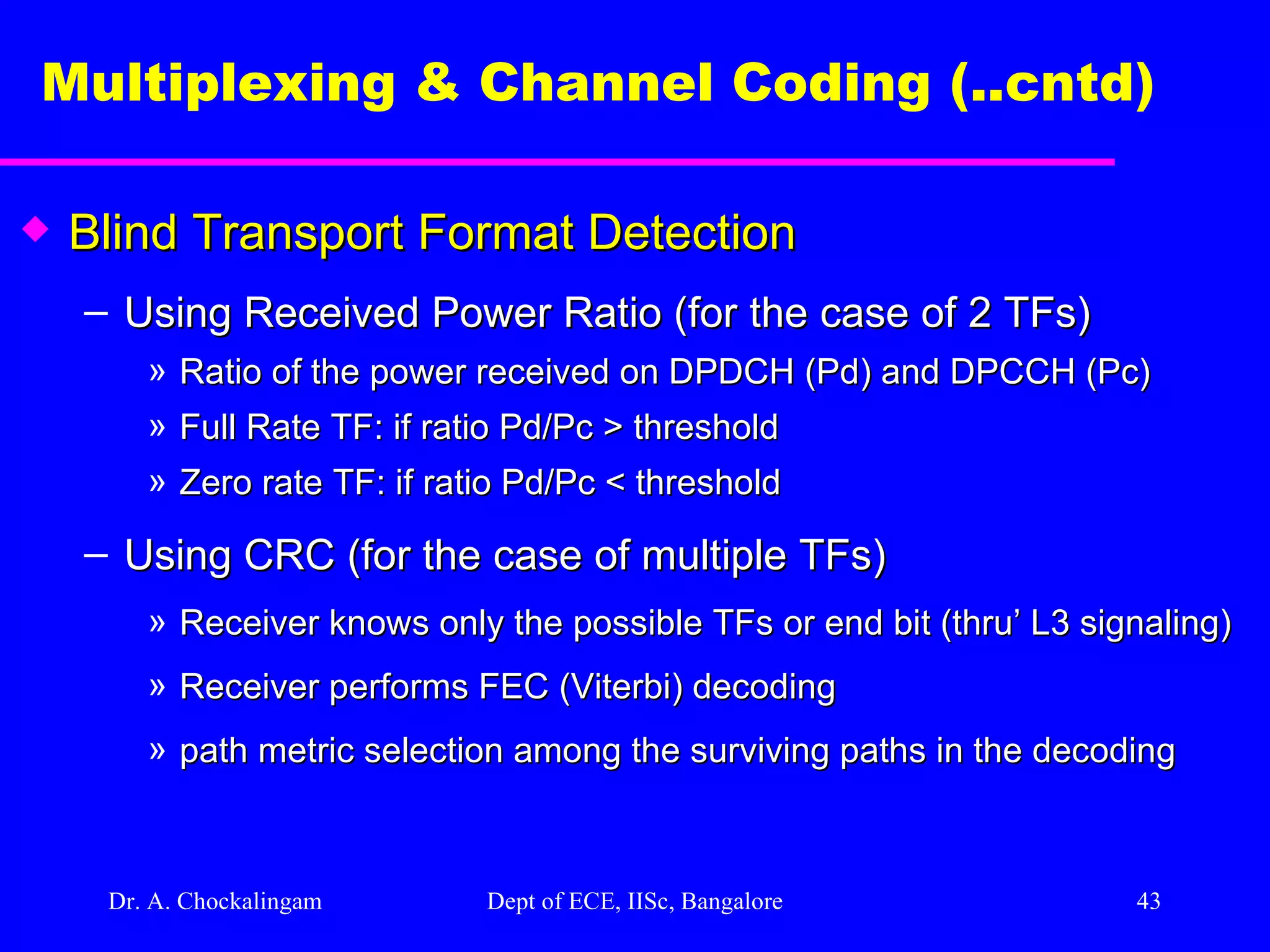
Dr. A. Chockalingam Dept of ECE, IISc, Bangalore Multiplexing & Channel Coding (..cntd) Blind Transport Format Detection Using Received Power Ratio (for the case of 2 TFs) Ratio of the power received on DPDCH (Pd) and DPCCH (Pc) Full Rate TF: if ratio Pd/Pc > threshold Zero rate TF: if ratio Pd/Pc < threshold Using CRC (for the case of multiple TFs) Receiver knows only the possible TFs or end bit (thru’ L3 signaling) Receiver performs FEC (Viterbi) decoding path metric selection among the surviving paths in the decoding
44.
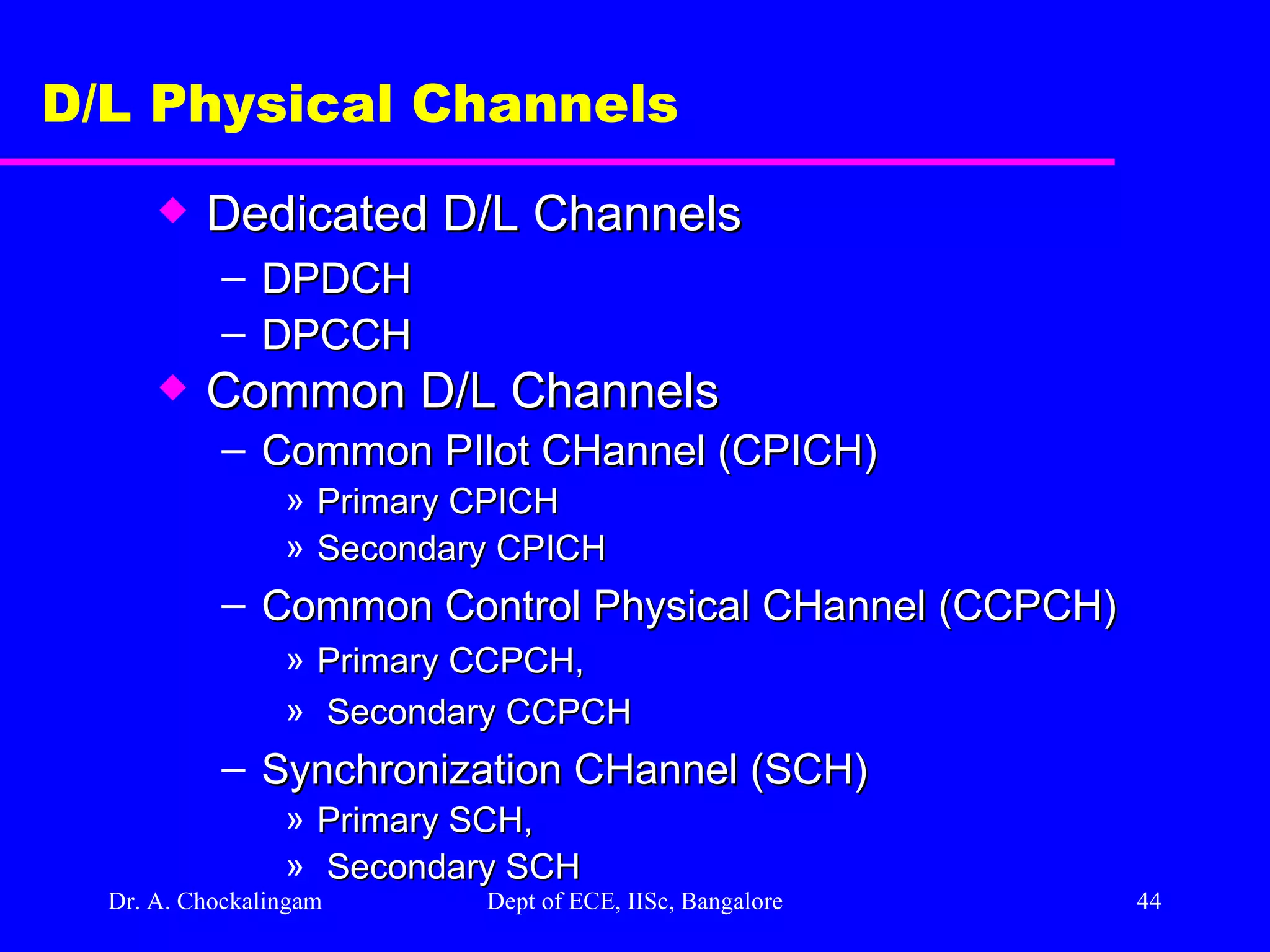
Dr. A. Chockalingam Dept of ECE, IISc, Bangalore D/L Physical Channels Dedicated D/L Channels DPDCH DPCCH Common D/L Channels Common PIlot CHannel (CPICH) Primary CPICH Secondary CPICH Common Control Physical CHannel (CCPCH) Primary CCPCH, Secondary CCPCH Synchronization CHannel (SCH) Primary SCH, Secondary SCH
45.
Dr. A. Chockalingam Dept of ECE, IISc, Bangalore Dedicated D/L Physical Channels Dedicated Physical CHannel (D/L DPCH) transmits dedicated data generated at L2 and above time-multiplexes with L1 control bits (Pilot, TPC, TFCI) D/L DPCH Time-multiplex of a D/L DPDCH and a D/L DPCCH
46.
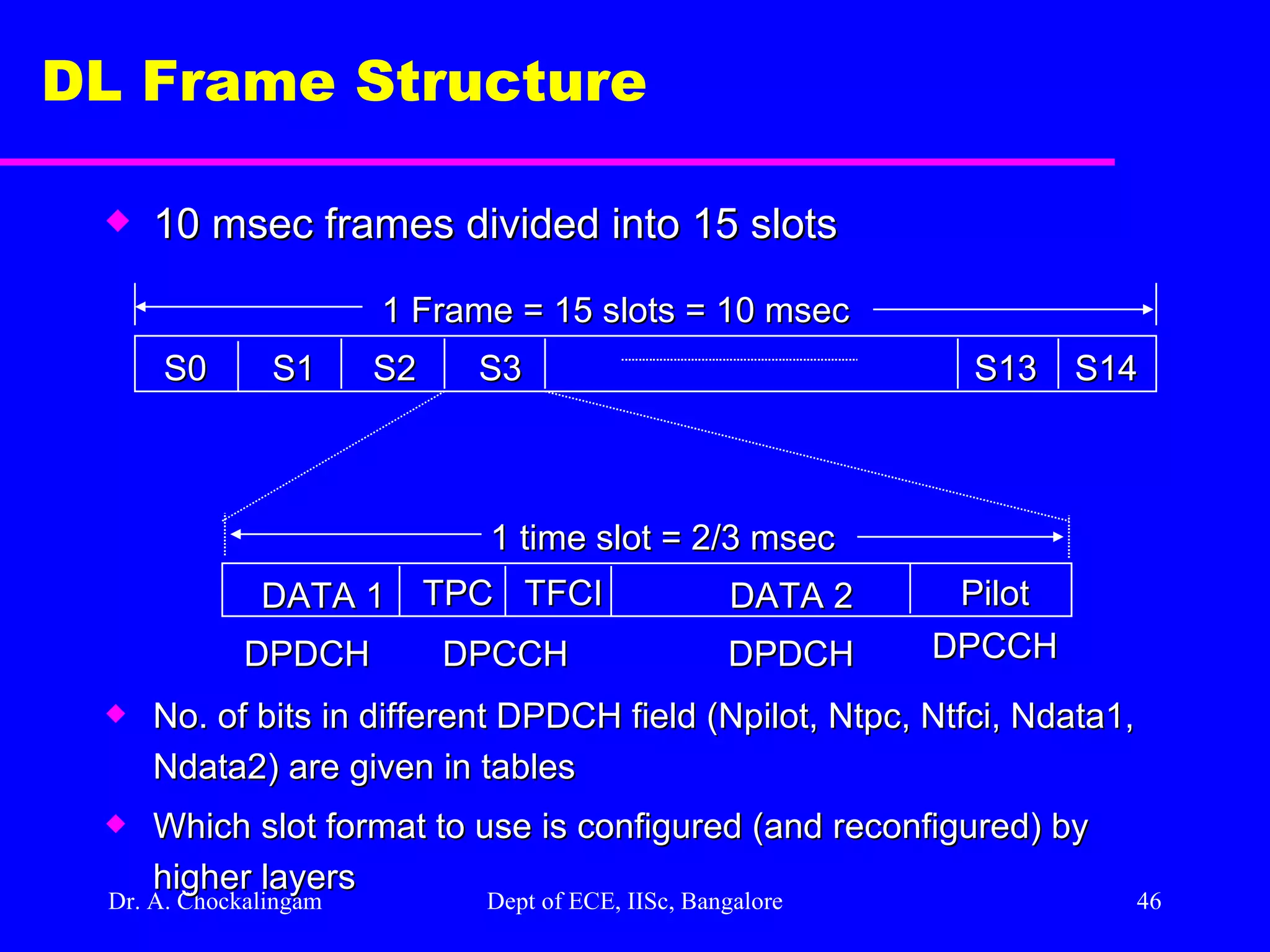
Dr. A. Chockalingam Dept of ECE, IISc, Bangalore DL Frame Structure S0 10 msec frames divided into 15 slots No. of bits in different DPDCH field (Npilot, Ntpc, Ntfci, Ndata1, Ndata2) are given in tables Which slot format to use is configured (and reconfigured) by higher layers S1 S2 S3 S13 S14 1 Frame = 15 slots = 10 msec DATA 1 1 time slot = 2/3 msec DPDCH Pilot DPCCH TFCI TPC DATA 2 DPDCH DPCCH
47.
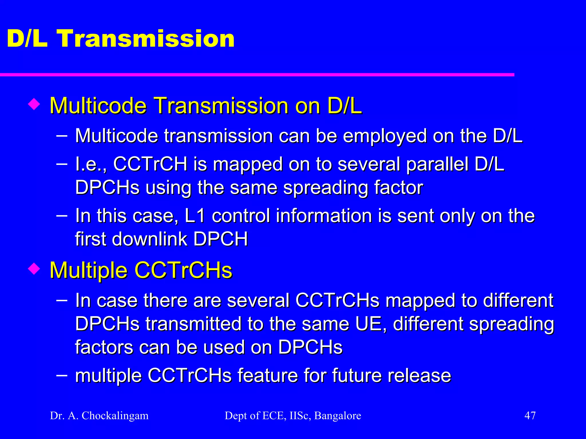
Dr. A. Chockalingam Dept of ECE, IISc, Bangalore D/L Transmission Multicode Transmission on D/L Multicode transmission can be employed on the D/L I.e., CCTrCH is mapped on to several parallel D/L DPCHs using the same spreading factor In this case, L1 control information is sent only on the first downlink DPCH Multiple CCTrCHs In case there are several CCTrCHs mapped to different DPCHs transmitted to the same UE, different spreading factors can be used on DPCHs multiple CCTrCHs feature for future release
48.
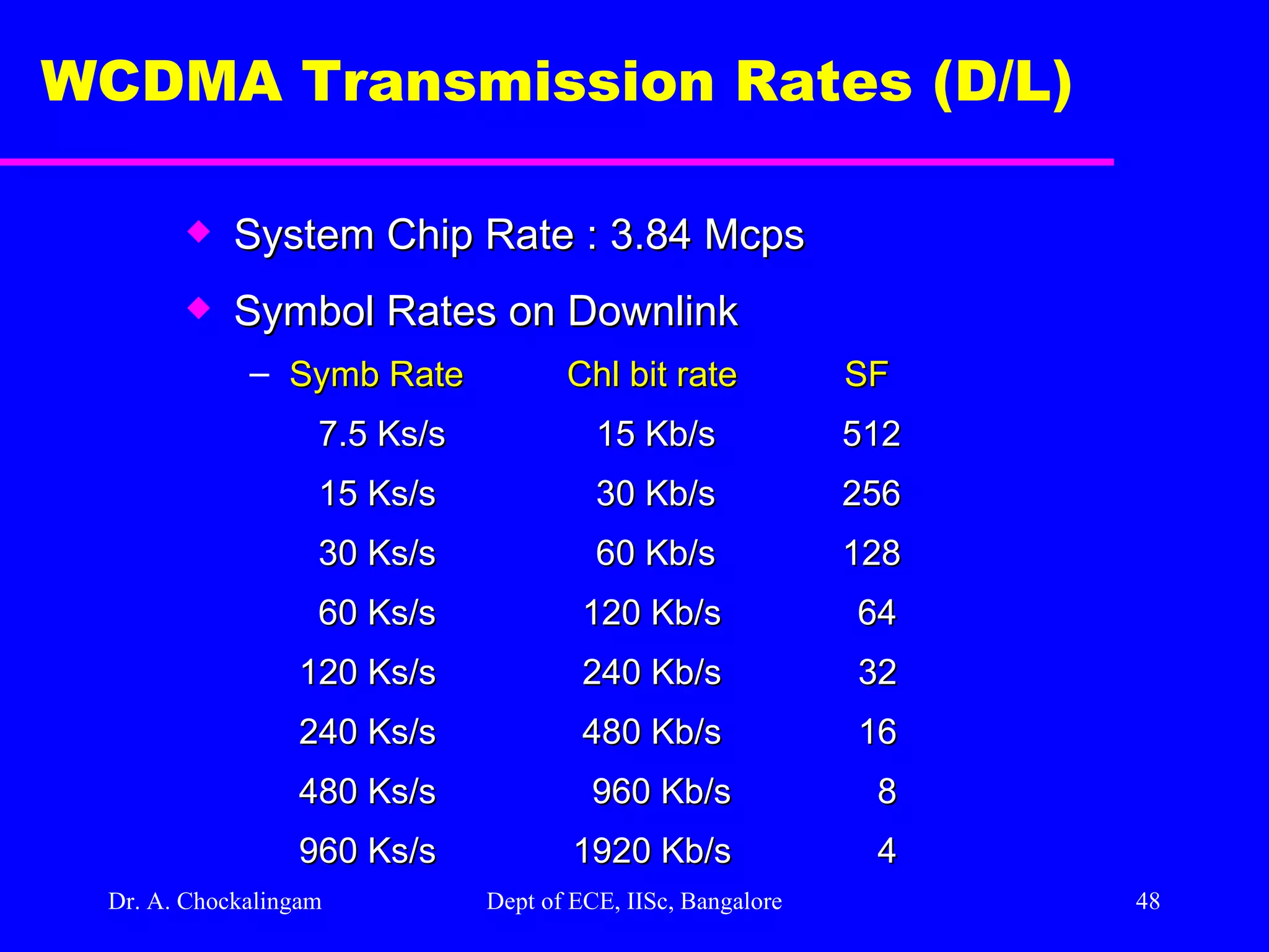
Dr. A. Chockalingam Dept of ECE, IISc, Bangalore WCDMA Transmission Rates (D/L) System Chip Rate : 3.84 Mcps Symbol Rates on Downlink Symb Rate Chl bit rate SF 7.5 Ks/s 15 Kb/s 512 15 Ks/s 30 Kb/s 256 30 Ks/s 60 Kb/s 128 60 Ks/s 120 Kb/s 64 120 Ks/s 240 Kb/s 32 240 Ks/s 480 Kb/s 16 480 Ks/s 960 Kb/s 8 960 Ks/s 1920 Kb/s 4
49.
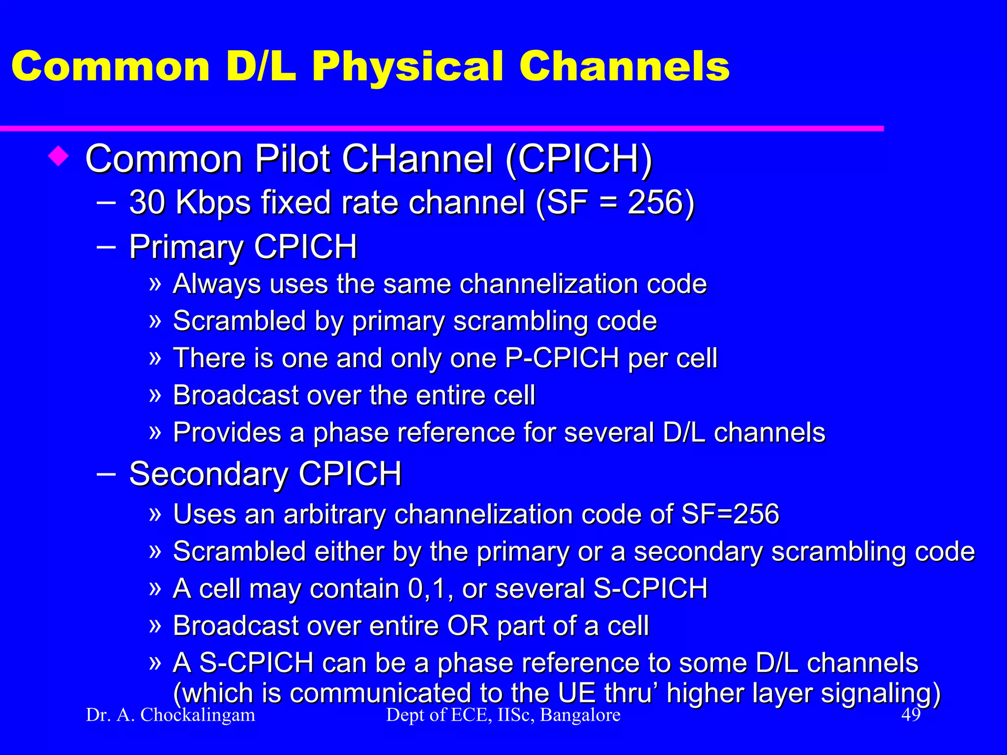
Dr. A. Chockalingam Dept of ECE, IISc, Bangalore Common D/L Physical Channels Common Pilot CHannel (CPICH) 30 Kbps fixed rate channel (SF = 256) Primary CPICH Always uses the same channelization code Scrambled by primary scrambling code There is one and only one P-CPICH per cell Broadcast over the entire cell Provides a phase reference for several D/L channels Secondary CPICH Uses an arbitrary channelization code of SF=256 Scrambled either by the primary or a secondary scrambling code A cell may contain 0,1, or several S-CPICH Broadcast over entire OR part of a cell A S-CPICH can be a phase reference to some D/L channels (which is communicated to the UE thru’ higher layer signaling)
50.
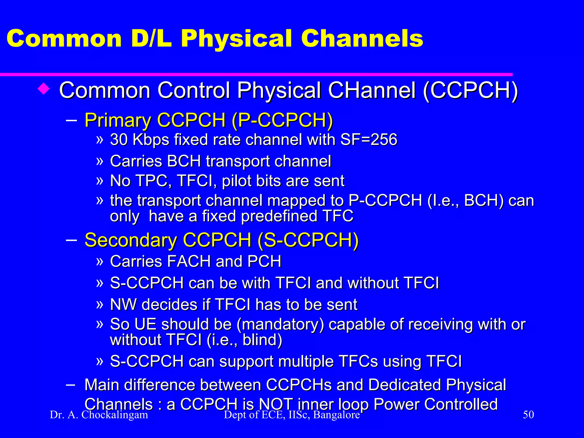
Dr. A. Chockalingam Dept of ECE, IISc, Bangalore Common D/L Physical Channels Common Control Physical CHannel (CCPCH) Primary CCPCH (P-CCPCH) 30 Kbps fixed rate channel with SF=256 Carries BCH transport channel No TPC, TFCI, pilot bits are sent the transport channel mapped to P-CCPCH (I.e., BCH) can only have a fixed predefined TFC Secondary CCPCH (S-CCPCH) Carries FACH and PCH S-CCPCH can be with TFCI and without TFCI NW decides if TFCI has to be sent So UE should be (mandatory) capable of receiving with or without TFCI (i.e., blind) S-CCPCH can support multiple TFCs using TFCI Main difference between CCPCHs and Dedicated Physical Channels : a CCPCH is NOT inner loop Power Controlled
51.
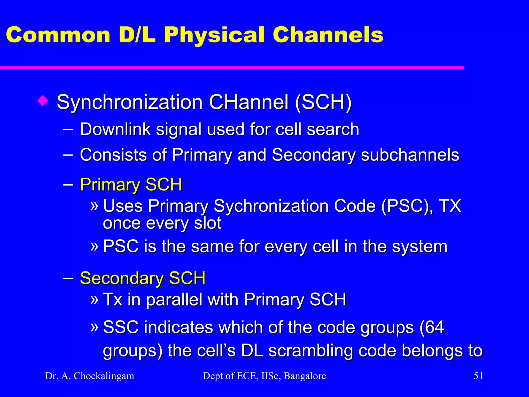
Dr. A. Chockalingam Dept of ECE, IISc, Bangalore Common D/L Physical Channels Synchronization CHannel (SCH) Downlink signal used for cell search Consists of Primary and Secondary subchannels Primary SCH Uses Primary Sychronization Code (PSC), TX once every slot PSC is the same for every cell in the system Secondary SCH Tx in parallel with Primary SCH SSC indicates which of the code groups (64 groups) the cell’s DL scrambling code belongs to
52.
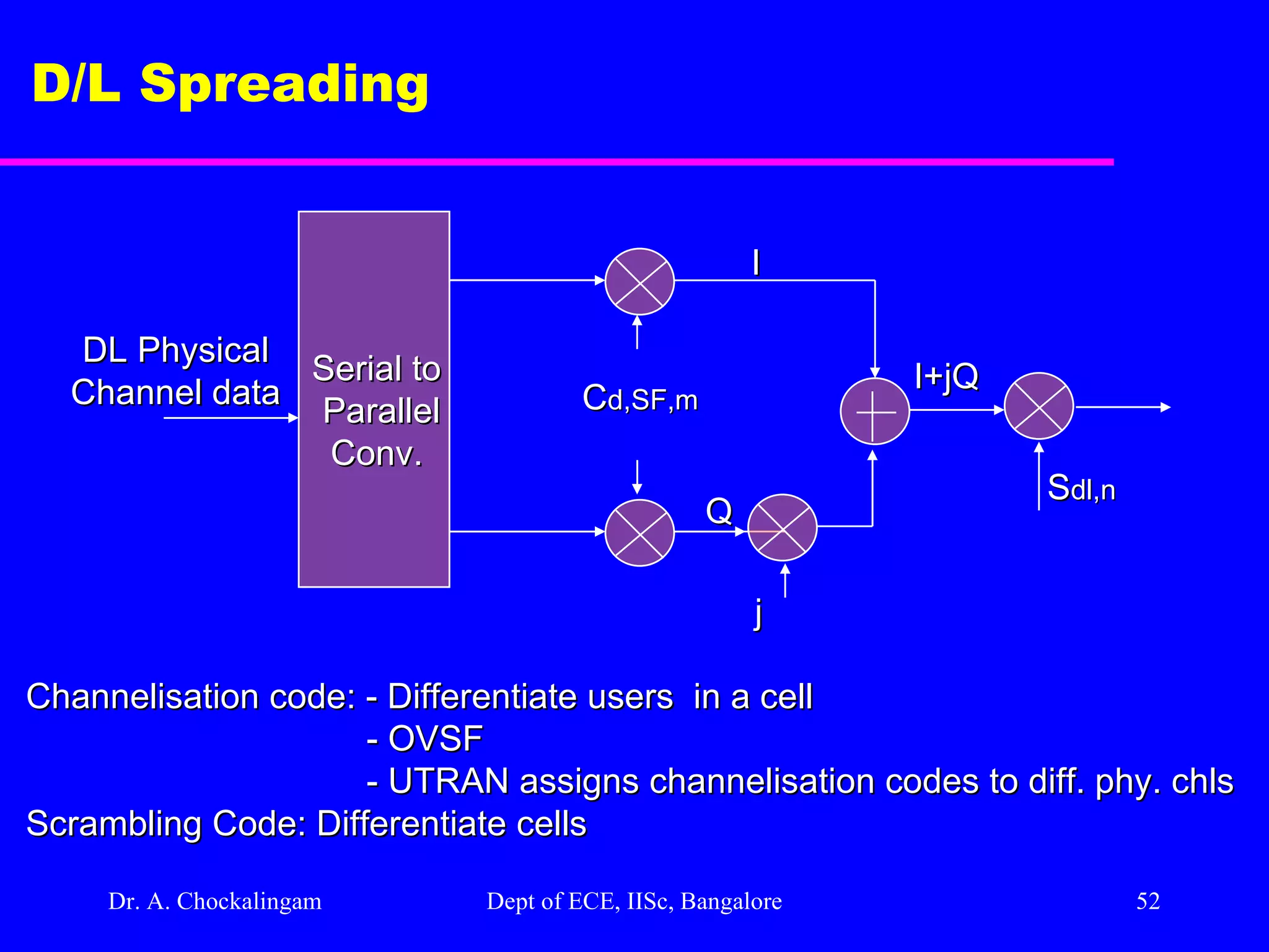
Dr. A. Chockalingam Dept of ECE, IISc, Bangalore D/L Spreading DL Physical Channel data C d,SF,m Serial to Parallel Conv. I Q I+jQ S dl,n j Channelisation code: - Differentiate users in a cell - OVSF - UTRAN assigns channelisation codes to diff. phy. chls Scrambling Code: Differentiate cells
53.
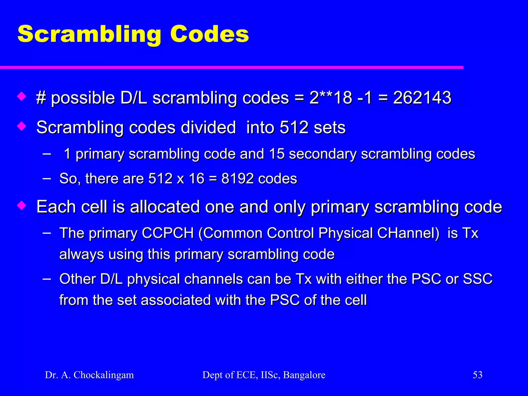
Dr. A. Chockalingam Dept of ECE, IISc, Bangalore Scrambling Codes # possible D/L scrambling codes = 2**18 -1 = 262143 Scrambling codes divided into 512 sets 1 primary scrambling code and 15 secondary scrambling codes So, there are 512 x 16 = 8192 codes Each cell is allocated one and only primary scrambling code The primary CCPCH (Common Control Physical CHannel) is Tx always using this primary scrambling code Other D/L physical channels can be Tx with either the PSC or SSC from the set associated with the PSC of the cell
54.
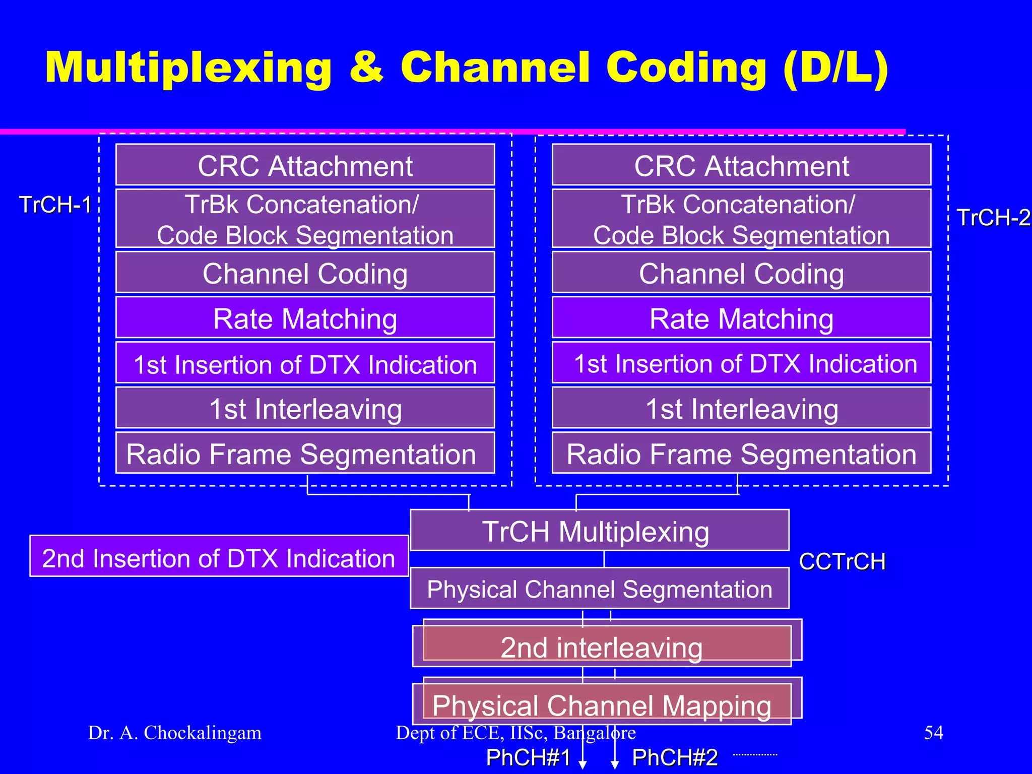
Dr. A. Chockalingam Dept of ECE, IISc, Bangalore Multiplexing & Channel Coding (D/L) CRC Attachment TrBk Concatenation/ Code Block Segmentation Channel Coding Rate Matching 1st Insertion of DTX Indication 1st Interleaving Radio Frame Segmentation CCTrCH CRC Attachment TrBk Concatenation/ Code Block Segmentation Channel Coding Rate Matching 1st Insertion of DTX Indication 1st Interleaving Radio Frame Segmentation TrCH-2 TrCH Multiplexing Physical Channel Segmentation 2nd interleaving TrCH-1 Physical Channel Mapping PhCH#2 PhCH#1 2nd Insertion of DTX Indication
55.
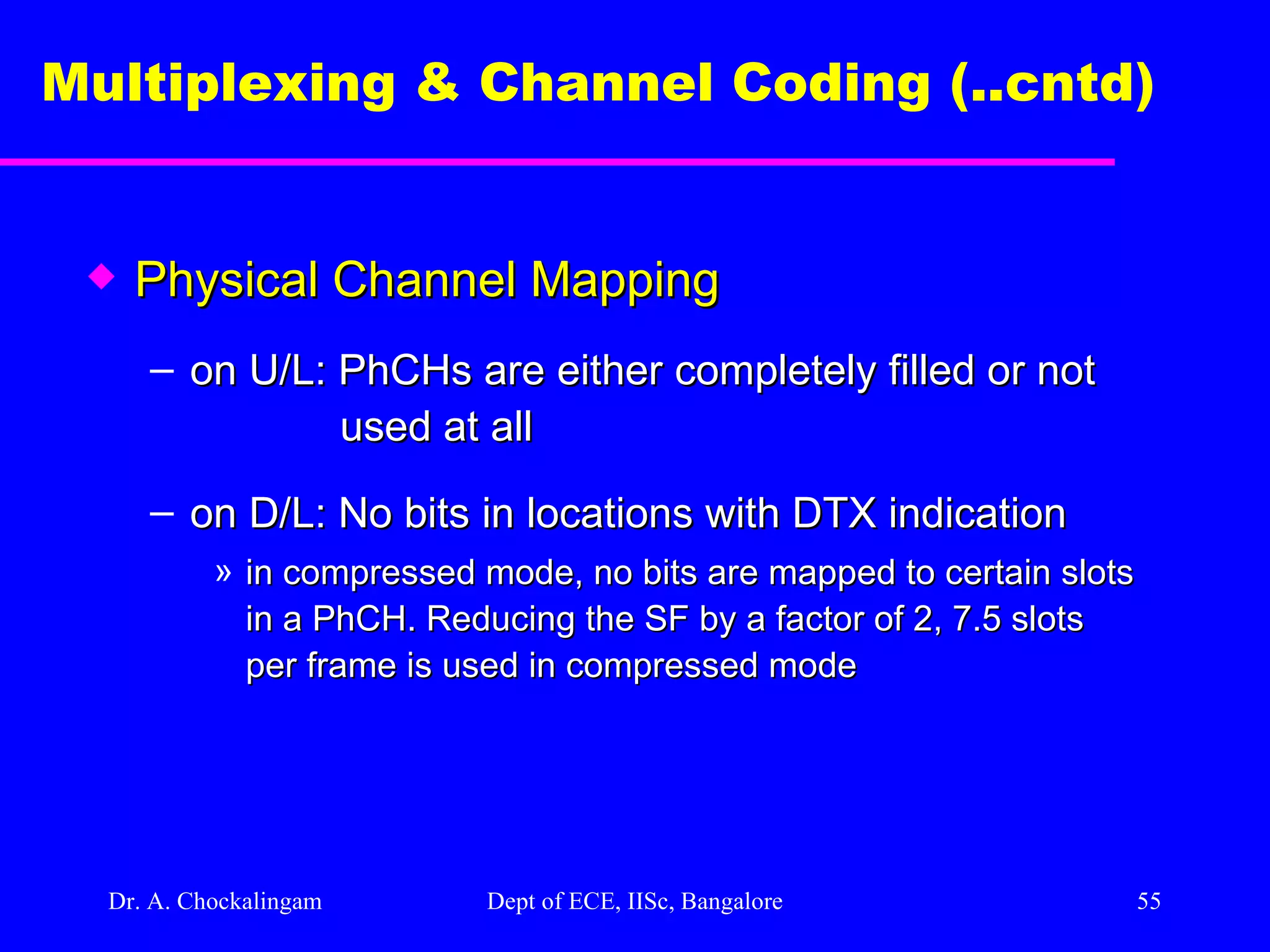
Dr. A. Chockalingam Dept of ECE, IISc, Bangalore Multiplexing & Channel Coding (..cntd) Physical Channel Mapping on U/L: PhCHs are either completely filled or not used at all on D/L: No bits in locations with DTX indication in compressed mode, no bits are mapped to certain slots in a PhCH. Reducing the SF by a factor of 2, 7.5 slots per frame is used in compressed mode
56.
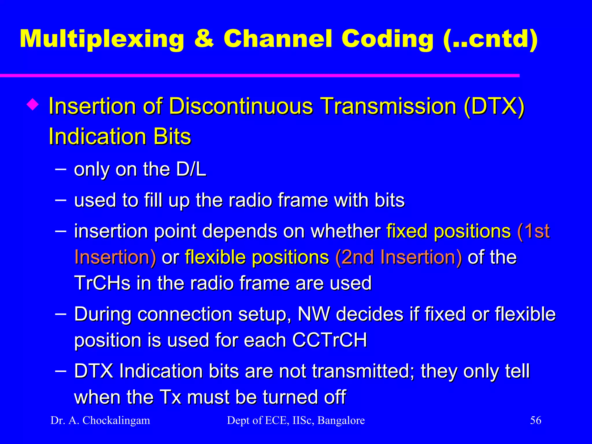
Dr. A. Chockalingam Dept of ECE, IISc, Bangalore Multiplexing & Channel Coding (..cntd) Insertion of Discontinuous Transmission (DTX) Indication Bits only on the D/L used to fill up the radio frame with bits insertion point depends on whether fixed positions (1st Insertion) or flexible positions (2nd Insertion) of the TrCHs in the radio frame are used During connection setup, NW decides if fixed or flexible position is used for each CCTrCH DTX Indication bits are not transmitted; they only tell when the Tx must be turned off
57.
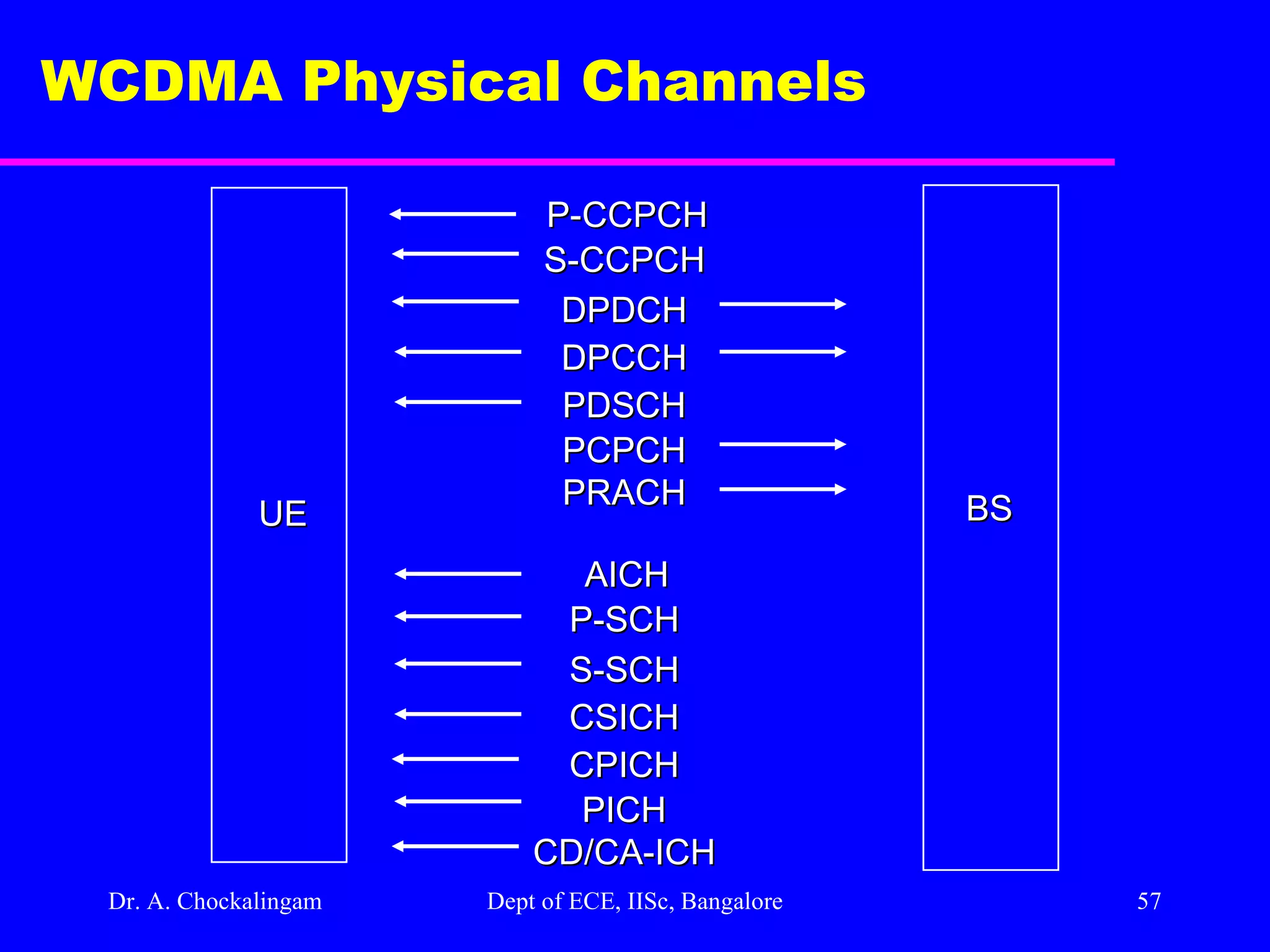
Dr. A. Chockalingam Dept of ECE, IISc, Bangalore WCDMA Physical Channels P-CCPCH S-CCPCH DPDCH DPCCH PDSCH PCPCH PRACH BS UE AICH P-SCH S-SCH CSICH CPICH PICH CD/CA-ICH
58.
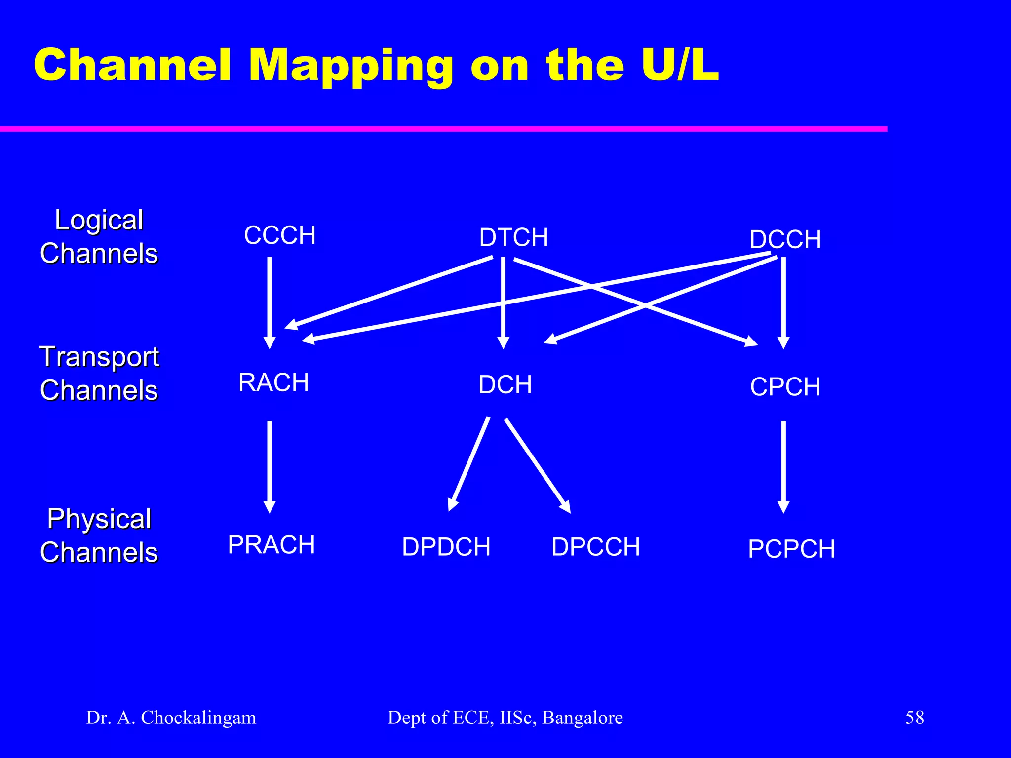
Dr. A. Chockalingam Dept of ECE, IISc, Bangalore Channel Mapping on the U/L CCCH DTCH DCCH RACH DCH CPCH PRACH DPDCH DPCCH PCPCH Logical Channels Transport Channels Physical Channels
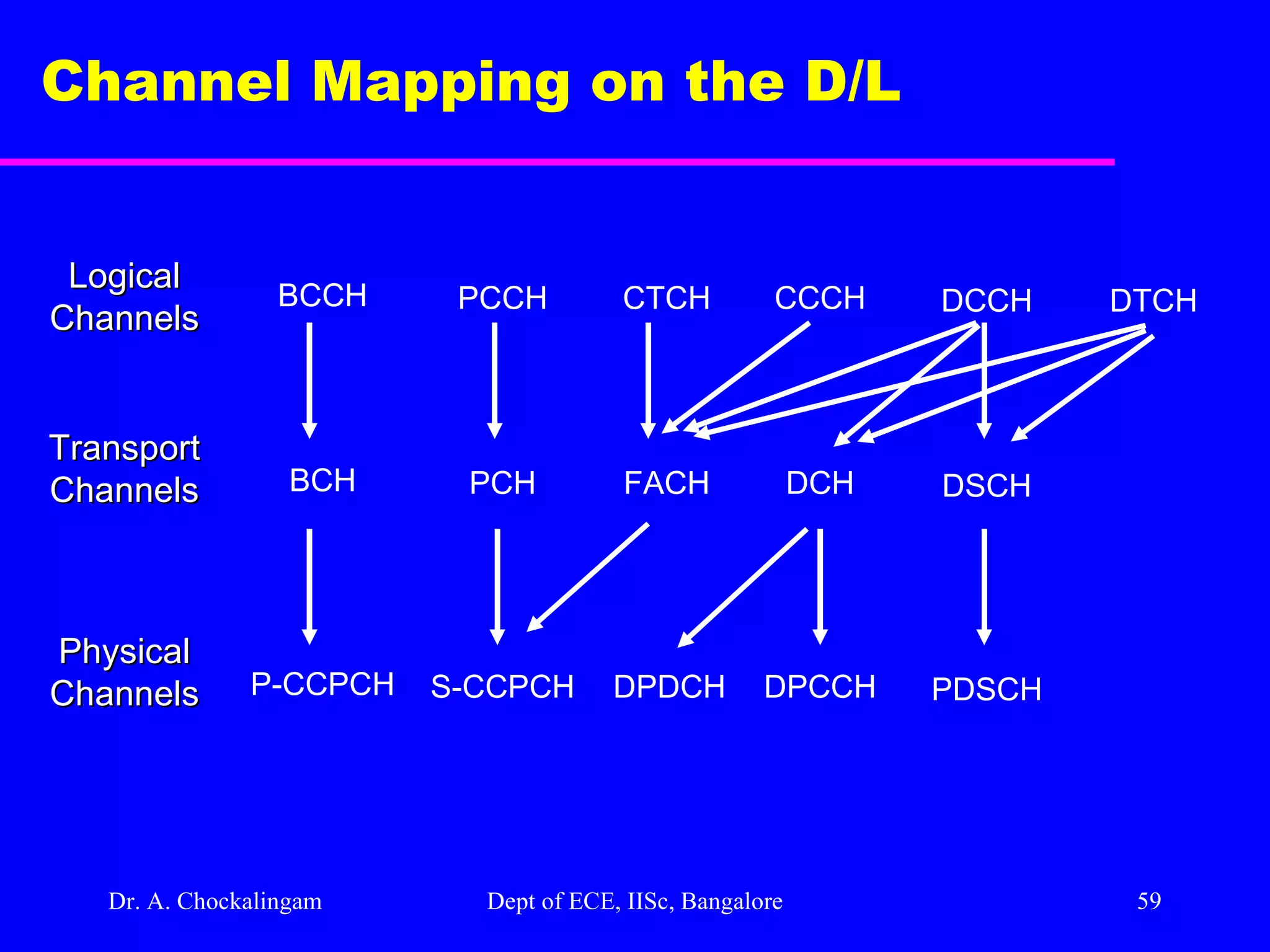
59.
Dr. A. Chockalingam Dept of ECE, IISc, Bangalore Channel Mapping on the D/L BCCH PCCH CTCH CCCH DCCH DTCH BCH PCH FACH DCH DSCH P-CCPCH S-CCPCH DPDCH DPCCH PDSCH Logical Channels Transport Channels Physical Channels
![WCDMA Physical Layer Design A. Chockalingam Assistant Professor Indian Institute of Science, Bangalore-12 [email_address] http://ece.iisc.ernet.in/~achockal](https://image.slidesharecdn.com/wcdmaphysicallayer-111120031701-phpapp02/75/Wcdma-physical-layer-1-2048.jpg)