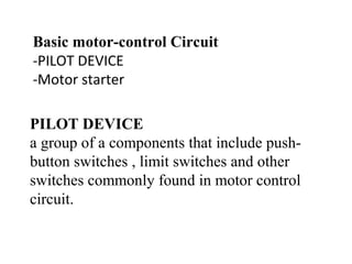
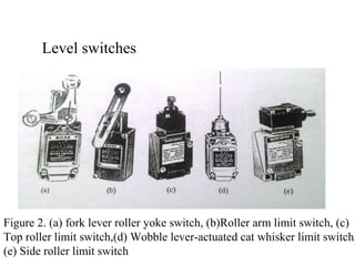
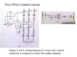
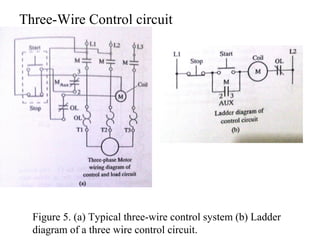
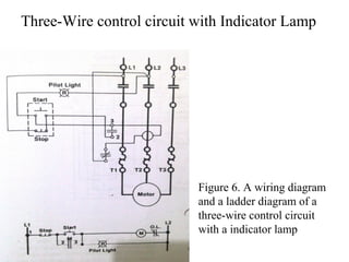
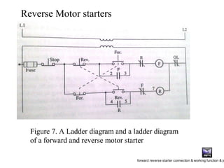
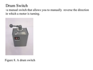
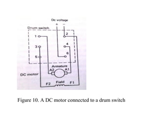
Al barra Harahap(20215036)
Myo Myint shein(20215701)
MOTOR CONTROL DEVICES AND
CIRCUIT
Group-5
Basic motor-control Circuit
-PILOT DEVICE
-Motor starter
PILOT DEVICE
a group of a components that include push-
button switches , limit switches and other
switches commonly found in motor control
circuit.
Firgure 1. Push button switches
Push button switches
Figure 2. (a) fork lever roller yoke switch, (b)Roller arm limit switch, (c)
Top roller limit switch,(d) Wobble lever-actuated cat whisker limit switch,
(e) Side roller limit switch
Level switches
Control Circuit
-the control compnents ,which are the switches and coils that control the
load.
Load Circuit
- the load components such as motor that cause the system to perform
some type of action.
Figure 3. A Ladder
diagram of a control
circuit and a load circuit
Two-Wire Control circuit
Figure 4. (a) A wiring diagram of a two-wire control
circuit for a compressor motor (b) Ladder diagram
Three-Wire Control circuit
Figure 5. (a) Typical three-wire control system (b) Ladder
diagram of a three wire control circuit.
Three-Wire control circuit with Indicator Lamp
Figure 6. A wiring diagram
and a ladder diagram of a
three-wire control circuit
with a indicator lamp
Reverse Motor starters
Figure 7. A Ladder diagram and a ladder diagram
of a forward and reverse motor starter
forward reverse starter connection & working function & jo
Drum Switch
-a manual switch that allows you to manually reverse the direction
in which a motor is turning.
Figure 8. A drum switch
(a) (b) (c)
Figure 9. (a) Contacts of a drum switch when it is switched to the reverse
position. (b) Contacts of a drum switch when it is switched to the off
position. (c) Contacts of a drum switch when it is switched to the
forward position.
Figure 9. A single-phase AC motor connected to a drum switch and
A three-phase AC motor connected to a drum switch
Figure 10. A DC motor connected to a drum switch
Other Types of Pilot Devices
-Flow switch
(a device that monitors the flow of air, steam or liquid.
It sends a "trip signal" to a different device in the system, such as
a pump.)
-Level switch
(On-off switch that senses high or low liquid levels. A
displacer is used as the sensor and is located in an external cage
that mounts to the outside of a vessel.)
-Pressure switch
(a form of switch that closes an electrical contact when a
certain set pressure has been reached on its input.)
(a) (c)(b)
Figure 10. (a) Flow switch, (b) level switch and (c) Pressure switch
Terima kasih Banyak

Motor control

  • 1.
    Al barra Harahap(20215036) MyoMyint shein(20215701) MOTOR CONTROL DEVICES AND CIRCUIT Group-5
  • 2.
    Basic motor-control Circuit -PILOTDEVICE -Motor starter PILOT DEVICE a group of a components that include push- button switches , limit switches and other switches commonly found in motor control circuit.
  • 3.
    Firgure 1. Pushbutton switches Push button switches
  • 4.
    Figure 2. (a)fork lever roller yoke switch, (b)Roller arm limit switch, (c) Top roller limit switch,(d) Wobble lever-actuated cat whisker limit switch, (e) Side roller limit switch Level switches
  • 5.
    Control Circuit -the controlcompnents ,which are the switches and coils that control the load. Load Circuit - the load components such as motor that cause the system to perform some type of action. Figure 3. A Ladder diagram of a control circuit and a load circuit
  • 6.
    Two-Wire Control circuit Figure4. (a) A wiring diagram of a two-wire control circuit for a compressor motor (b) Ladder diagram
  • 7.
    Three-Wire Control circuit Figure5. (a) Typical three-wire control system (b) Ladder diagram of a three wire control circuit.
  • 8.
    Three-Wire control circuitwith Indicator Lamp Figure 6. A wiring diagram and a ladder diagram of a three-wire control circuit with a indicator lamp
  • 9.
    Reverse Motor starters Figure7. A Ladder diagram and a ladder diagram of a forward and reverse motor starter forward reverse starter connection & working function & jo
  • 10.
    Drum Switch -a manualswitch that allows you to manually reverse the direction in which a motor is turning. Figure 8. A drum switch
  • 11.
    (a) (b) (c) Figure9. (a) Contacts of a drum switch when it is switched to the reverse position. (b) Contacts of a drum switch when it is switched to the off position. (c) Contacts of a drum switch when it is switched to the forward position.
  • 12.
    Figure 9. Asingle-phase AC motor connected to a drum switch and A three-phase AC motor connected to a drum switch
  • 13.
    Figure 10. ADC motor connected to a drum switch
  • 14.
    Other Types ofPilot Devices -Flow switch (a device that monitors the flow of air, steam or liquid. It sends a "trip signal" to a different device in the system, such as a pump.) -Level switch (On-off switch that senses high or low liquid levels. A displacer is used as the sensor and is located in an external cage that mounts to the outside of a vessel.) -Pressure switch (a form of switch that closes an electrical contact when a certain set pressure has been reached on its input.)
  • 15.
    (a) (c)(b) Figure 10.(a) Flow switch, (b) level switch and (c) Pressure switch
  • 16.