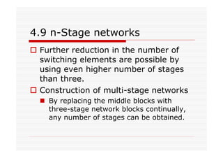
Download as PDF, PPTX


![Blocking probability analysis
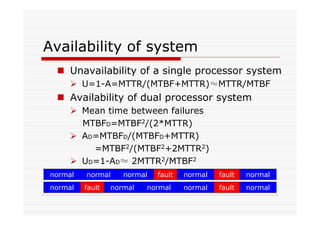
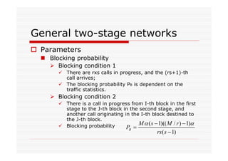
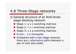
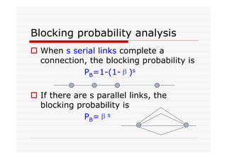
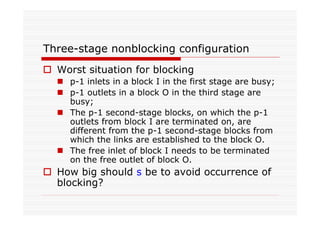
The blocking probability of NxN three-stage
network
If α denotes the probability that a inlet at the
first stage is busy, then β=αp/s = α/k, where k=s/p
There are s parallel paths
Each path consists of two serial links
Blocking probability of each path is
1-(1-β)2=1-(1- α/k)2
Total Blocking probability is
PB=[1-(1-β)2]s=[1-(1- α/k)2]s
What is
the
meaning
of k?](https://image.slidesharecdn.com/module3part1-150525051420-lva1-app6891/85/Module3-part1-96-320.jpg)

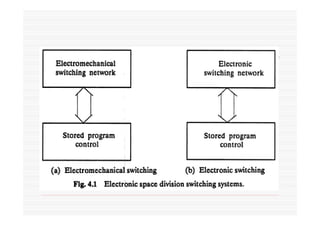
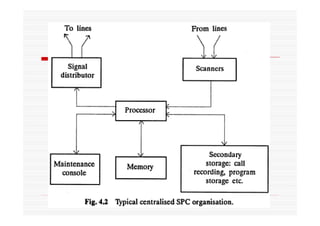
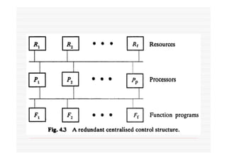
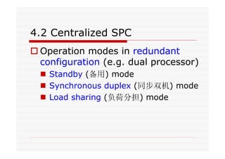
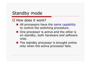
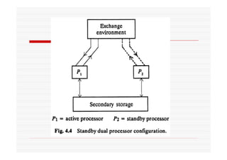
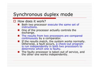
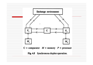
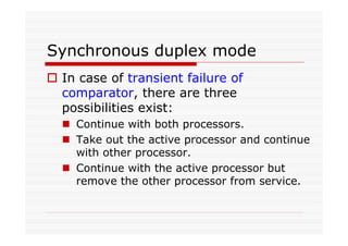
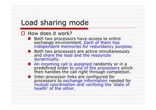
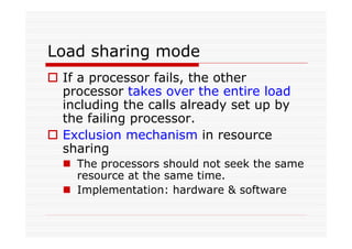
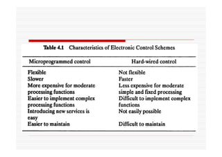
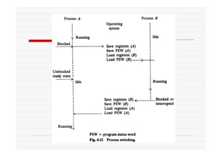
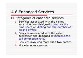
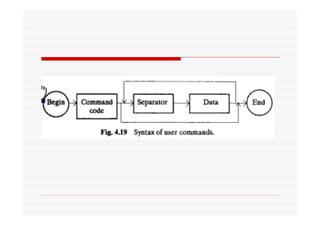
Chapter 4 discusses Electronic Space Division Switching, focusing on stored program control (SPC) systems and their applications in centralized and distributed switching networks. Key features and operations of SPC, including various control modes such as standby, synchronous duplex, and load sharing, are outlined, as well as the architectural and software considerations necessary for efficient operation. The chapter also covers enhanced services and the design principles of two-stage networks, emphasizing their advantages in telecommunications.