Downloaded 299 times

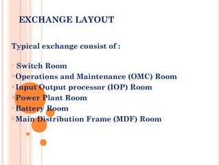
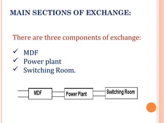
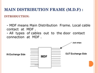
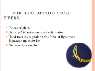
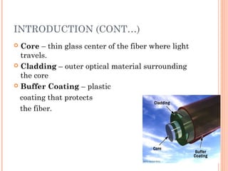

BSNL Summer Training document provides an overview of BSNL and telecommunications systems. It discusses the exchange, which houses switching equipment to interconnect telephones. The exchange includes a switch room, operations room, and main distribution frame (MDF) room. The MDF is the primary location for removing faults and disconnecting telephone numbers. The document also briefly outlines optical fiber technology and its advantages for data transmission.


