Downloaded 12 times
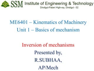
![[a] Pendulum pump:
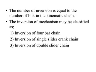
• When the sliding pair is
fixed, the mechanism is
known as pendulum pump.
• As the figure, link 2 (crank)
rotates, link 3 (connecting
rod) oscillates about a pin C
and the piston attached to
piston rod (link 1)
reciprocates in the cylinder.](https://image.slidesharecdn.com/inversions-230128090758-b7c9903c/85/Inversions-ppt-8-320.jpg)
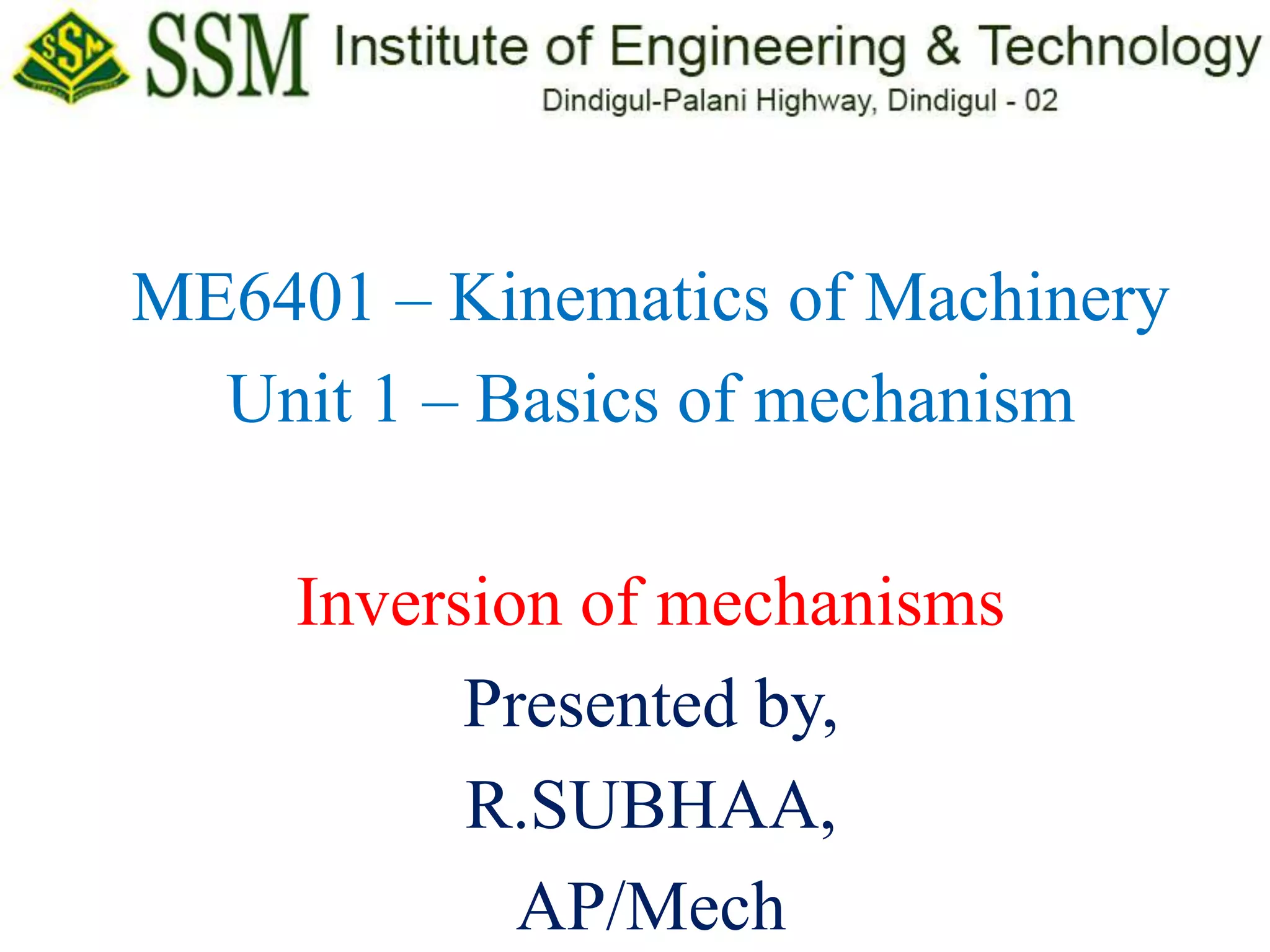
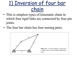
![[b] Oscillating cylinder engine:
• In this mechanism link 3 is fixed. The link 2
rotates, the link 1 (piston rod) reciprocate and
the link 4 (cylinder) oscillate about a pin A.](https://image.slidesharecdn.com/inversions-230128090758-b7c9903c/85/Inversions-ppt-9-320.jpg)
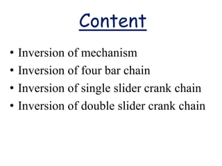
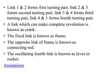
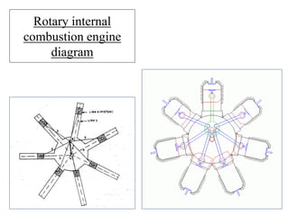
![[c] Rotary internal combustion engine:
• This mechanism is used in multi cylinder
engine.
• It consists of several cylinders in one plane and
all revolve about fixed center O, as shown
figure.
• The crank (link 2) is fixed.
• When the connecting rod (link 4) rotates, the
piston (link 3) reciprocates inside the cylinder
forming link 1.](https://image.slidesharecdn.com/inversions-230128090758-b7c9903c/85/Inversions-ppt-10-320.jpg)
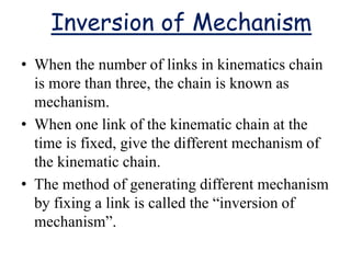
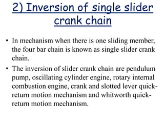
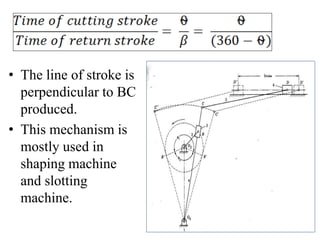
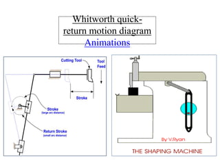
![[d] Crank and slotted lever quick-
return motion mechanism:
• In this mechanism, link 1 is slider which slide in
slotted lever.
• The slotted lever is link 4. link 3 is fixed where
the center of crank attached.
• Link 2 is crank which rotates in clockwise
direction.
• Link 4 is the arm which oscillates about point C.
• A short link DE transmits the motion with
reciprocates with the tool along line of stroke.](https://image.slidesharecdn.com/inversions-230128090758-b7c9903c/85/Inversions-ppt-12-320.jpg)
![3) Inversion of Double
slider crank chain
• There are four type of inversion of double
slider crank chain mechanism as:
[a] Elliptical trammel
[b] Scotch yoke mechanism
[c] Oldham’s coupling
[d] Donkey Pump](https://image.slidesharecdn.com/inversions-230128090758-b7c9903c/85/Inversions-ppt-15-320.jpg)
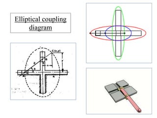
![[a] Elliptical Coupling:
• In this mechanism two slots are cut at right
angles in a plane which is fixed.
• Two blocks slide in these two slots.
• Two sliding blocks form two links, which are of
sliding type.
• Two sliding blocks are connected by one link.
• Point on this link at anywhere generate ellipse,
when any ne blocks slides in its slot.](https://image.slidesharecdn.com/inversions-230128090758-b7c9903c/85/Inversions-ppt-16-320.jpg)
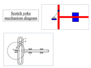
![[b] Scotch yoke mechanism:
• This mechanism converts rotary motion to
reciprocating motion (simple harmonic motion).
• It is used in vibration exciter to produce vibration
of desired frequency.
• This Chain has two revolute pairs and two
prismatic pairs.
• The first inversion is with a link with revolute
pair and prismatic pair is fixed.](https://image.slidesharecdn.com/inversions-230128090758-b7c9903c/85/Inversions-ppt-18-320.jpg)
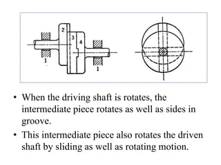
![[c] Oldham’s Coupling:
• When the distance between two shaft axes is
small, motion is transmitted by oldham’s
coupling.
• At the end of both the shafts there is flanges.
• This flange forms links 2 and 4.
• Both this links forms a turning pair with link 3.
• There is a diametrical slot on both the flange.
• An intermediate piece have a diametrical outside
tongues at right angle on both sides.](https://image.slidesharecdn.com/inversions-230128090758-b7c9903c/85/Inversions-ppt-20-320.jpg)


This document discusses the inversion of mechanisms. It begins by defining inversion of mechanisms as generating different mechanisms by fixing one link in a kinematic chain. It then discusses three types of inversions: 1) inversion of a four bar chain, which includes inverting links in a chain with four rigid links connected by four pin joints, 2) inversion of a single slider crank chain, which includes mechanisms like a pendulum pump or oscillating cylinder engine, and 3) inversion of a double slider crank chain, which includes mechanisms like an elliptical trammel or scotch yoke mechanism. Diagrams and examples are provided for each type of inversion.


![[Deck] What's New in Spark-Iceberg Integration via DSV2.pptx](https://cdn.slidesharecdn.com/ss_thumbnails/deckwhatsnewinspark-icebergintegrationviadsv2-260210005337-25955b12-thumbnail.jpg?width=640&height=640&fit=bounds)


