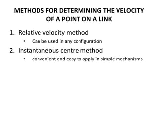
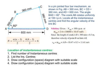
1. Two methods are described for determining the velocity of points on moving links: the relative velocity method and instantaneous center method.
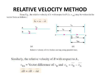
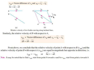
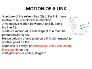
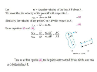
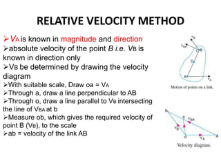
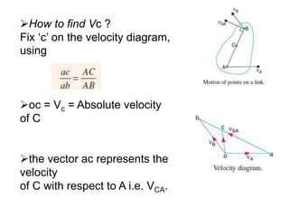
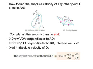
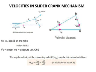
2. The relative velocity method constructs velocity triangles to find velocities. It can be used for any linkage configuration.
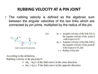
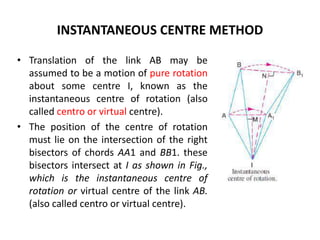
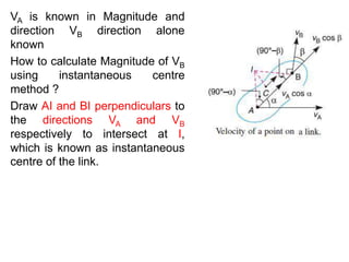
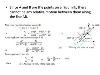
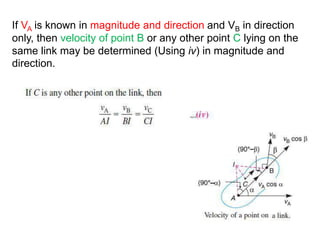
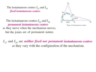
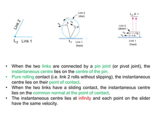
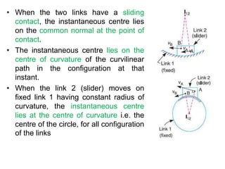
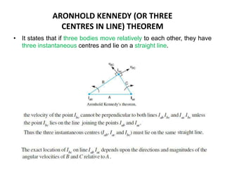
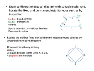
3. The instantaneous center method assumes the link rotates about a single center, making it easier for simple mechanisms. This center lies at intersections of bisectors.
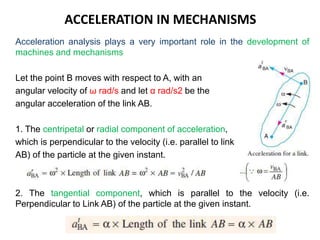
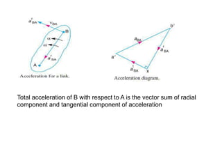
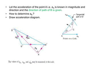
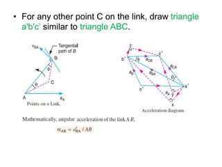
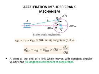
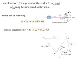
4. Acceleration analysis considers centripetal and tangential components. Total acceleration is the vector sum of these components. Acceleration diagrams can be constructed similarly to velocity diagrams.

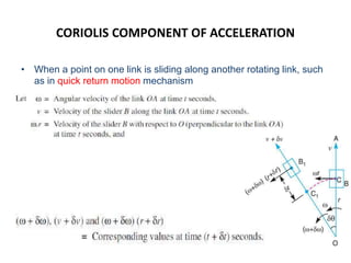
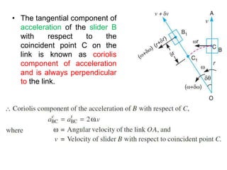
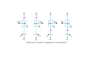


![Mechanics of machinery [Recovered].pptx](https://cdn.slidesharecdn.com/ss_thumbnails/mechanicsofmachineryrecovered-220808081831-415b3c97-thumbnail.jpg?width=640&height=640&fit=bounds)