
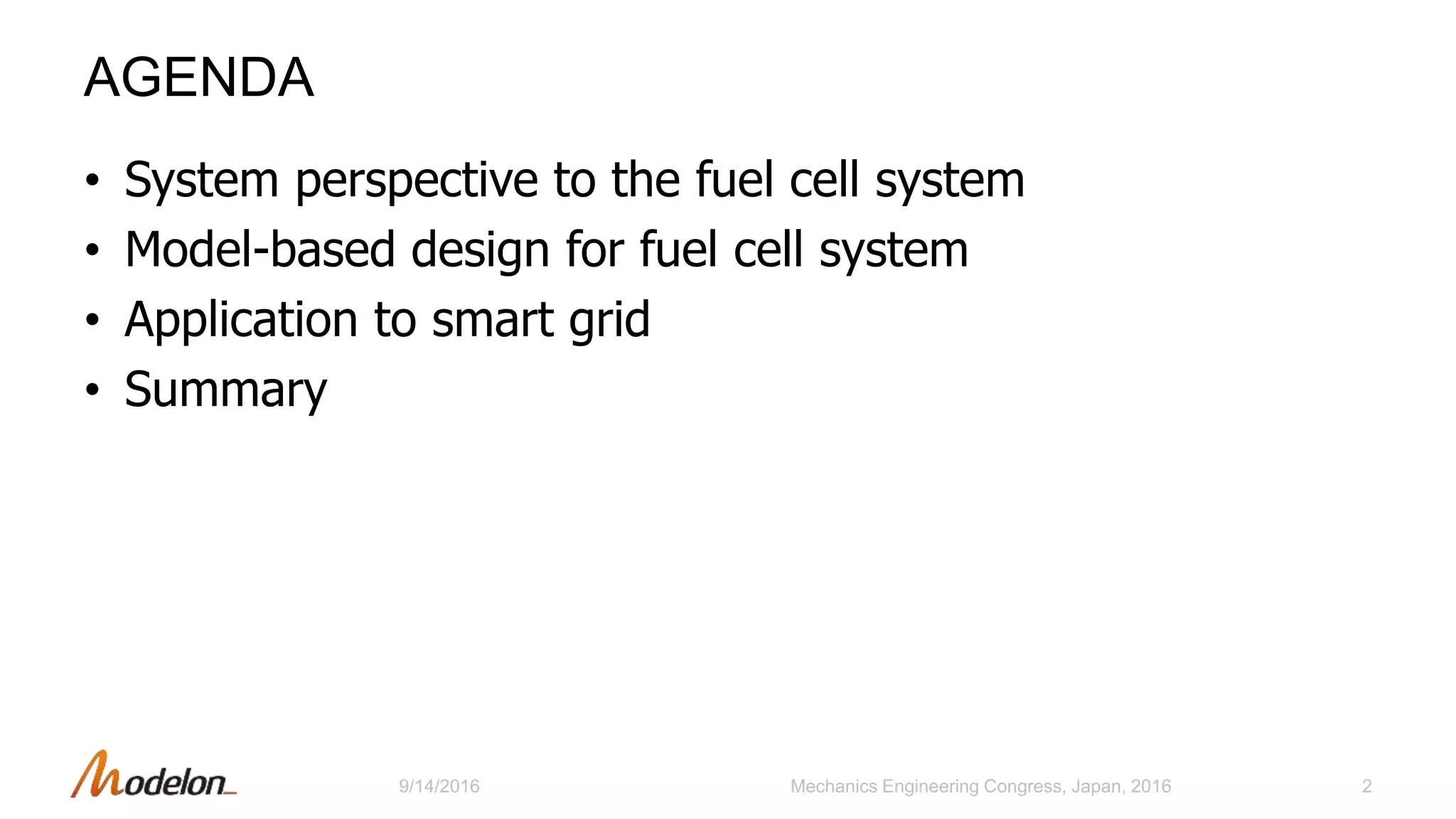
![MODELICA MODELING 2/3: OBJECT ORIENTED MODELING
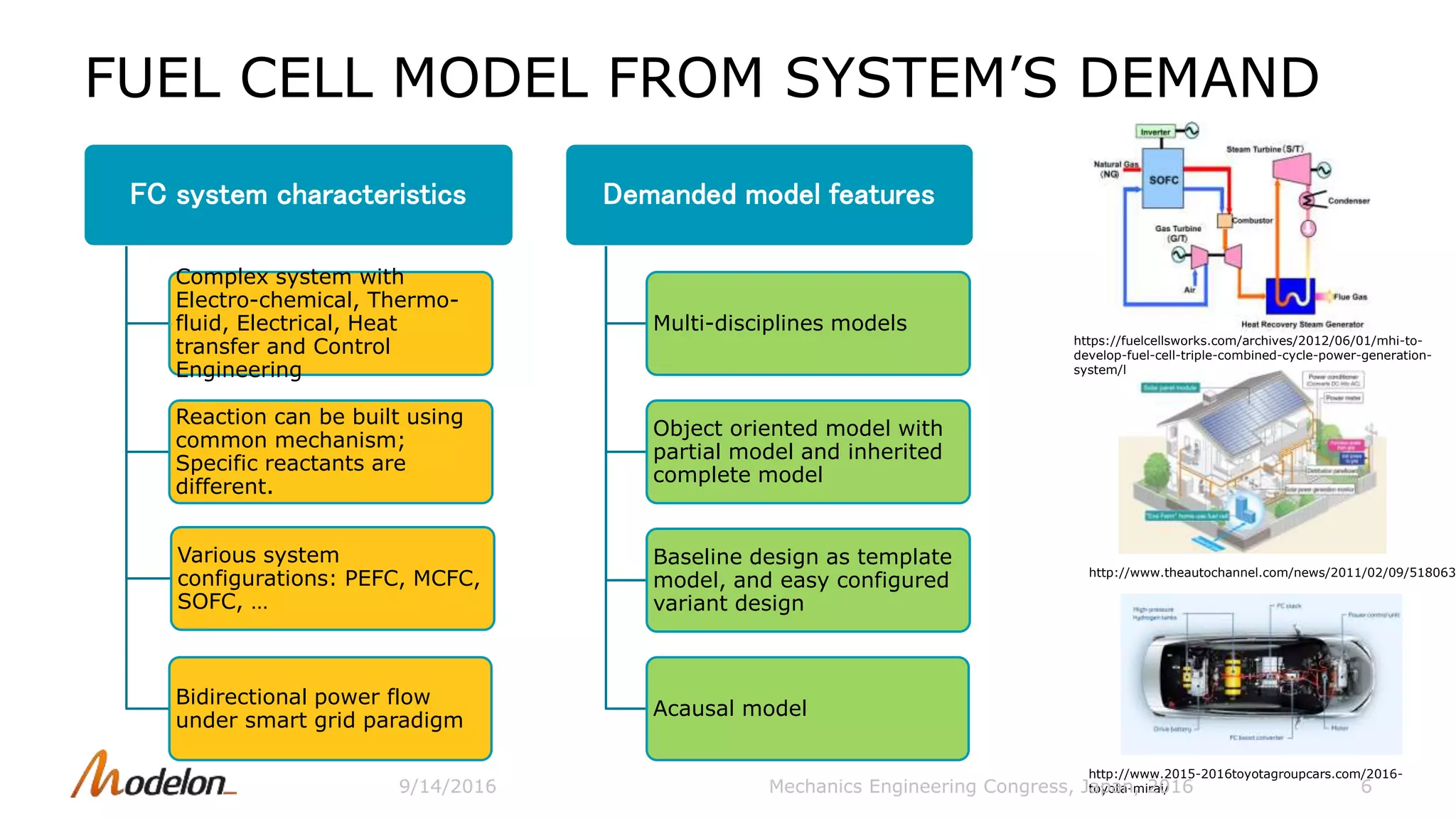
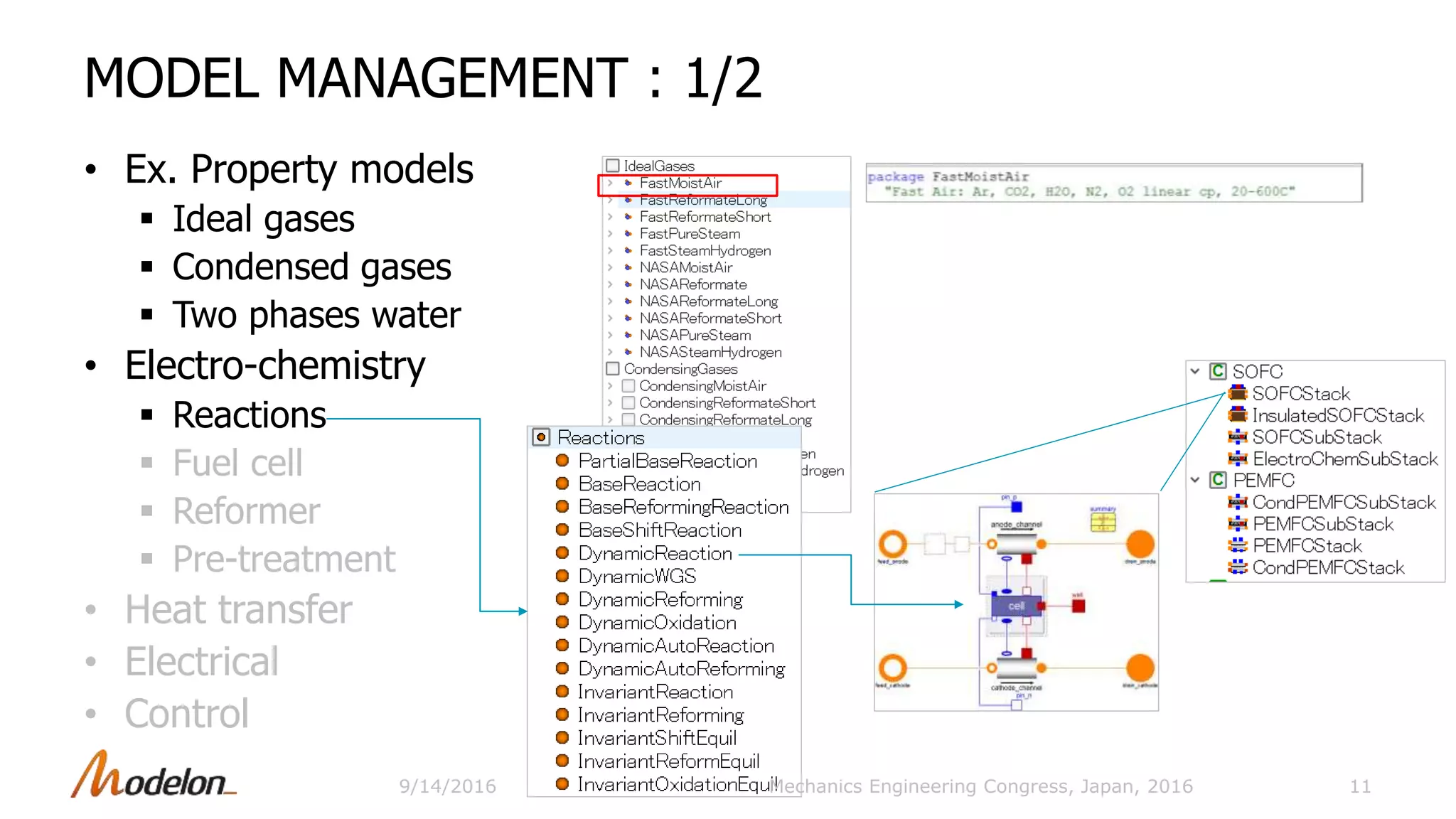
• Why Modelica?
Equation-based physics modeling
Object oriented modeling
Multi-disciplined
• Membrane example
connector
Interfaces to electrical, substance,
heat
9
∆𝑮 𝒇
𝟎
= − 𝒈 𝑯 𝟐
𝒐
+ 𝒈 𝑯 𝟐 𝑶
𝒐
−𝟎. 𝟓 𝒈 𝑶 𝟐
𝒐
connector MassPort
Medium medium;
Pressure p;
flow MassFlowRate m_flow;
SpecificEnthalpy h;
flow EnthalphFlowRate
H_flow;
MassFraction X[n.Xi];
flow MassFlowRate
mX_flow[nXi];
end MassPort;
Mechanics Engineering Congress, Japan, 20169/14/2016](https://image.slidesharecdn.com/modelonjsme-2016-mbdforfuelcellsystems-161104073731/75/Modelon-JSME-2016-Model-Based-Design-for-Fuel-Cell-Systems-9-2048.jpg)
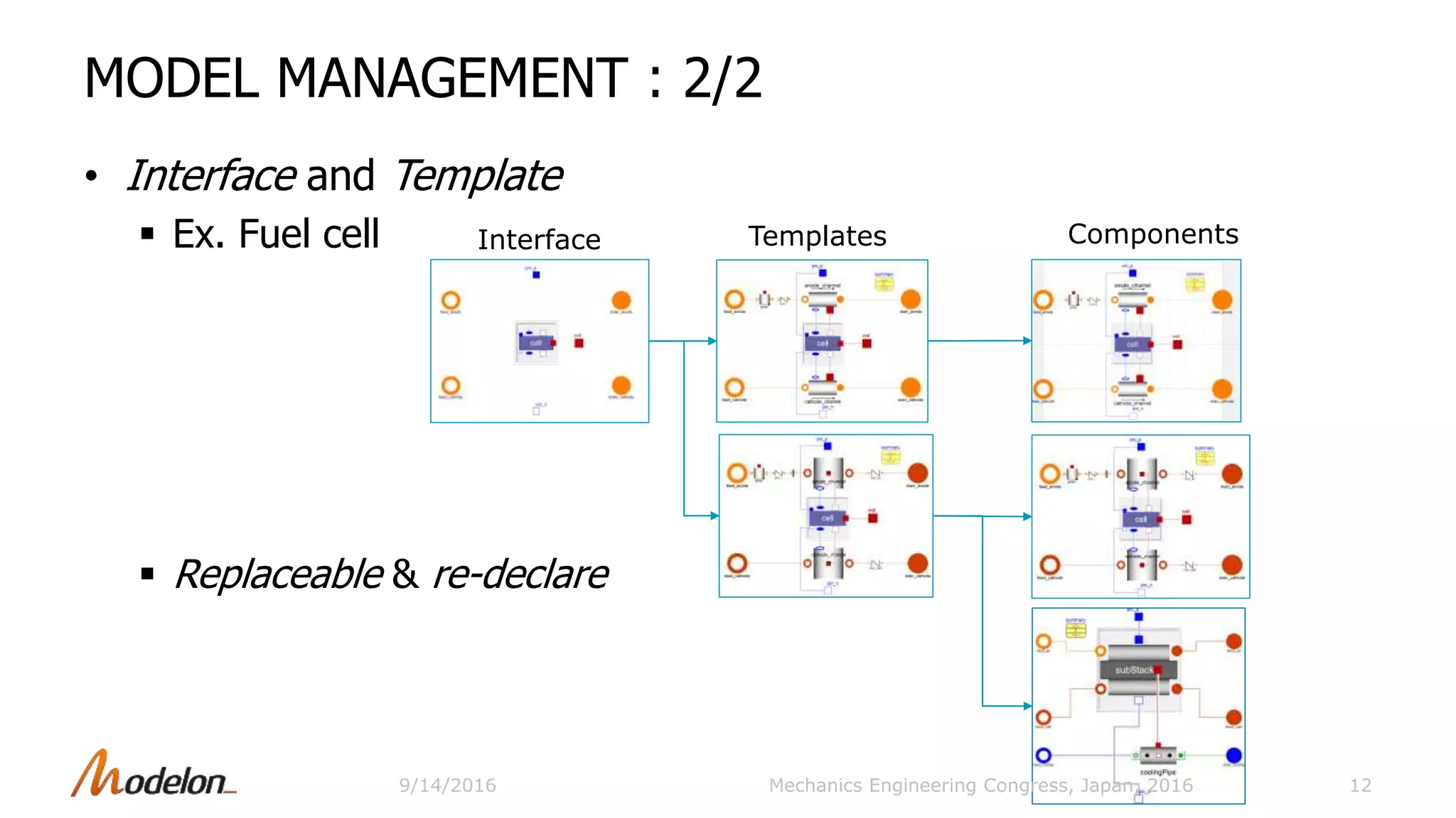
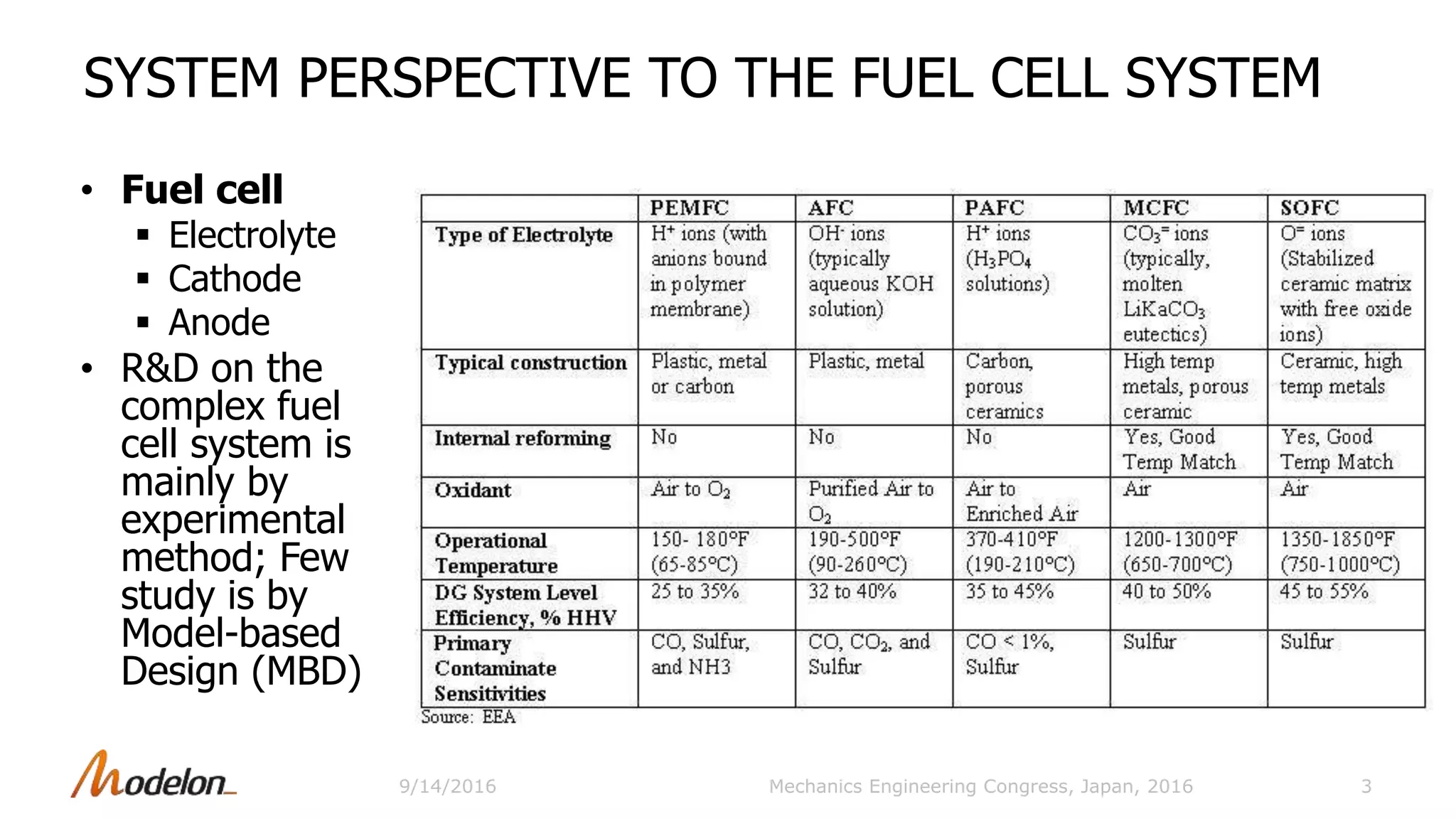
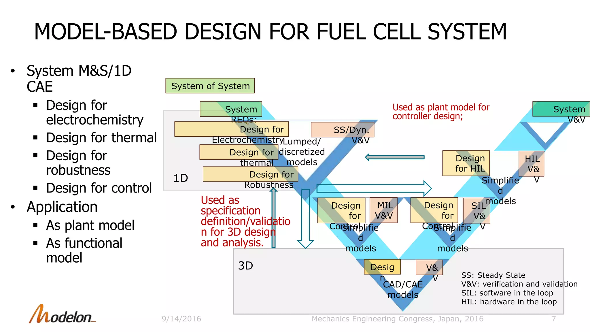
![SUB-SYSTEM TESTS
• Sub-system
Preprocessor
Micro gas turbine
13Mechanics Engineering Congress, Japan, 2016
microGasTurbine
GC T
Combustor
feedFuel
mT
.
drainAir
pT
feedAir
mT
.
ground
combustorcombustor
isBurning
true
inertia
J=J
air_loss
summary
generator
groundExc
idealCheckValve
drain
heat_port
feedFuel
feedAir
pin_p
pin_n
0 100 200 300 400 500 600 700 800 900 1000
0.0
0.5
1.0
1.5
2.0
2.5
feedFuel.fluidPort.p feedAir.fluidPort.p
0 100 200 300 400 500 600 700 800 900 1000
-0.025
-0.020
-0.015
-0.010
-0.005
0.000
0.005
feedFuel.m_flow feedAir.fluidPort.m_flow
0 100 200 300 400 500 600 700 800 900 1000
-200
-150
-100
-50
0
50
100
150
200
250
resistor.i[1] resistor.i[2] resistor.i[3]
0 200 400 600 800 1000
-4000
-2000
0
microGasTurbine.generator.flange.tau
Test model
Test model
flowSource_Water
mT
.
flowSource_NG
mT
.
flowSource_AirATR
mT
.
Boundary_hotgas
p T
flowSource_Hotgas
mT
.
flowSource_ATRHeat
mT
.
Boundary_ATRHeat
pT
Boundary_Reformate
pT
turbulentLoss
preprocessor
0.0H2
CH4 0.0
CO 0.0
CO2 0.0
H2O 0.0
Mole %
N2 0.0
O2 0.0
0.0 0.0
0.0 0.0
p(bar)h(kJ/kg)
T(degC)(g/s)
reformer
steamMix_TZ
AirHeater
Geometry_Record Initialization_Record summary
FuelHeater
fuelLoss
gasMix
NGMix
NGLoss
drain_Reformate
feed_NG
drain_NGHeat feed_SteamHeat feed_ATRHeatdrain_ATRHeat
feed_Water
feed_ATRAir
9/14/2016](https://image.slidesharecdn.com/modelonjsme-2016-mbdforfuelcellsystems-161104073731/75/Modelon-JSME-2016-Model-Based-Design-for-Fuel-Cell-Systems-13-2048.jpg)
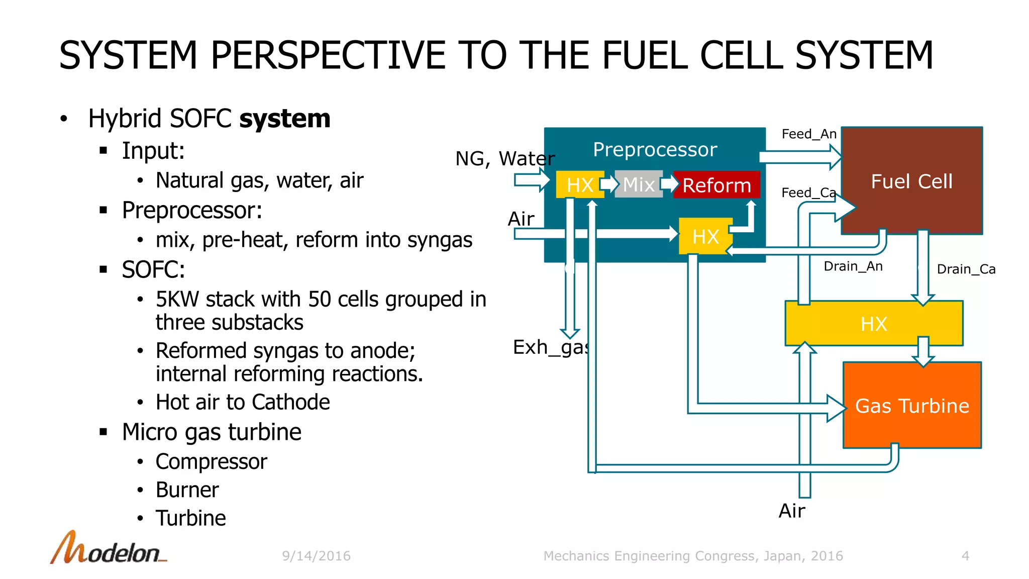
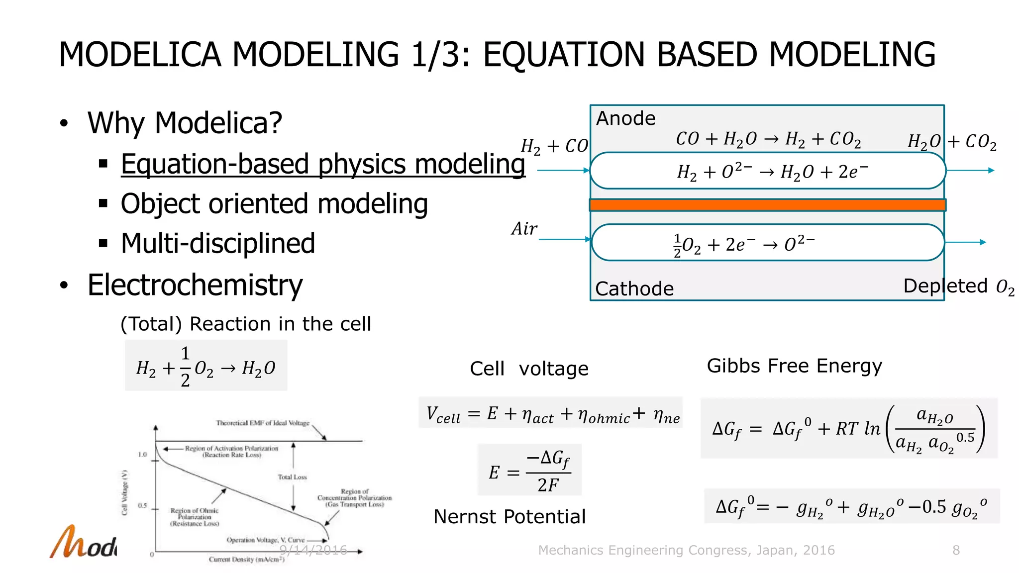
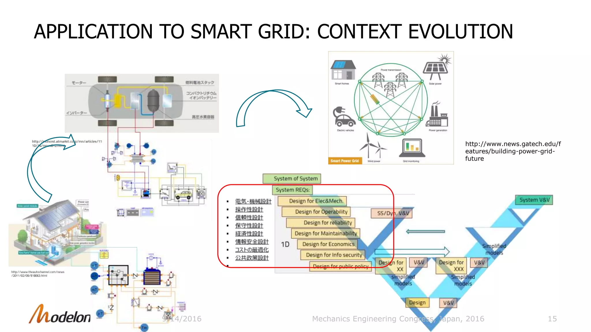
![HYBRID SOFC SYSTEM SIMULATION RESULT
• Analysis
Mass balance
Fuel cell
voltage-current
density relation
Thermal loss
Power-current
density relation
AC power
14Mechanics Engineering Congress, Japan, 2016
0 400 800 1200 1600 2000 2400 2800 3200 3600 4000
0.0E0
4.0E-5
8.0E-5
1.2E-4
1.6E-4
2.0E-4
checkMassBalanceSystem.mH_in
checkMassBalanceSystem.mH_out
checkMassBalanceSystem.mC_in
checkMassBalanceSystem.mC_out
Voltage [V] Power [W]
Stack
flowCathode
mT
.
ground
current
stack
summary
WaterSource
mT
.
NGSource
mT
.
ATRAirSource
mT
.
exhaustSink
p T
preprocessor
anLoss anVolume
cathVolume
microGasTurbine
GC T
Combustor
MGT_volOut
groundMGT
compMix
checkMassBalanceSystem
44.8 4478
0 1000 2000 3000 4000
0
50
100
150
current.i
0 1000 2000 3000 4000
35
40
45
50
55
current.v
500 1000 1500 2000 2500
40
42
44
46
48
50
stack.subStack[1].summary.j_external [A/m2]
current.v
0 400 800 1200 1600 2000 2400 2800 3200 3600 4000
0E0
1E5
2E5
3E5
4E5
resistor.resistor[1].LossPower
Mass balance
Fuel cell characteristic
Load current
AC power
0 400 800 1200 1600 2000 2400 2800 3200 3600 4000
750
760
770
780
790
800
810
stack.stackHeatLosses.topWall[1].T
stack.stackHeatLosses.topWall[2].T
stack.stackHeatLosses.topWall[3].T
stack.stackHeatLosses.topWall[4].T
Temperature of the stack top
500 1000 1500 2000 2500
40
42
44
46
48
50
0
500
1000
1500
2000
2500
3000
3500
4000
4500
5000
stack.subStack[1].summary.j_external [A/m2]
current.v stack.summary.PStkElec*
Voltage, power/current density relatio
9/14/2016](https://image.slidesharecdn.com/modelonjsme-2016-mbdforfuelcellsystems-161104073731/75/Modelon-JSME-2016-Model-Based-Design-for-Fuel-Cell-Systems-14-2048.jpg)


Rui Gao presented on model-based design for fuel cell systems using Modelica. The presentation discussed modeling a hybrid SOFC system from a systems perspective using equation-based and object-oriented Modelica models that integrate multi-disciplinary physics. Subsystem tests were conducted on models of the preprocessor and micro gas turbine. Simulation results showed mass balance, fuel cell voltage-current characteristics, thermal losses, and AC power output. Model-based design was identified as a promising approach for smart grid system development to enable bidirectional power flow.


![Coded Agents – with UiPath SDK + LangGraph [Virtual Hands-on Workshop]](https://cdn.slidesharecdn.com/ss_thumbnails/codedagentsdeck-251215155422-5497c599-thumbnail.jpg?width=640&height=640&fit=bounds)


