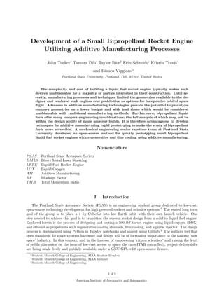
Senior Design Project - B.S. Mechanical Engineering (ITV Research and analysis)
AIAA_Space_2016_Proceedings__LFRE_(1)
1. Development of a Small Bipropellant Rocket Engine
Utilizing Additive Manufacturing Processes
John Tucker∗
Tamara Dib∗
Taylor Rice†
Erin Schmidt∗
Kristin Travis∗
and Bianca Viggiano‡
Portland State University, Portland, OR, 97201, United States
The complexity and cost of building a liquid fuel rocket engine typically makes such
devices unobtainable for a majority of parties interested in their construction. Until re-
cently, manufacturing processes and techniques limited the geometries available to the de-
signer and rendered such engines cost prohibitive as options for inexpensive orbital space
flight. Advances in additive manufacturing technologies provide the potential to prototype
complex geometries on a lower budget and with lead times which would be considered
unobtainable with traditional manufacturing methods. Furthermore, bipropellant liquid
fuels offer many complex engineering considerations; the full analysis of which may not be
within the design ability of many amateur builds. It is therefore advantageous to develop
techniques for additive manufacturing rapid prototyping to make the study of bipropellant
fuels more accessible. A mechanical engineering senior capstone team at Portland State
University developed an open-source method for quickly prototyping small bipropellant
liquid fuel rocket engines with regenerative and film cooling using additive manufacturing.
Nomenclature
PSAS Portland State Aerospace Society
DMLS Direct Metal Laser Sintering
LFRE Liquid Fuel Rocket Engine
LOX Liquid Oxygen
AM Additive Manufacturing
BF Blockage Factor
TMR Total Momentum Ratio
I. Introduction
The Portland State Aerospace Society (PSAS) is an engineering student group dedicated to low-cost,
open-source technology development for high powered rockets and avionics systems.1
The stated long term
goal of the group is to place a 1 kg CubeSat into low Earth orbit with their own launch vehicle. One
step needed to achieve this goal is to transition the current rocket design from a solid to liquid fuel engine.
Explored herein is the process of designing and testing a 500 lbf thrust engine using liquid oxygen (LOX)
and ethanol as propellants with regenerative cooling channels, film cooling, and a pintle injector. The design
process is documented using Python in Jupyter notebooks and shared using Github.2
The authors feel that
open standards for space systems hardware and design will be of increasing importance to the nascent ‘new
space’ industry. In this context, and in the interest of empowering ‘citizen scientists’ and raising the level
of public discussion on the issue of low-cost access to space the (non-ITAR controlled), project deliverables
are being made freely and publicly available under a GNU GPL v3.0 open-source licence.
∗Student, Maseeh College of Engineering, AIAA Student Member.
†Student, Maseeh College of Engineering, AIAA Member
‡Student, Maseeh College of Engineering.
1 of 8
American Institute of Aeronautics and Astronautics
2. A Jupyter Notebook is a sharable web application which allows for the live execution of code, namely
Python. Jupyter notebooks were utilized in order to create a development process for the design of a regener-
atively and film cooled liquid fuel rocket engine. The Jupyter Notebook forms a template for regeneratively
cooled chamber design. As design inputs are changed in the notebook, parametric curves, which form the
basis of the geometry file for 3D printing, are generated appropriately. This allows for quicker development
of geometry files for additive manufacturing and thus quicker lead times on engine prototyping. As addi-
tive manufacturing technology progresses and becomes widely accepted by industry, its capability in rocket
component design needs to be further studied and understood. Alloys used in Direct Metal Laser Sintering
(DMLS) have different strength, heat transfer, and surface roughness properties. This project aims to gain
insights on these properties and 3D printed combustion chamber performance.
II. Engine
Engine design is typically cost prohibitive for many amateur designers who may be able to contribute to
the advancement of low cost orbital space flight. The design process is cumbersome, and oftentimes does not
result in a final product that will successfully fire due to the complexity of engine design. Engineering tools
are not generally available, and an understanding of the full process is lacking. Due to the aforementioned
constraints, it is desirable for the amateur to have available a design tool which will aid in generating a
geometry capable of withstanding the stresses of a steady-state engine, while simultaneously producing a
desired thrust. A production engine was generated and built using the Jupyter Notebook. Table 1 shows a
variety of the theoretical engine parameters generated by the liquid fuel rocket engine (LFRE) notebook.
The LFRE Nozzle Jupyter Notebook3
allows the user to input desired design requirements; namely
thrust and material properties, to subsequently aid the designer in generating an acceptable geometry for
the specified requirements. NASA’s CEARUN tool4
is used to generate many of the initial design parameters
as inputs. Certain design constraints (fuel combination, mixture ratio, and chamber pressure) must be known
prior to utilizing the CEARUN tool, and should be selected according to needs of the engine design. After
inputs are provided, the basic geometry of the nozzle is determined. Furthermore, the analysis determines
the cooling capacity of the fuel used in regenerative passages resulting in parametric equations which describe
the chamber and nozzle contours, the inner and outer surfaces of the regenerative cooling passages, and the
external surface of the nozzle. The parametric equations may then be used to generate a printable 3D model
in combination with additive manufacturing processes.
The regenerative cooling passages constructed using the parametric equations are of uniform cross-
sectional area normal to the surface of the nozzle contour. These parametric equations were derived in
order to mathematically define a nozzle contour and its various cooling channel geometries in general such
that no geometry would have to be calculated by the designer, and a nozzle could be generated by virtue
of only the geometric parameters which make it unique.5
Full development of the parametric equations are
available for inspection, but are not provided here for the sake of brevity. This allows the cross sectional
area to be scaled as a means of controlling the velocity of the fuel in a particular regenerative passageway,
enabling better control of wall temperatures at any given axial position along the nozzle. Scaling functions
may be added as a design tool at a later date, but initial functions resemble a half period of a sine function
to scale along a desired length of nozzle in order to give a smooth and continuous scaling pattern along a
given section of the nozzle. Because the nozzle is parametrized, any parametric equation justifying a nozzle
section may simply be multiplied by a scaling function in order to more directly control cooling over specific
areas of the nozzle.
After generating parametric equations, a more detailed heat transfer analysis is undertaken. Properties
are evaluated along finite sections of the wall contour, and compared to the capacity of the specified coolant,
to allow the designer to analyze if a particular nozzle geometry is capable of reaching a thermal equilibrium
while remaining below the thermal and mechanical stress limits of the engine material and the boiling point
of the fluid. The analysis generates graphs of several key properties along the nozzle contour as shown in
figure 1. The major outputs of the Jupyter Notebook are a unique set of parametric equations with which a
liquid fuel rocket engine is created which utilizes regenerative and film cooling to protect the engine material
from yield due to thermal and mechanical stresses during thermally steady state combustion.
Correction factors are implemented into the Jupyter Notebook to address discrepancies between theoret-
ical values for various parameters and their empirically tested values. The primary correction factor to be
addressed after testing an engineering prototype should be the adiabatic wall temperature of the hot exhaust
2 of 8
American Institute of Aeronautics and Astronautics
3. Parameter, variable Unit Value
Nozzle force, F lbf 500
O/F weight mixture ratio, rw – 1.2
Fuel mixture percentage, rwfuel
– 0.595
Contraction ratio, εc – 10.5
Ratio of specific heats, γ – 1.12
Total chamber pressure, Pcinj psi 350.00
Throat pressure, Pt psi 202.73
Throat velocity, Vt ft/s 3464.05
Exit velocity, Ve ft/s 7804.45
Total mass flow rate, ˙w lb/s 2.06
Stagnation temperature, Tcns
◦
R 5487.10
Adiabatic wall temperature at inlet, Tawi
◦
R 4389.64
Adiabatic wall temperature at throat, Tawt
◦
R 4379.47
Specific Impulse, Is lb · s/lb 242.37
Characteristic velocity, c∗ ft/s 5325.59
Chamber volume, Vc in3
27.35
Chamber cross sectional area, Ac in2
10.26
Throat radius, rt in 0.558
Exit radius, re in 1.037
Wall thickness, t in 0.01820
Cooling channel base width at throat, bt in 0.02522
Cooling channel base width at exit, be in 0.06192
Cooling channel effective radius at throat, rccht
in 0.01261
Cooling channel effective radius at exit, rcche
in 0.03096
Cooling channel hydraulic diameter, d in 0.04671
Cooling channel total area, Ac in2
1.16537
Number of cooling channels, n – 82
Coolant side heat transfer coefficient, hc Btu/(in2
· s ·◦
F) 0.15609
Required heat flux, ˙q Btu/(in2
· s) 27.72
Coolant capacity, Qc Btu/s 341.68
Combined tangential stress at nozzle exit, Ste
psi 32224.43
Combined tangential stress at throat, Stt psi 31554.40
Table 1. Parameters obtained from the Jupyter Notebook for the production engine chamber and nozzle
design.
3 of 8
American Institute of Aeronautics and Astronautics
4. 0 1 2 3
Nozzle position, x, (in)
0
0.5
1
1.5
2
2.5
MachNumber,Ma
0 1 2 3
Nozzle position, x, (in)
4000
4500
5000
5500
Temperature,T(◦
R)
0 1 2 3
Nozzle position, x (in)
0
5
10
15
20
25
30
Heatflux,˙q(Btu/in2
·s)
Figure 1. LFRE Jupyter Notebook sample output for Mach number, temperature and heat flux along the
length of the developed nozzle. For a complete set of parameters plotted as a function of nozzle position see
the Github repo.3
gas due to film cooling. Models for film cooling are not well established, and it is important to determine
a correction factor for a particular engine in order to accurately predict the resulting physical properties of
subsequent iterations of engine prototypes. This will allow a designer to predict the flow rates and pressure
drops of propellants with enough accuracy to design a propellant feed system capable of delivering required
pressure to an engine without the need to iterate through many costly test stand designs.
Engine Features
The first engine prototype shown in figure 2 is intended to produce 500 lbf. It is produced by a DMLS 3D
printing process and made from high temperature aluminum alloy, AlSI10Mg. External to this project, a
test stand is being built that is capable of delivering fuel at approximately 500 psi to the fuel manifold, which
is located at the base of the nozzle bell. Upon collection, the fuel is directed through regenerative cooling
channels. The fuel is then delivered to a collection chamber. Care should be taken to limit the overhang
angles within the larger geometries of the collection chamber. This limit is dictated by the particular 3D
printing process which is being utilized. The designer should consider the print orientation and maximum
overhang angle. The presented prototype was printed with a maximum overhang angle of 45◦
, and the design
resulted in minimal use of support material. Upon collection, the fuel is directed to film cooling ports, shown
in figure 3; of which the size and quantity are optimized by the Jupyter Notebook. Remaining fuel is then
utilized as propellant, which is directed around a pintle injector, described in section III. After injection and
combustion occur, the propellants are directed through a de Laval nozzle design based on Rao’s parabolic
bell approximation.6
DMLS uses high energy pulse CO2 lasers (carbon dioxide laser) to fuse metal particles together, layer-
by-layer, to form a solid product. The process is done in a powder bed that inherently provides support
material for any overhanging features. Because of this, complex features and internal passageways are
possible utilizing DMLS that are not possible with traditional machining approaches. Incorporating DMLS
manufacturing allows the designer to work towards the ’ideal’ design for a rocket engine without the added
burden of considering machinability. Features such as regenerative cooling channels no longer require special
machining strategies for incorporation into a design. They are instead printed directly into the nozzle
contours simply and accurately with only feature size and overhang angles as constraints.
III. Pintle Injector
There are several possibilities for the selection of the injector. A 500 lbf thrust engine has low fuel
mixing requirements; as long as the mass flow rates and momentum ratios are satisfied, many different
designs will suffice. Swirl injectors, as well as impinging jet injectors were considered; however, these designs
are more complex and potentially more difficult to integrate with 3D printed cooling channels. As a result, an
interchangeable pintle injector design based on research published by Santoro was selected.7
A pintle injector
will be fixed to the engine via bolts or machine screws, making it relatively easy to remove and replace if
alterations are necessary. Additionally, pintle injectors are less susceptible to combustion instabilities and
are potentially throttle-able; features that will benefit future PSAS liquid engine designs.8
The pintle injector is responsible for delivering the liquid oxygen to the combustion chamber. 316 stainless
4 of 8
American Institute of Aeronautics and Astronautics
5. Figure 2. Final assembly cross section drawing of the rocket engine. Areas in red show the regenerative
cooling channels and the path the fuel takes through the engine. Areas in green are the liquid oxygen flow
path.
Figure 3. Final design cross section drawing of the nozzle bell, the nozzle and fuel manifolds are manufactured
as a single part. The nozzle is a parabolic approximation of a de Laval converging-diverging nozzle.
steel was chosen as the pintle injector material because of its LOX compatibility and thermal resistance
qualities. The liquid oxygen travels down the center of the pintle and leaves the LOX holes at a 90◦
angle
to the original direction of travel. The liquid oxygen exiting the pintle holes collides with the annulus fuel
stream and creates an atomized mixture. The oxygen holes and fuel gap have been sized to achieve near
equal flow momentum of each propellant resulting in a TMR near unity to ensure the trajectory of the
mixture inside the combustion chamber is ∼45◦
. The design for the pintle injector is shown in figure 4.
Currently there is little published data on the design and construction of pintle injectors. Therefore an
extensive documentation of the design process has been outlined in the Github repository. Using the Jupyter
Notebook in Github, radii for the LOX holes and the fuel annulus were determined from inputs for required
chamber pressure and propellant mass flow rates. The dimensions of the radii can be adjusted according
to recommended blockage factor (BF) and total momentum ratio (TMR) values provided by Woodward.9
The notebook is constructed for ease in calculations for an iterative process. Table 2 shows the theoretical
parameters generated by the Jupyter Notebook that pertain to the design of the current pintle injector.
5 of 8
American Institute of Aeronautics and Astronautics
6. (a) (b)
Figure 4. Pintle LOX holes and fuel annulus inside combustion chamber (a) and Stainless Steel pintle injector
design (b).
Parameter, variable Unit Value
Pintle center LOX flow rate, ˙wox lb/s 1.13
Outer annulus ethanol flow rate, ˙wf lb/s 0.94
Pintle outer radius, Rp in 0.14
Pintle inner radius, r in 0.06
Fuel annulus radius, Ra in 0.152
Annulus gap, t in 0.012
Injector pressure drop, ∆P psi 70
Pintle hole diameter, dh in 0.045
Number of pintle LOX holes, N – 8
Theoretical Blockage Factor, BF – 0.41
Theoretical Total Momentum Ratio, TMR – 0.97
Table 2. Parameters obtained from the Jupyter Notebook for the current pintle injector design.
6 of 8
American Institute of Aeronautics and Astronautics
7. IV. Ongoing and Future Work
All entities of the printed production engine, shown in figure 5, must still be tested, including the injector
and nozzle. The regenerative cooling channels of the nozzle will be cold flow tested prior to any hot fires. The
pintle injector has been designed and is in the midst of being machined; it will be cold flow tested prior to
being attached to the nozzle. The ignition system is currently being designed as well as the instrumentation
to test fire the engine.
Figure 5. Printed engine to be cold tested and hot fired.
A future iteration of the Jupyter Notebook would include constant hydraulic diameter as an output rather
than a constant cross sectional area, in order to give the designer a unit flow velocity along the channels.
The flow velocity could then be scaled as desired around areas of high heat transfer such as the throat.
V. Conclusion
To the knowledge of the authors, no other open-source method for quickly prototyping liquid fuel engines
exists. The first iteration of this engine will be tested on a test stand in 2016. The results obtained from
the cold tests and hot fire of the engine will aid in future iterations and give insight into the validity of
the equations utilized for this engine. 3D printed engines are just beginning to be developed and tested
by industry, and few have been tested in flight. Additive manufacturing has opened the door for design
innovation, low cost development, and amateur group access to space.
Acknowledgments
The authors are grateful to PSAS for funding and initiating this project, Faculty Advisor Dr. Derek
Tretheway for his advice and guidance and Cam Yun for his work on the project. The authors are also
grateful to Robert Watzlavick, David Gregory, and Armor Harris for their advice, and the Oregon Air
National Guard for their guidance on LOX handling. Finally the authors are indebted to i3D MFG for
their ongoing support with additive manufacturing and Machine Sciences Corporation for their support with
traditional machining.
References
1“Portland State Aerospace Society,” http://psas.pdx.edu/, Accessed: 2016-08-17.
2“LFRE GitHub Repository,” https://github.com/psas/liquid-engine-capstone-2015, Accessed: 2016-08-17.
3“Nozzle Construction Jupyter Notebook,” https://github.com/psas/liquid-engine-capstone-2015/blob/master/
Nozzle_Construction/LFRE.ipynb, Accessed: 2016-08-17.
7 of 8
American Institute of Aeronautics and Astronautics
8. 4“CEARUN,” https://cearun.grc.nasa.gov/, Accessed: 2016-08-17.
5“Derivations of Parametric Equations defining a Rao Parabolic Bell Approximation,” https://github.com/psas/
liquid-engine-capstone-2015/blob/master/Nozzle_Construction/Cooling_Channel_Geometry_complete.pdf, Accessed:
2016-08-17.
6Rao, G. V. R., “Recent developments in rocket nozzle configurations,” ARS journal, Vol. 31, No. 11, 1961, pp. 1488–1494.
7Santoro, R. J. and Merkle, C. L., “Main Chamber and Preburner Injector Technology,” 1999.
8Dressler, G. A. and Bauer, J. M., “TRW pintle engine heritage and performance characteristics,” AIAA paper, Vol. 3871,
2000, pp. 2000.
9Woodward, R., Miller, K., Bazarov, V., Guerin, G., Pal, S., and Santoro, R., “Injector research for Shuttle OMS upgrade
using LOX/ethanol propellants,” AIAA Paper, 1998, pp. 98–3816.
8 of 8
American Institute of Aeronautics and Astronautics