Download to read offline
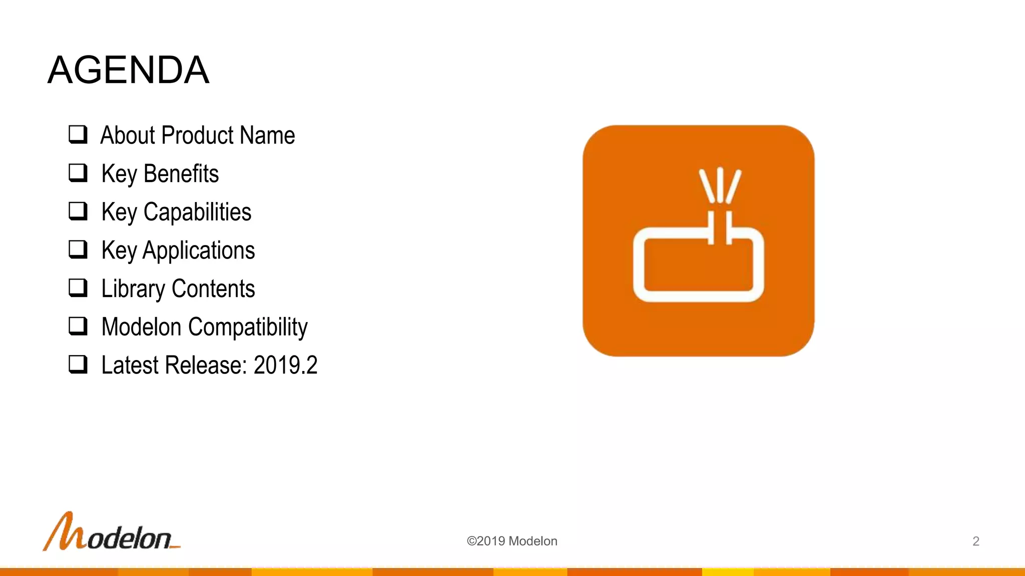
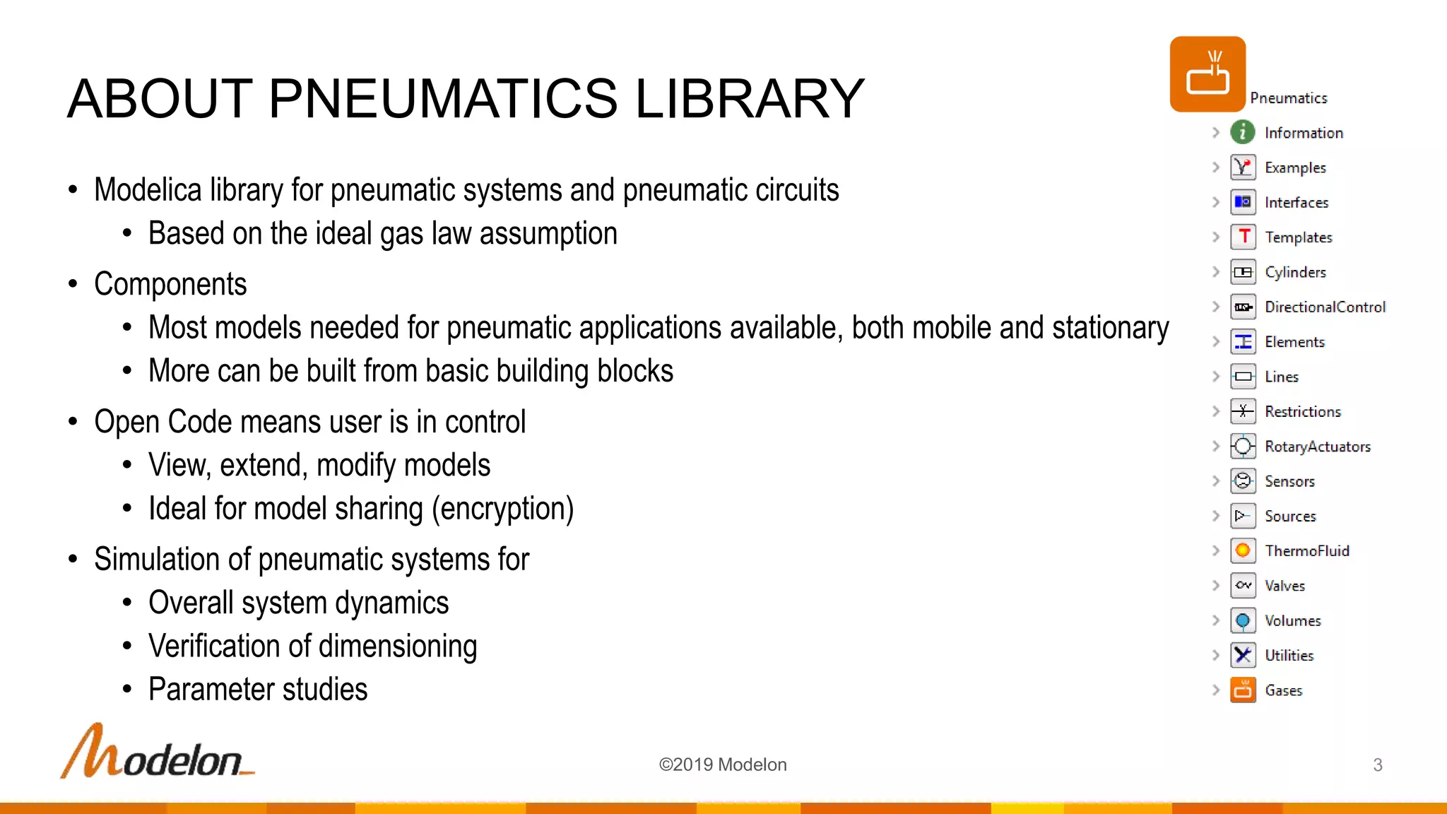
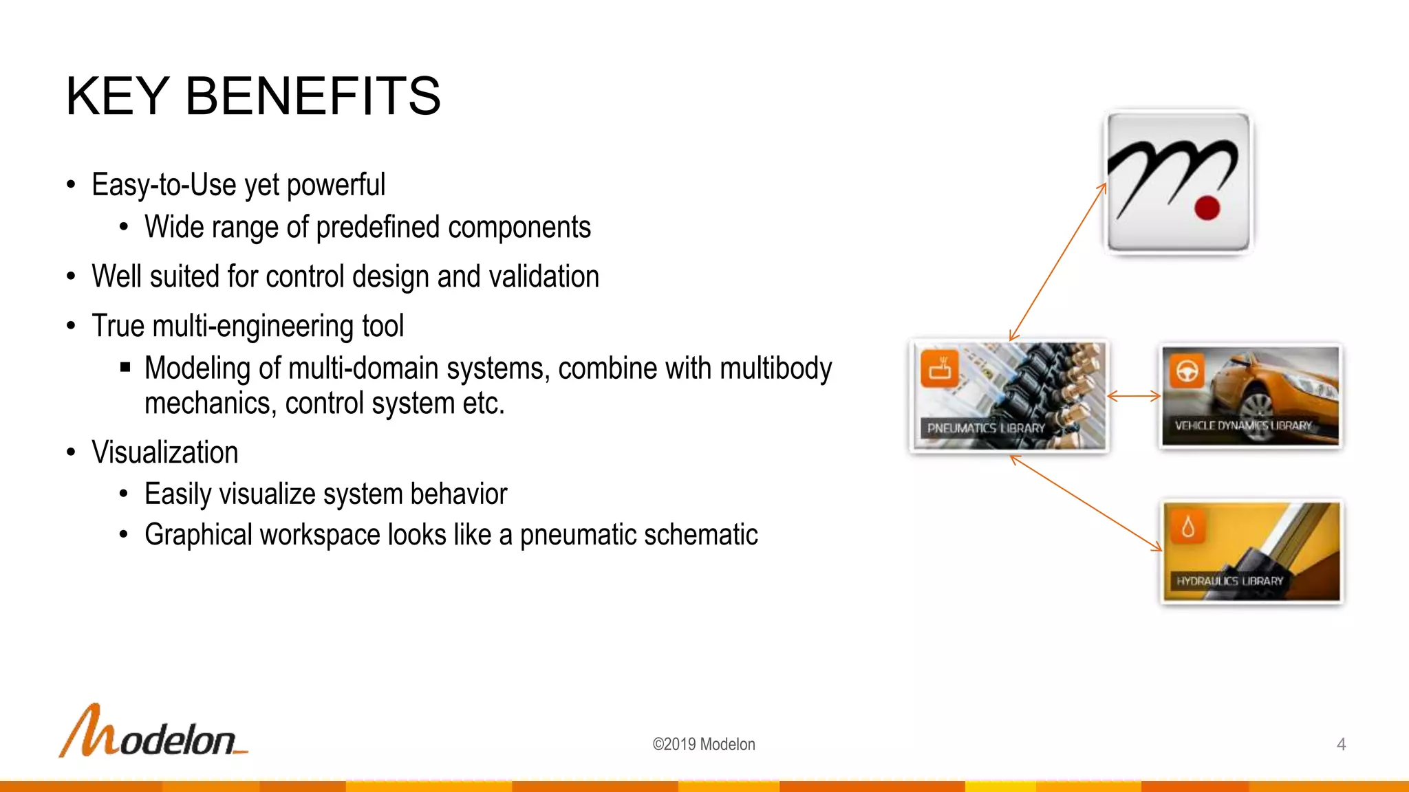
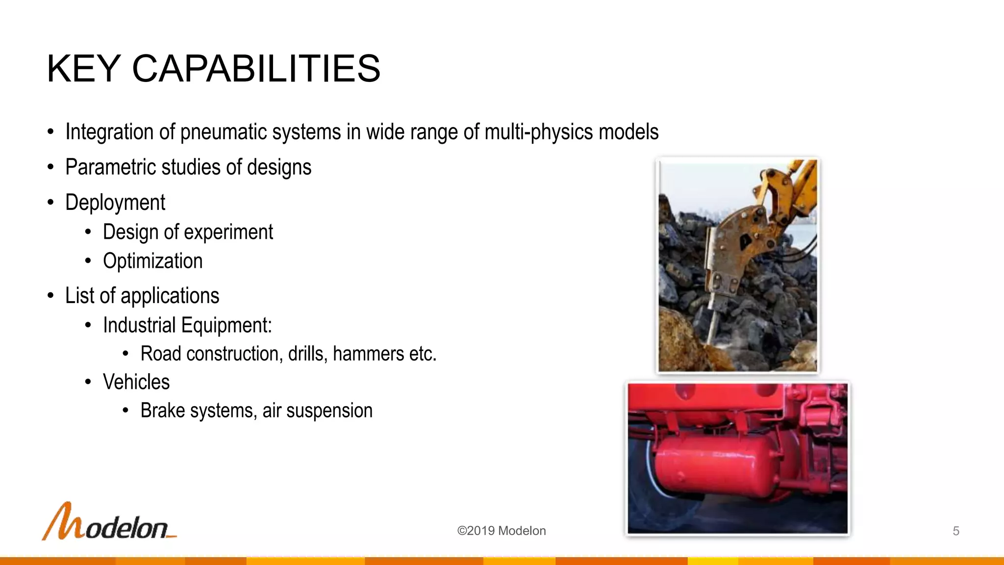
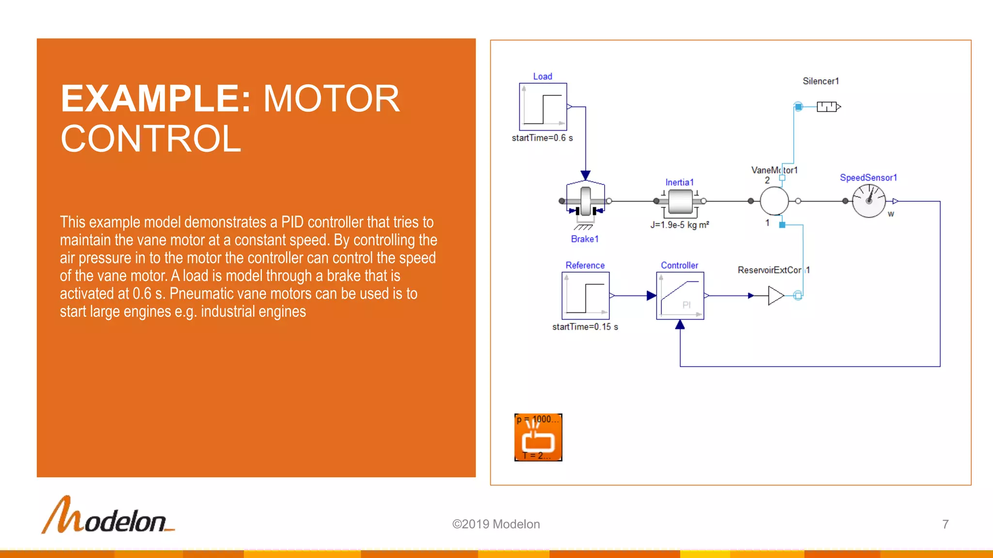
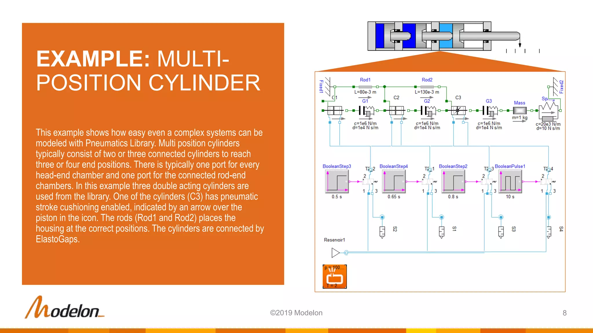
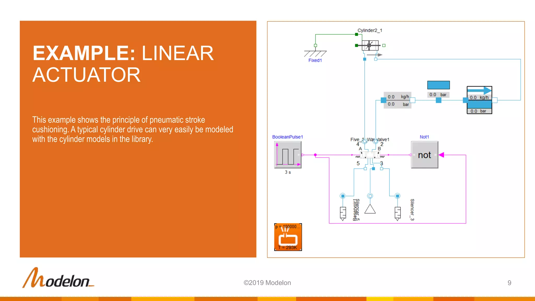
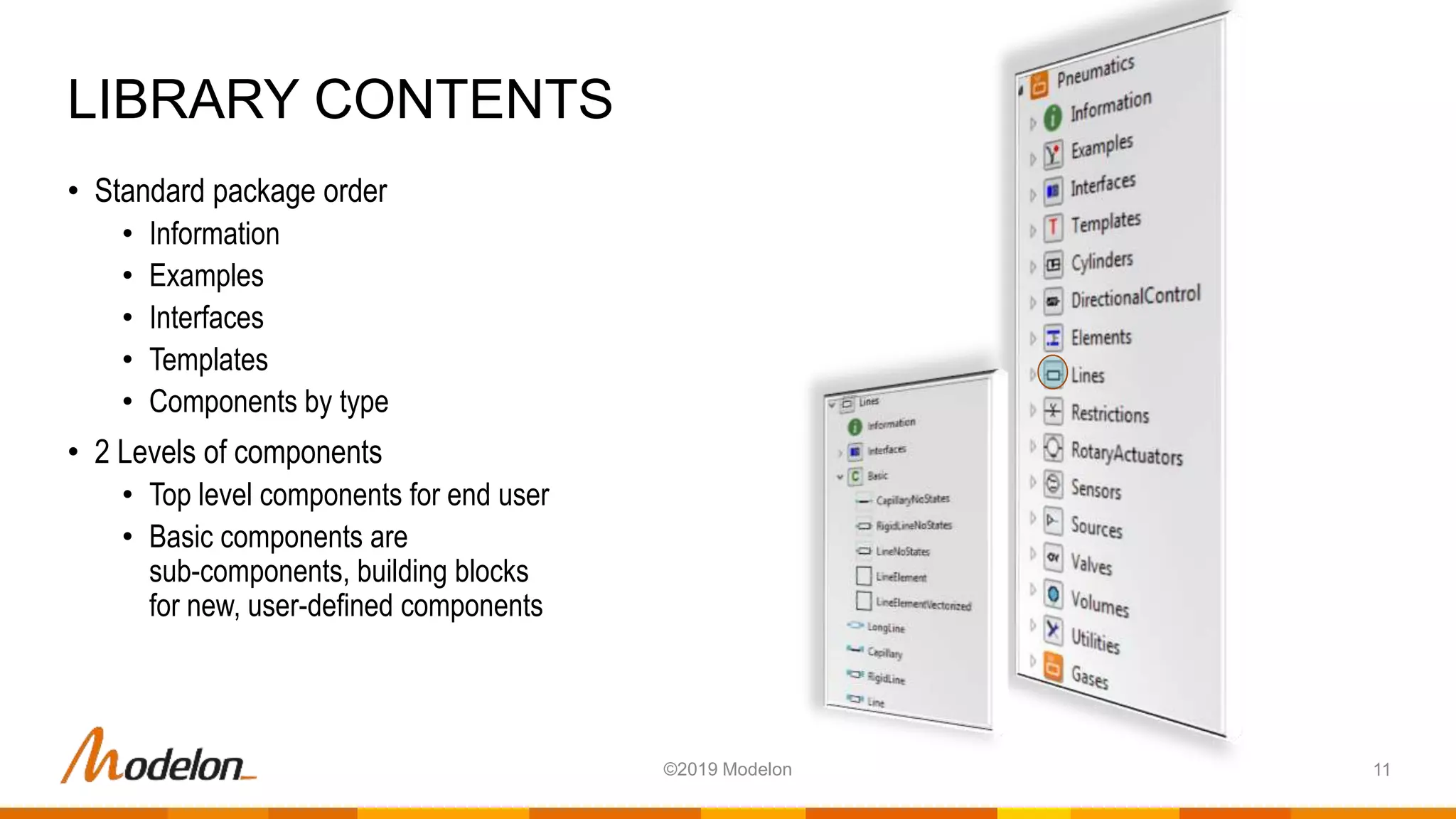
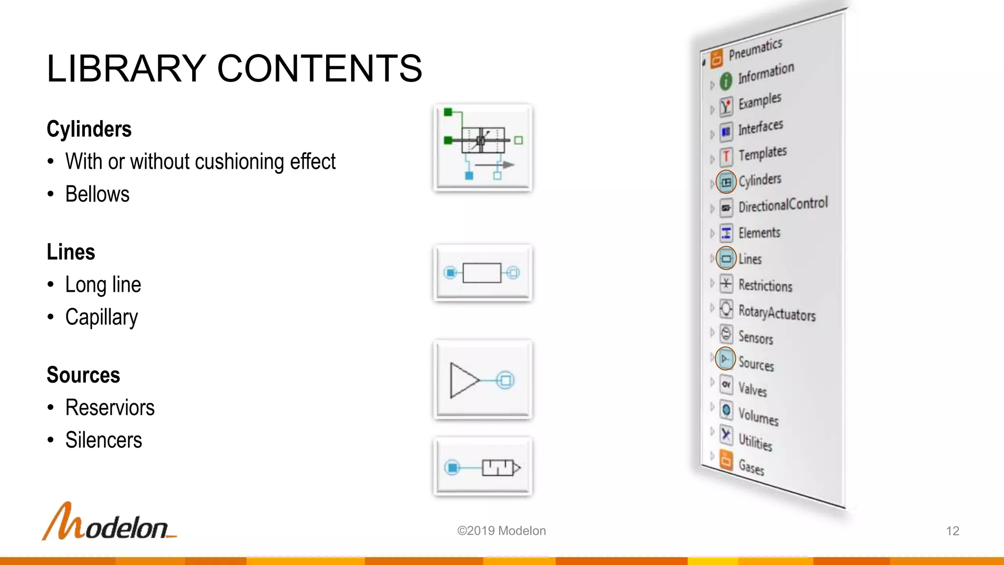
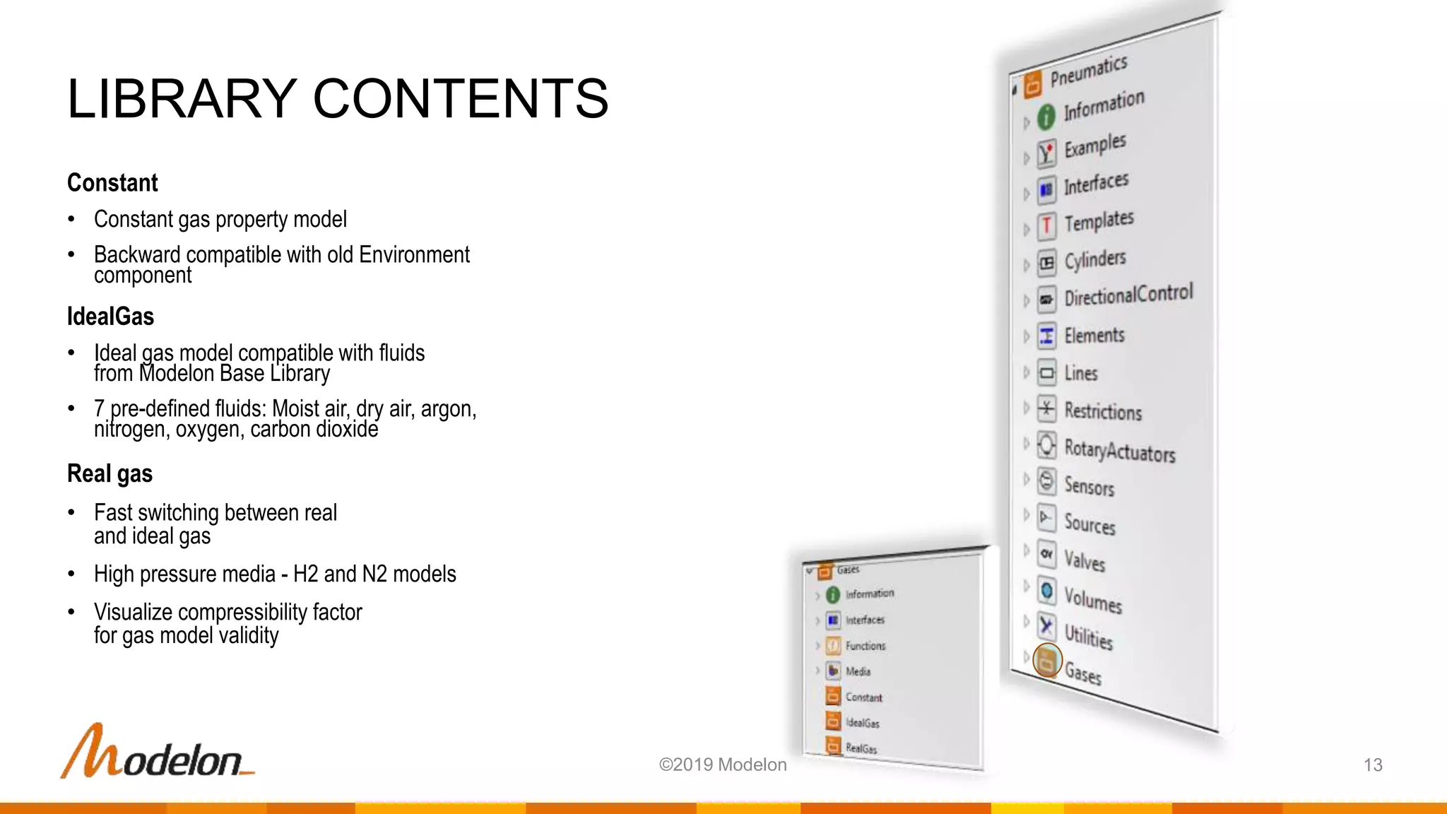
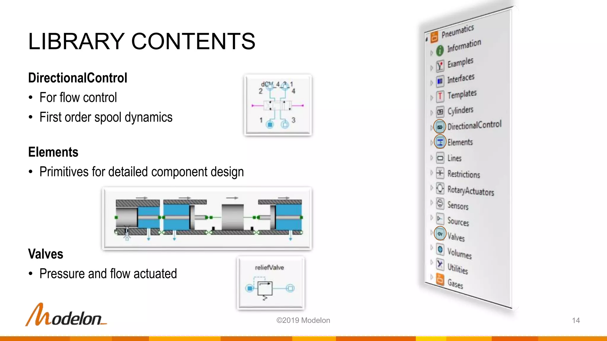
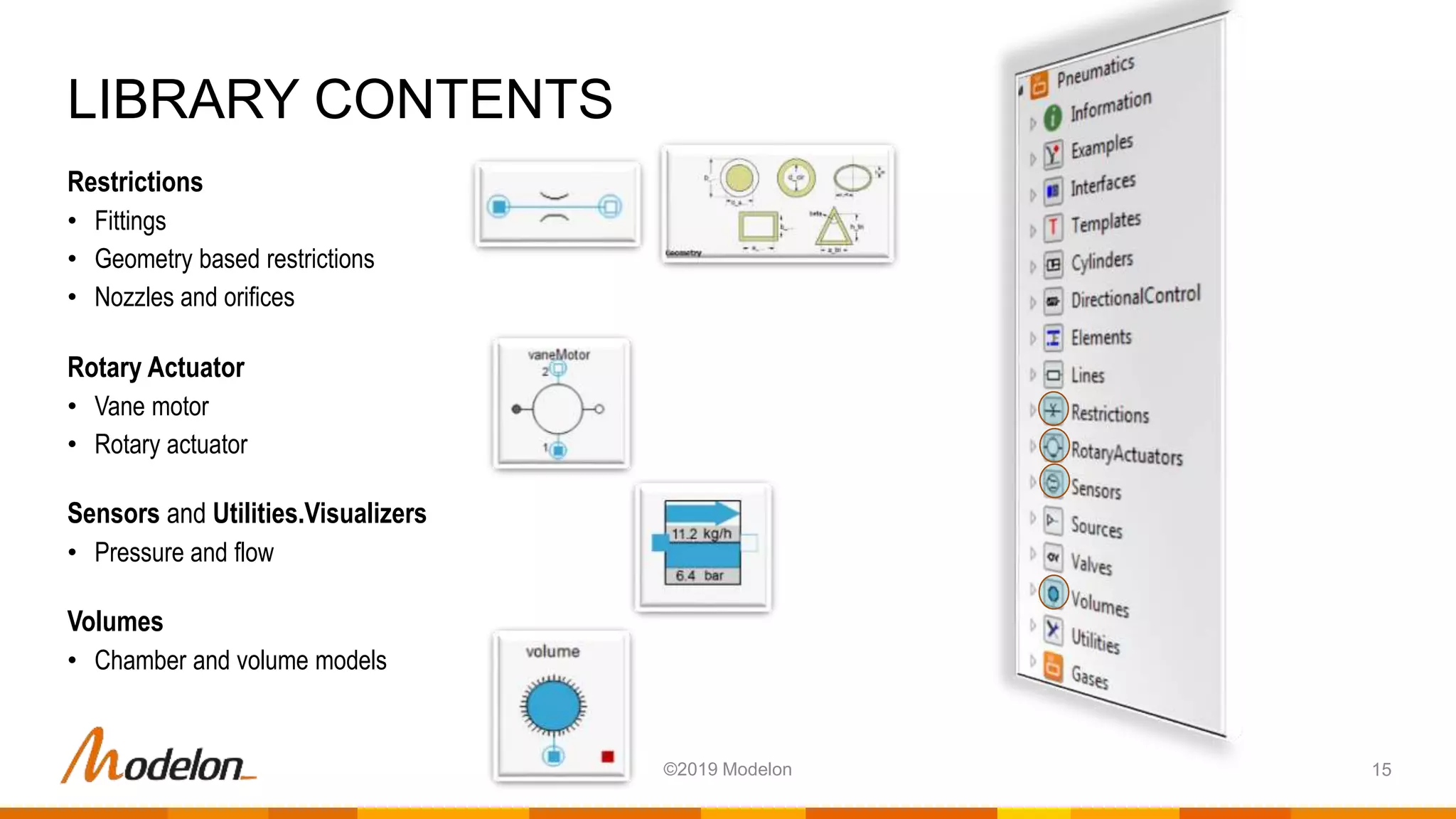
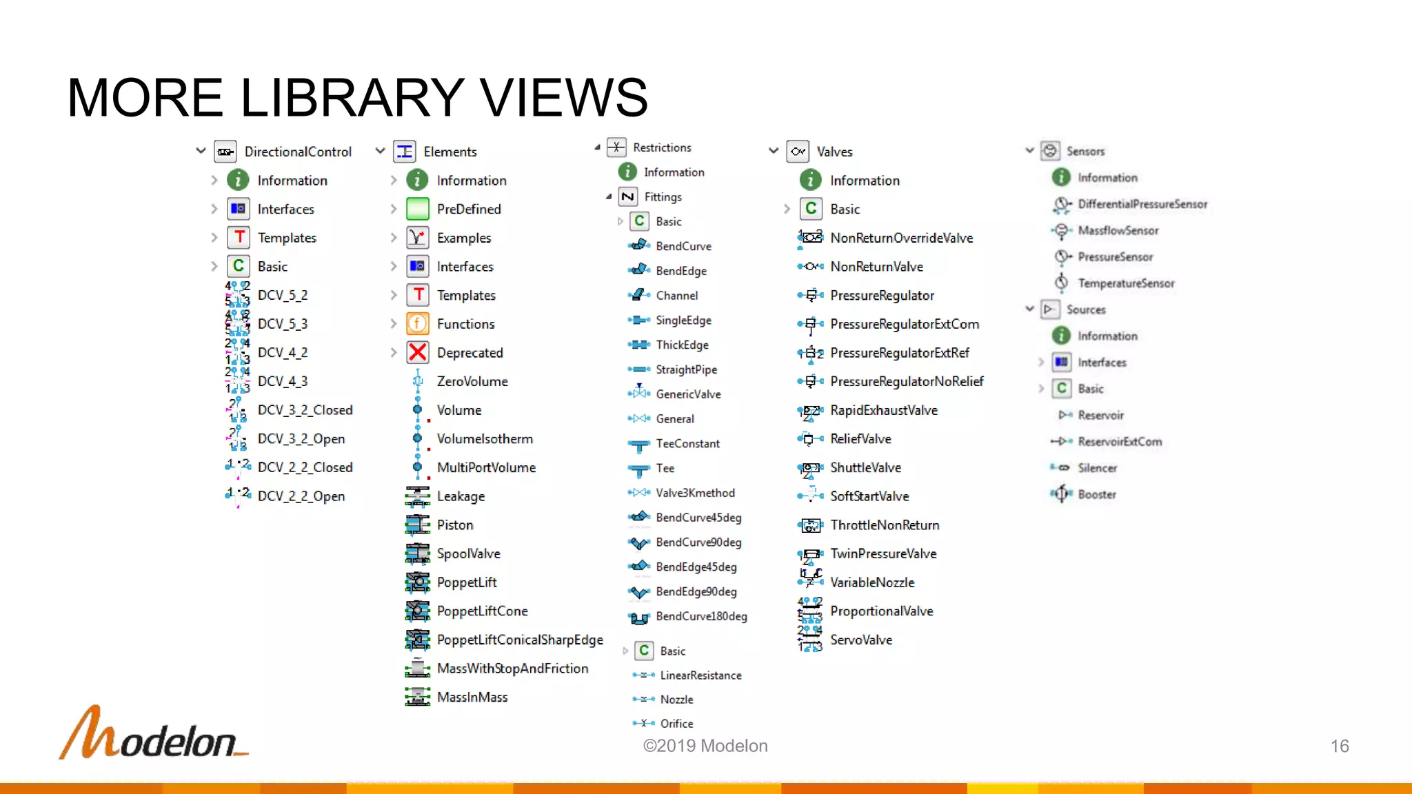
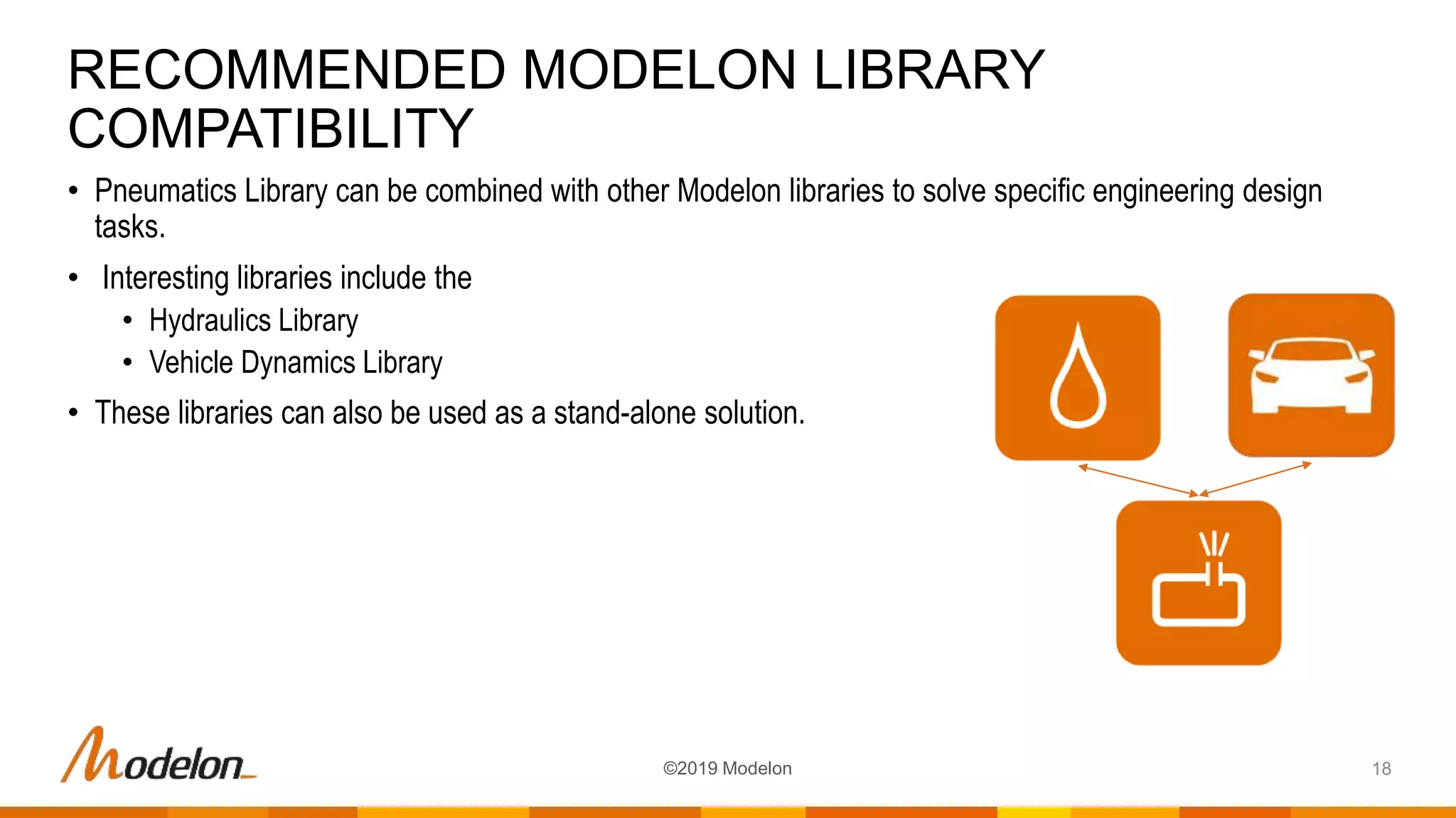
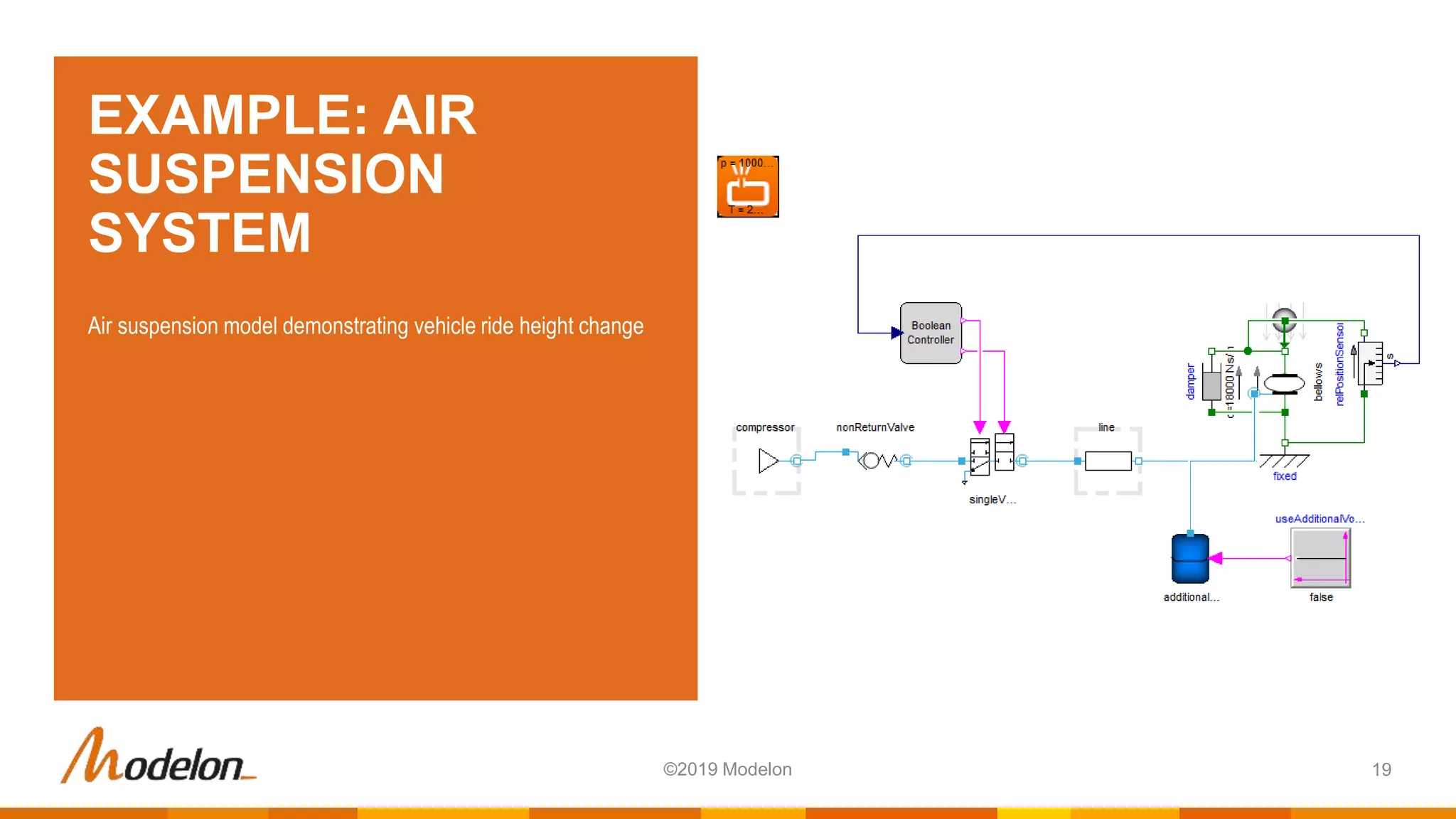
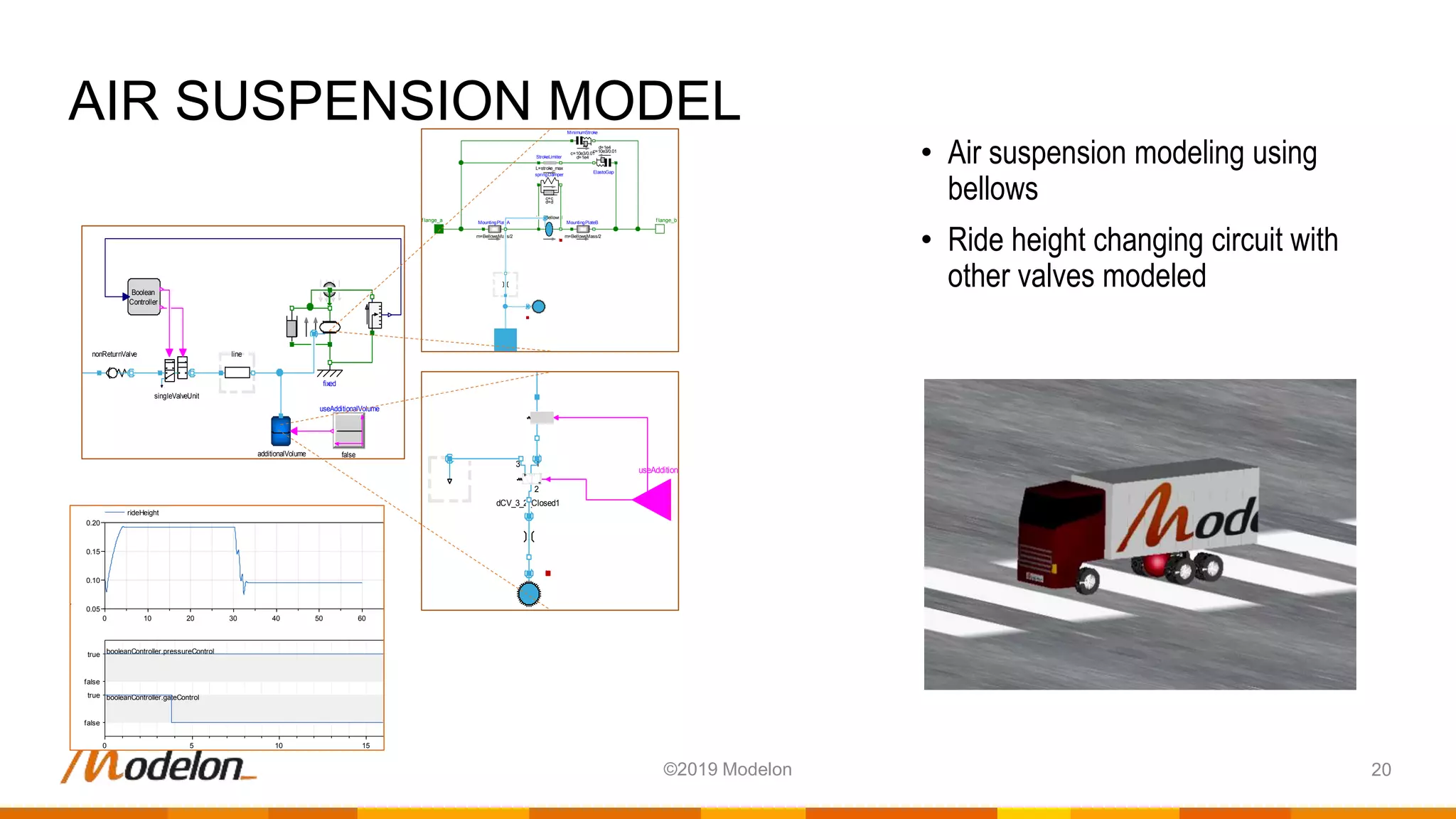
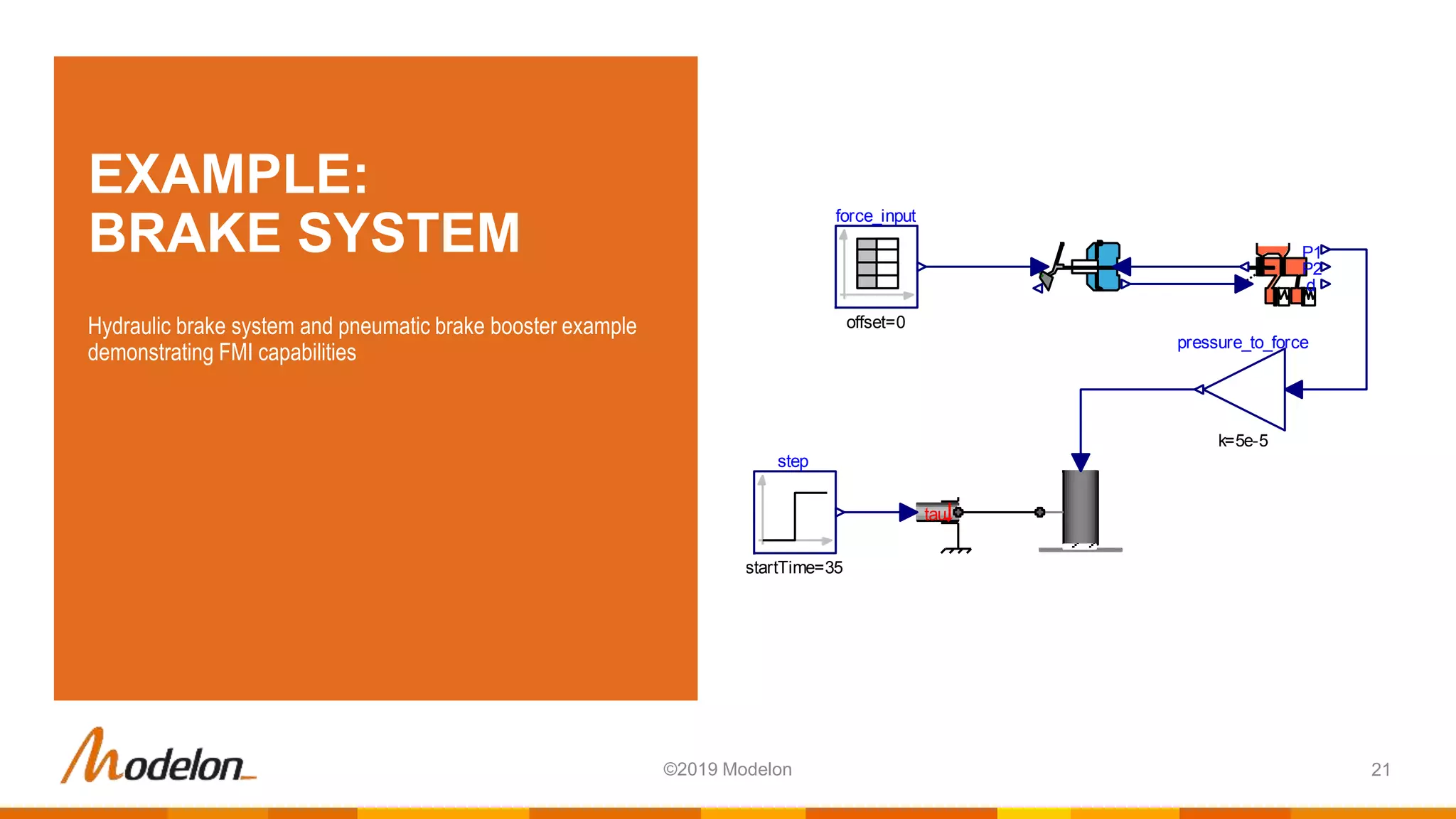
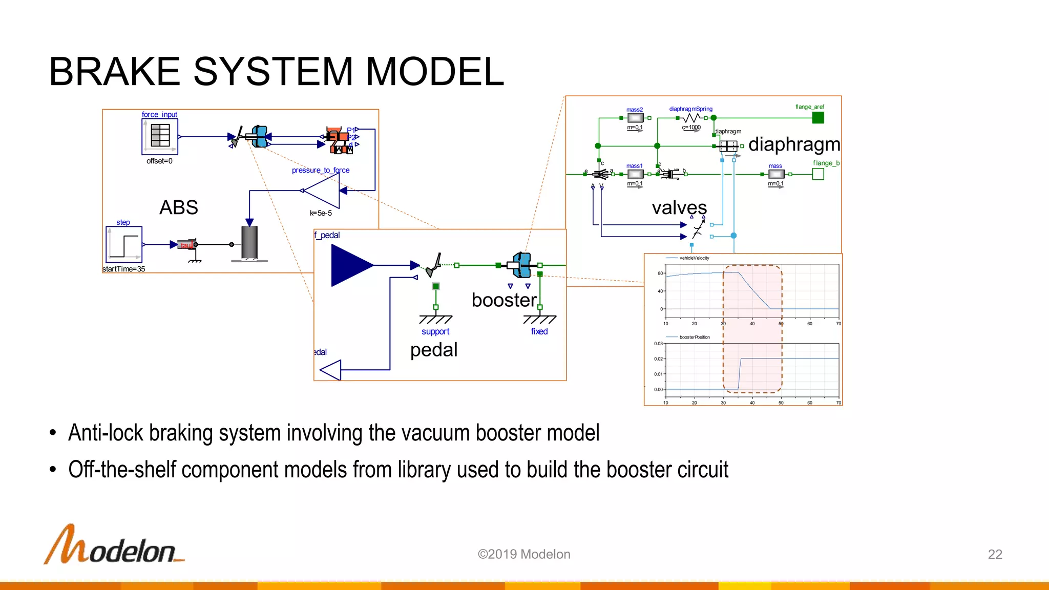


The pneumatics library by Modelon is a Modelica library designed for modeling pneumatic systems and circuits, based on ideal gas laws. It features a wide range of components for both mobile and stationary applications, enabling users to simulate, validate, and optimize pneumatic system designs across various industries. The library is compatible with other Modelon libraries and includes examples such as motor control and brake systems, emphasizing its versatility and ease-of-use for complex pneumatic modeling.