Download to read offline
![Sudhananda Paul1.et al. Int. Journal of Engineering Research and Applications www.ijera.com
ISSN: 2248-9622, Vol. 6, Issue 4, (Part - 4) April 2016, pp.34-37
www.ijera.com 35|P a g e
the operators adjust the control valves so as to keep
the pressure within limits. This results in wastage of
energy at the valves. If switching of pumps is done
based on requirement of plants, this energy which is
being wasted can be saved.
C. Techno-economic feasibility study of
equipment-connected PF improving
capacitors:
The existing system in FACT looks
improvement of power factor from maximum
demand (MD) only. A techno-economic feasibility
study of equipment-connected pf improving
capacitor forms as the third objective of this project.
The feasibility study comprises two parts viz.
technical part for finding out the capacitance
required for bringing the pf to unity and the
economic evaluation part consisting of life cycle
cost analysis. If the future value of the initial
investment for the capacitor for better pf of the
motor is less than the sum of future returns by way
of energy saving, the investment is justified. Here,
the value of capacitance required for bringing the pf
of CT Fan to unity is found out by measuring the
various parameters like active power, present pf,
running current etc. The resultant saving in energy,
by running the motor at unity, is computed by
measuring the circuit resistances involved viz. cable
resistance, winding resistance, switch, fuse and
contactor resistances. The life cycle cost is then
calculated to find out whether the investment is
worth making.[2]
Size of capacitor
Size of capacitor connected to a motor should
be such that the capacitor current should not
exceed the no load current of the motor at
normal voltage. Otherwise dangerously high
voltages will be generated when motors may be
damaged because after disconnection of motor
from supply motor will be still revolving and
act as generator by self excitation.
capacitor connection
The connection of LT Capacitors to a direct
starting motor or to an induction motor with slip
rings and starting resistors involves no problems if
output does not exceed consumed no load power of
motor. But over voltages up to three times rated
voltage due to self excitation could occur if
switching from star to delta and a line is broken
before neutral , it may damage motor and capacitor.
The above difficulties are avoided if 6-terminal
capacitor is used and connected in a single phase so
that capacitor discharges across the motor winding
while it is disconnected from the line
Advantages of pf improvement :
i. KVA rating of the equipment is reduced.
ii. Smaller conductor size.
iii.Copper losses are reduced.
iv. Good voltage regulation
v. Reduction of electricity bill
D. Automation of operation of cooling water
facility using PLC:
Today, automation is moving rapidly
towards a true point of central control that resides in
the system operator's office. It is becoming
increasingly necessary for the system operators to
have fingertip control of the process. This has been
greatly fulfilled by the use of programmable
devices. Programmable devices eliminate the need
of complex components and discrete components.
They are also more reliable , cheaper and it can
withstand harsh factory environments, perhaps the
biggest advantage of programmable devices is that
their functions are easily changeable by merely
changing the program stored in them thereby
eliminating the need for replacing the whole system
. Additional changes can be made incrementally.
They also allow interaction with other systems and
since their outputs are digital, their working can be
easily monitored by computers. In world of
automation, the programmable logic controller has
become a standard for control. It now not only
replaces the earlier relay controls but has taken over
many additional control functions. PLCs are used to
synchronize the flow of inputs from sensors and
events with the flow of outputs to actuators and
events. This leads to precisely controlled actions
that permit a tight control of the process or machine
.This project is devoted to the principle upon which
PLCs operate.[3]](https://image.slidesharecdn.com/e0604043437-160728112120/75/Energy-Saving-and-Water-Cooling-Facility-in-an-Industry-Using-Prgrammable-Logic-Controller-2-2048.jpg)
![Sudhananda Paul1.et al. Int. Journal of Engineering Research and Applications www.ijera.com
ISSN: 2248-9622, Vol. 6, Issue 4, (Part - 4) April 2016, pp.34-37
www.ijera.com 36|P a g e
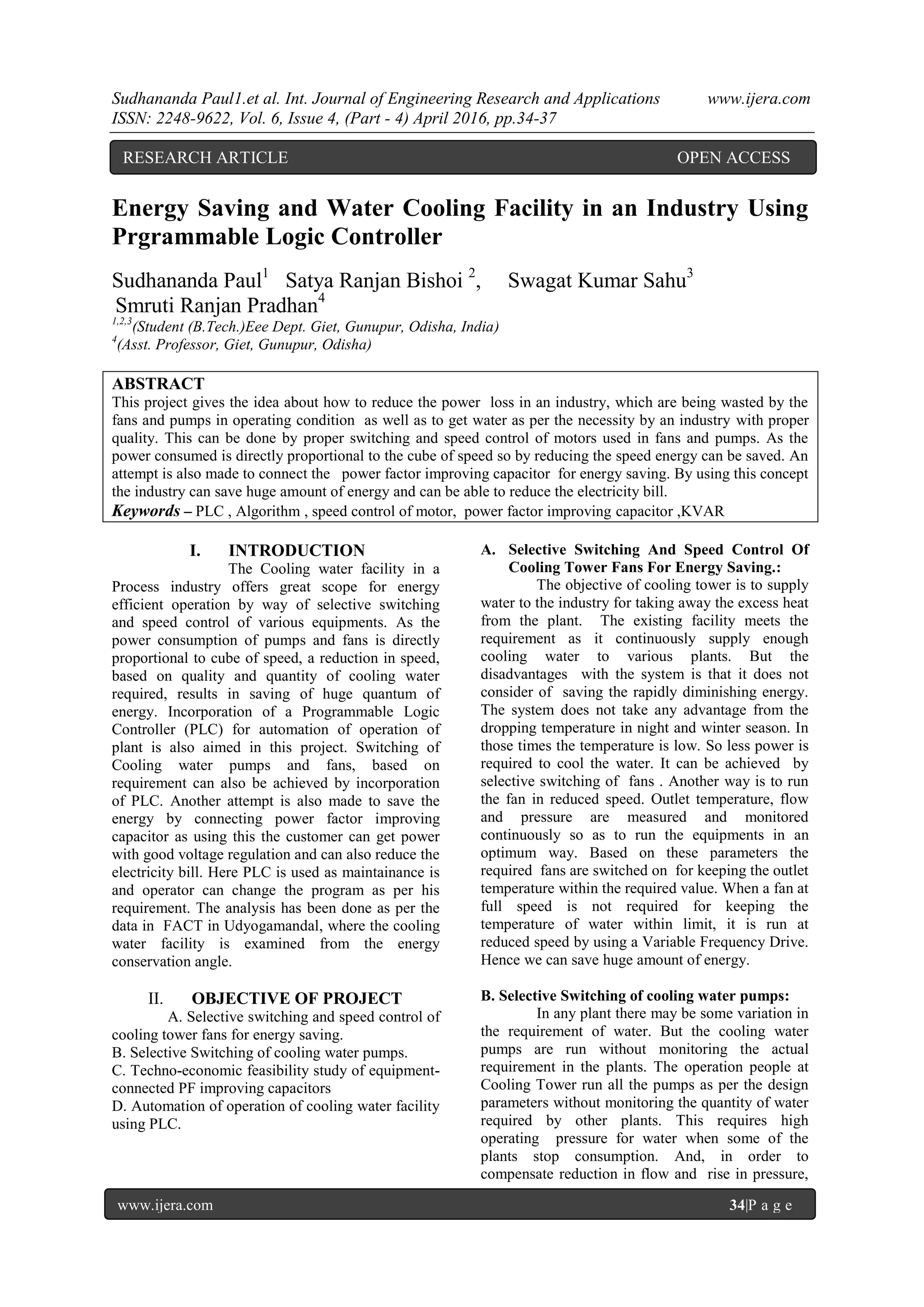
III. ALGORITHM USED
IV. ANALYSISANDINTERPRETATION
Capacitive kVAR to be added at the motor
terminals for improving the present pf of 0.76 to
unity is given by the formula;kVAR required
= kW (tan<D, - tan 02)
Where O] is the power factor angle before
correction and 02 is the power factor angle after
correction
Considering a pf correction to unity,
kVAR required= 38.47 (0.86 - 0)=33.08 kVAR
However, the maximum capacitive reactance that
can be added to the terminals of a
motor should not be more than its no-load reactance.
In this case: No-load kVA of the motor= 1.732 *
425.7 *30/1000= 22.00 kVAR
The various parameters of the fan, after connecting a
capacitive reactance of 22.00 kVAR will be:
Active power=38.47kW
Reactive power = 40.54 - 22.00 = 18.54kVAR
Apparent power=42.6 kVA
Current drawn by the motor= 55 A
Reduction in current=35A
Power dissipation in cable for a current of 35
A35A
2*0.154 * 3= 565.9 W
Energy consumption considering 330 days of
operation for fan= 565.9 *24 * 330 = 4482.3 kWh
Considering an energy cost of Rs.2.88/ kWh; total
amount for one year
= 4482.3 * 2.88 = Rs. 12,909/-
Cost of capacitor (22 kVAR)= Rs.25,000/-
A. Economic evaluation of investment Return
on investment method :
By evaluating the net present value of the total
cash flows, decision can be made whether the
investment is economical or not. A positive net
present value indicates a good investment, and a
negative net present value indicates a bad
investment.
Net Present Value (NPV) is given by the
formula
CFO + CF1/(1+K) + CF2/(1+K)2
+ CF3/(1+K)3
+
CF4/91+K)4
+ CF5/(1+K)5
+ CF6/(1+K)6
+
CF7/(1+K)7
+ CF8/(1+K)8
+ CF9/(1+K)9
+
CF10/(1+K)10
= 0
Where CFn is the cash flow in each year.
Negative sign is given to indicate cash outflow and
positive sign is given for cash inflow (saving). K is
the discount factor.
B. A
ssumptions:
Cost of energy increases by 10% once in
every 3 years
Discount rate k is taken as 12%
NPV = - 25000 + 79,820 = + 54,820. As NPV is a
high positive value, this indicates that it will be an
economical investment.](https://image.slidesharecdn.com/e0604043437-160728112120/75/Energy-Saving-and-Water-Cooling-Facility-in-an-Industry-Using-Prgrammable-Logic-Controller-3-2048.jpg)
![Sudhananda Paul1.et al. Int. Journal of Engineering Research and Applications www.ijera.com
ISSN: 2248-9622, Vol. 6, Issue 4, (Part - 4) April 2016, pp.34-37
www.ijera.com 37|P a g e
V. BENEFITS
i. More amount of energy can be saved.
ii. Water can be provided to the industry with
proper quantity and quality.
iii. As plc is used it is easy to operate
iv. Maintainance is easy.
v. Operator can change the program as per the
requirement
VI. CONCLUSION
This project titled ' energy saving and water
cooling facility in an industry using plc’ is a
combination of software programming and hardware
interfacing circuit designed for the automatic control
and power saving of the cooling water in FACT.
Our proposed system uses programmable logic
controllers and variable frequency drives. Techno
economical analysis shows that there could be a
greater improvement in the power consumption and
also in expenditure.
REFERENCE
[1]. Automating Manufacturing systems with
PLCs _
[2]. Hugh Jack
Cooling tower design data sheets,
petrochemical
[3]. division, FACT
[4]. Omron PLC manual
[5]. www.industrialtext.com
www.trilogic_plc.com](https://image.slidesharecdn.com/e0604043437-160728112120/75/Energy-Saving-and-Water-Cooling-Facility-in-an-Industry-Using-Prgrammable-Logic-Controller-4-2048.jpg)

This project focuses on reducing energy loss in industrial cooling systems through programmable logic controllers (PLCs) and speed control of motors for fans and pumps, which can save significant energy and reduce electricity bills. By implementing selective switching and monitoring water requirements, the system can optimize energy use and maintain proper water quality. The economic analysis indicates a positive return on investment, making the implementation feasible and beneficial for industries.


![Automatic power factor_improvement_and_monitoring_by_using_plc[1]](https://cdn.slidesharecdn.com/ss_thumbnails/automaticpowerfactorimprovementandmonitoringbyusingplc1-190905054934-thumbnail.jpg?width=640&height=640&fit=bounds)