Downloaded 752 times
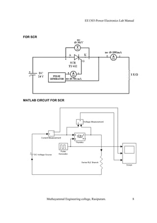
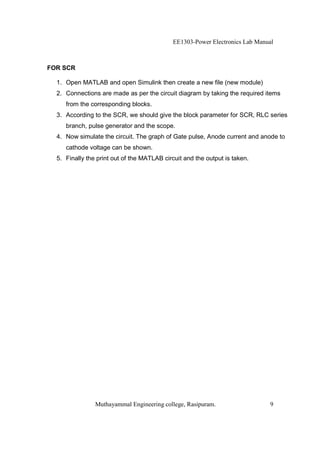
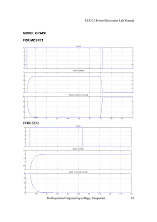
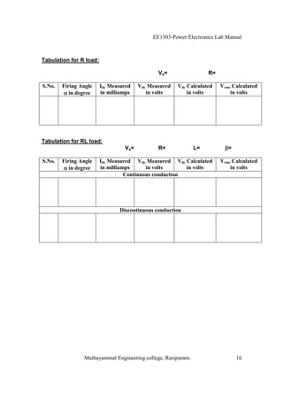
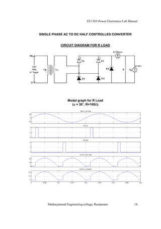
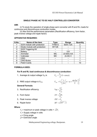
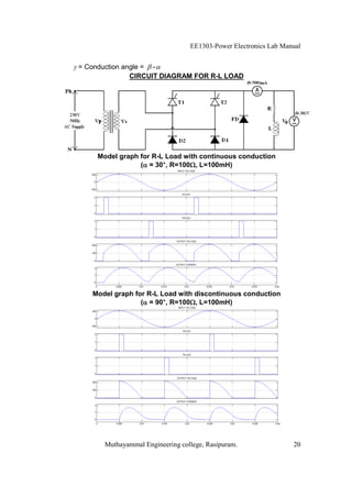


The EE1303 Power Electronics Lab Manual from Muthayammal Engineering College provides detailed instructions for conducting various experiments in power electronics, emphasizing safety protocols, attendance, and record-keeping. It outlines multiple experiments, including the characteristics of different semiconductor devices like SCRs and MOSFETs, and the operations of AC to DC converters, both fully and half-controlled. Each experiment includes aims, required apparatus, procedures, and formulas for analyzing electrical characteristics and performance parameters.


![Fundamentals of power electronics [presentation slides] 2nd ed r. erickson ww](https://cdn.slidesharecdn.com/ss_thumbnails/fundamentalsofpowerelectronicspresentationslides2nded-r-ericksonww-100522135011-phpapp02-thumbnail.jpg?width=640&height=640&fit=bounds)


