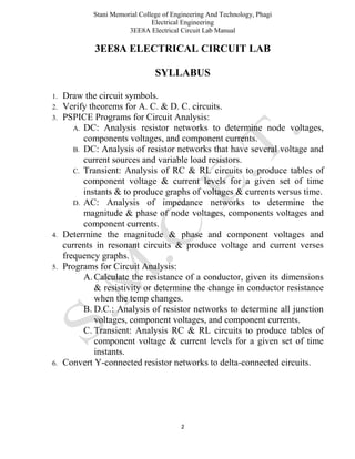
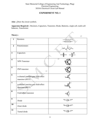
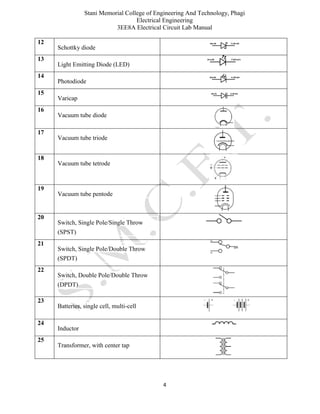
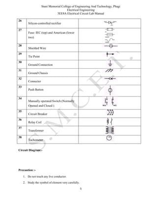
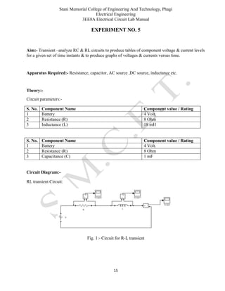
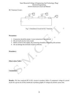
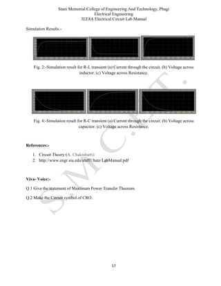
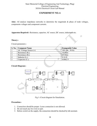
Stani Memorial College of Engineering And Technology, Phagi
Electrical Engineering
3EE8A Electrical Circuit Lab Manual
1
LAB MANUAL
Subject Code: 3EE8A
ELECTRICAL CIRCUIT LAB
(II B. Tech III Semester EE)
Established in year 2000
DEPARTMENT OF ELECTRICAL ENGINEERING
STANI MEMORIAL COLLEGE OF ENGINEERING & TECHNOLOGY,
PHAGI, JAIPUR – 303005
Website: www.smcet.in
Stani Memorial College of Engineering And Technology, Phagi
Electrical Engineering
3EE8A Electrical Circuit Lab Manual
2
3EE8A ELECTRICAL CIRCUIT LAB
SYLLABUS
1. Draw the circuit symbols.
2. Verify theorems for A. C. & D. C. circuits.
3. PSPICE Programs for Circuit Analysis:
A. DC: Analysis resistor networks to determine node voltages,
components voltages, and component currents.
B. DC: Analysis of resistor networks that have several voltage and
current sources and variable load resistors.
C. Transient: Analysis of RC & RL circuits to produce tables of
component voltage & current levels for a given set of time
instants & to produce graphs of voltages & currents versus time.
D. AC: Analysis of impedance networks to determine the
magnitude & phase of node voltages, components voltages and
component currents.
4. Determine the magnitude & phase and component voltages and
currents in resonant circuits & produce voltage and current verses
frequency graphs.
5. Programs for Circuit Analysis:
A. Calculate the resistance of a conductor, given its dimensions
& resistivity or determine the change in conductor resistance
when the temp changes.
B. D.C.: Analysis of resistor networks to determine all junction
voltages, component voltages, and component currents.
C. Transient: Analysis RC & RL circuits to produce tables of
component voltage & current levels for a given set of time
instants.
6. Convert Y-connected resistor networks to delta-connected circuits.
Stani Memorial College of Engineering And Technology, Phagi
Electrical Engineering
3EE8A Electrical Circuit Lab Manual
3
EXPERIMENT NO. 1
Aim: - Draw the circuit symbols.
Apparatus Required: - Resistors, Capacitors, Transistor, Diode, Batteries, single cell, multi-cell
Inductor, Transformer
Theory:-
1 Resistors
2 Potentiometer:
3 Capacitors
4
NPN Transistor
5
PNP transistor
6
n-channel junction gate field-effect
transistor (JFET)
7
p-channel junction gate field-effect
transistor (JFET)
8
Field-effect transistor
9
Diode
10
Zener diode
11
Tunnel diode
Stani Memorial College of Engineering And Technology, Phagi
Electrical Engineering
3EE8A Electrical Circuit Lab Manual
4
12
Schottky diode
13
Light Emitting Diode (LED)
14
Photodiode
15
Varicap
16
Vacuum tube diode
17
Vacuum tube triode
18
Vacuum tube tetrode
19
Vacuum tube pentode
20
Switch, Single Pole/Single Throw
(SPST)
21
Switch, Single Pole/Double Throw
(SPDT)
22
Switch, Double Pole/Double Throw
(DPDT)
23
Batteries, single cell, multi-cell
24
Inductor
25
Transformer, with center tap
Stani Memorial College of Engineering And Technology, Phagi
Electrical Engineering
3EE8A Electrical Circuit Lab Manual
5
26
Silicon-controlled rectifier
27
Fuse: IEC (top) and American (lower
two)
28
Shielded Wire
29
Tie Point
30
Ground Connection
31
Ground Chassis
32
Connecter
33
Push Button
34
Manually operated Switch (Normally
Opened and Closed )
35
Circuit Breaker
36
Relay Coil
37
Transformer
38
Tachometer
Circuit Diagram:-
Precaution :-
1. Do not touch any live conductor.
2. Study the symbol of element very carefully.
Stani Memorial College of Engineering And Technology, Phagi
Electrical Engineering
3EE8A Electrical Circuit Lab Manual
6
Procedure:-
Observation Table:-
Calculations:-
Result:- Drawing the circuit symbol has been done.
References:-
1. Circuit Theory (A. Chakrabarti)
2. http://www.allbookez.com/chakrabarti-circuit-theory/
Viva voice Question:-
Q.1 what is the role of transformer ?
Q.2 which quantity is measured by Tachometer?
Stani Memorial College of Engineering And Technology, Phagi
Electrical Engineering
3EE8A Electrical Circuit Lab Manual
7
EXPERIMENT NO. 2
Aim:- Verify theorems for A. C. & D. C. circuits.
Apparatus Required:- Resistance, capacitor, AC source ,DC source, inductance etc.
Theory:-
Circuit Diagram:-
1. Simulation for DC Theorems:-
Fig. 1:- Simulation Diagram
Stani Memorial College of Engineering And Technology, Phagi
Electrical Engineering
3EE8A Electrical Circuit Lab Manual
8
2. Simulation for AC Theorem:-
Fig 2:-Circuit diagram for Simulation.
Precaution:-
1. Connection should be proper. Loose connection is not allowed.
2. Do not touch any live wire or part.
3. Before switch on the supply, the connection should be checked by lab assistant.
4. Do not damage the terminals of part or wire etc.
Procedure:-
Observation Table:-
Observation Table I:-
S. No. Component Name Component Value
1 DC Volt. Source (V) 100 Volt.
2 Resistance (R1) 10 Ohm
3 Resistance (R2) 30 Ohm
4 Resistance (R3) 12 Ohm
5 Resistance (R4) 60 Ohm
Stani Memorial College of Engineering And Technology, Phagi
Electrical Engineering
3EE8A Electrical Circuit Lab Manual
9
Observation Table II:-
S. No. Compnent Name Component Value
1 AC Voltage Source (v) 100 volt., 50 Hz.
2 Resistance (R1) 10 Ohm
3 Resistance (R2) 12 Ohm
4 Inductor (L1) 0.16 H
5 Capaciter (C1) 0.0062 F
Result:- We have successfully Verified theorems for A. C. & D. C. circuits.
Simulation Results:-
S. No. Component Name Volt. Drop Current
1 Resistance (R1) 28.81 Volt. 2.881 Amp.
2 Resistance (R2) 50.85 Volt. 1.695 Amp.
3 Resistance (R3) 20.34 Volt. 1.695 Amp.
4 Resistance (R4) 71.19 Volt. 1.186 Amp.
Fig.3: (a) Volt. and Current in Resistance R1, (b) Volt. and Current in Inductor L1.
Fig. 4: (a) Volt. and Current in Resistance R2 (b) Volt. and Current in Capacitor C1.
Stani Memorial College of Engineering And Technology, Phagi
Electrical Engineering
3EE8A Electrical Circuit Lab Manual
10
References:-
1. Circuit Theory (A. Chakrabarti)
2. http://www.engr.siu.edu/staff1/hatz/ECE235/ECE235LabManual.pdf
Viva voice Question:-
Q. 1 Give the statement of Superposition Theorem.
Q. 2 State the Nortan Theorems.
Stani Memorial College of Engineering And Technology, Phagi
Electrical Engineering
3EE8A Electrical Circuit Lab Manual
11
EXPERIMENT NO. 3
Aim:- DC-analyze resistor networks to determine node voltages, components voltages, and
component currents.
Apparatus Required:- Resistance, capacitor, AC source ,DC source, inductance etc.
Theory:-
Circuit Parameter:-
S. No. Component Name Component Value
1 DC Volt. Source (V) 100 Volt.
2 Resistance (R1) 10 Ohm
3 Resistance (R2) 30 Ohm
4 Resistance (R3) 12 Ohm
5 Resistance (R4) 60 Ohm
Circuit Diagram:-
Fig. 1:- Simulation Diagram
Precaution:-
1. Connection should be proper. Loose connection is not allowed.
2. Do not touch any live wire or part.
Stani Memorial College of Engineering And Technology, Phagi
Electrical Engineering
3EE8A Electrical Circuit Lab Manual
12
3. Before switch on the supply, the connection should be checked by lab assistant.
4. Do not damage the terminals of part or wire etc.
Procedure:-
Observation Table:-
Calculations:-
Results:-
Simulation Results:-
S. No. Component Name Volt. Drop Current
1 Resistance (R1) 28.81 Volt. 2.881 Amp.
2 Resistance (R2) 50.85 Volt. 1.695 Amp.
3 Resistance (R3) 20.34 Volt. 1.695 Amp.
4 Resistance (R4) 71.19 Volt. 1.186 Amp.
References:-
1. Circuit Theory (A. Chakrabarti)
2. http://www.engr.siu.edu/staff1/hatz/ECE235/ECE235LabManual.pdf
Viva- Voice:-
Q.1 Give the statement of KVL.
Q.2 Make the circuit symbol of Zener Diode.
Stani Memorial College of Engineering And Technology, Phagi
Electrical Engineering
3EE8A Electrical Circuit Lab Manual
13
EXPERIMENT NO. 4
Aim:- Analyze resistor networks that have several voltage and current sources and variable load
resistors.
Apparatus Required:- Resistance, capacitor, AC source ,DC source, inductance etc.
Theory:-
Circuit Parameters:-
S. No Component Component Value
1 Voltage Source (V1) 20 Volt.
2 Voltage Source (V2) 10 Volt.
3 Voltage Source (V3) 100 Amp.
4 Current Source (I1) 2 Amp.
5 Current Source (I2) 1 Amp.
6 Resistance (R1) 6 Ohm
7 Resistance (R2) 5 Ohm
8 Resistance (R3) 12 Ohm
9 Resistance (R4) 2 Ohm
10 Resistance (R5) 10 Ohm
11 Resistance (R6) 30 Ohm
12 Resistance (R7) 20 Ohm
13 Resistance (RL) 10 Ohm
Circuit Diagram:-
Fig.1:-Simulation diagram of the circuit
Stani Memorial College of Engineering And Technology, Phagi
Electrical Engineering
3EE8A Electrical Circuit Lab Manual
14
Precaution:-
1. Connection should be proper. Loose connection is not allowed.
2. Do not touch any live wire or part.
3. Before switch on the supply, the connection should be checked by lab assistant.
4. Do not damage the terminals of part or wire etc.
Procedure:-
Observation Table:-
Calculations:-
Results:- We have performed the experiment and obtained load current value 1.355.
References:-
1. Circuit Theory (A. Chakrabarti)
2. http://www.engr.siu.edu/staff1/hatz/ECE235/ECE235LabManual.pdf
Viva- Voice:-
Q.1 Give the statement of KCL.
Q.2 Make the Circuit symbol of Variable capacitance.
Stani Memorial College of Engineering And Technology, Phagi
Electrical Engineering
3EE8A Electrical Circuit Lab Manual
15
EXPERIMENT NO. 5
Aim:- Transient –analyze RC & RL circuits to produce tables of component voltage & current levels
for a given set of time instants & to produce graphs of voltages & currents versus time.
Apparatus Required:- Resistance, capacitor, AC source ,DC source, inductance etc.
Theory:-
Circuit parameters:-
S. No. Component Name Component value / Rating
1 Battery 4 Volt.
2 Resistance (R) 8 Ohm
3 Inductance (L) 18 mH
S. No. Component Name Component value / Rating
1 Battery 4 Volt.
2 Resistance (R) 8 Ohm
3 Capacitance (C) 1 mF
Circuit Diagram:-
RL transient Circuit:
Fig. 1:- Circuit for R-L transient
Stani Memorial College of Engineering And Technology, Phagi
Electrical Engineering
3EE8A Electrical Circuit Lab Manual
16
RC Transient Circuit:-
Fig. 3: Simulation Circuit for R-C Transient.
Precaution:-
1. Connection should be proper. Loose connection is not allowed.
2. Do not touch any live wire or part.
3. Before switch on the supply, the connection should be checked by lab assistant.
4. Do not damage the terminals of part or wire etc.
Procedure:-
Observation Table:-
Calculations:-
Results:- We have analyzed RC & RL circuits to produce tables of component voltage & current
levels for a given set of time instants & to produce graphs of voltages & currents versus time.
Stani Memorial College of Engineering And Technology, Phagi
Electrical Engineering
3EE8A Electrical Circuit Lab Manual
17
Simulation Results:-
Fig. 2:-Simulation result for R-L transient (a) Current through the circuit. (b) Voltage across
inductor. (c) Voltage across Resistance.
Fig. 4:-Simulation result for R-C transient (a) Current through the circuit. (b) Voltage across
capacitor. (c) Voltage across Resistance.
References:-
1. Circuit Theory (A. Chakrabarti)
2. http://www.engr.siu.edu/staff1/hatz/LabManual.pdf
Viva- Voice:-
Q.1 Give the statement of Maximum Power Transfer Theorem.
Q.2 Make the Circuit symbol of CRO.
Stani Memorial College of Engineering And Technology, Phagi
Electrical Engineering
3EE8A Electrical Circuit Lab Manual
18
EXPERIMENT NO. 6
Aim:- AC-analyze impedance networks to determine the magnitude & phase of node voltages,
components voltages and component currents.
Apparatus Required:- Resistance, capacitor, AC source ,DC source, inductance etc.
Theory:-
Circuit parameters:-
S. No. Compnent Name Component Value
1 AC Voltage Source (v) 100 volt., 50 Hz.
2 Resistance (R1) 10 Ohm
3 Resistance (R2) 12 Ohm
4 Inductor (L1) 0.16 H
5 Capaciter (C1) 0.0062 F
Circuit Diagram:-
Fig 1:-Circuit diagram for Simuliation.
Precaution:-
1. Connection should be proper. Loose connection is not allowed.
2. Do not touch any live wire or part.
3. Before switch on the supply, the connection should be checked by lab assistant.
Stani Memorial College of Engineering And Technology, Phagi
Electrical Engineering
3EE8A Electrical Circuit Lab Manual
19
4. Do not damage the terminals of part or wire etc.
Procedure:-
Observation Table:-
Calculations:-
Results:- We have analyzed impedance networks to determine the magnitude & phase of node
voltages, components voltages and component currents
Simulation Results:-
Fig. 2: (a) Volt. and Current in Resistance R1, (b) Volt. and Current in Inductor L1.
Fig. 3: (a) Volt. and Current in Resistance R2 (b) Volt. and Current in Capacitor C1.
Stani Memorial College of Engineering And Technology, Phagi
Electrical Engineering
3EE8A Electrical Circuit Lab Manual
20
References:-
1. Circuit Theory (A. Chakrabarti)
2. Hayt&Kemmerly, “Engineeirng Circuit Analysis”, 6/e (TMH)
Viva- Voice:-
Q.1 Give the statement of Maximum Power Transfer Theorem.
Q.2 Make the Circuit symbol of CRO.
Stani Memorial College of Engineering And Technology, Phagi
Electrical Engineering
3EE8A Electrical Circuit Lab Manual
21
EXPERIMENT NO. 7
Aim:- Determine the magnitude & phase and component voltages and currents in resonant circuits &
produce voltage and current v/s frequency graphs.
Apparatus Required:- Resistance, capacitor, AC source ,DC source, inductance etc.
Theory:-
Circuit parameters:-
S. No Component Component Value
1 Source Voltage 230
2 Resistance (R) 60 Ohm
3 Inductance (L) 0.01 H
4 Capacitance (C) 0.0010 F
Circuit Diagram:-
Fig.1:-Simulation diagram of the circuit.
Precaution:-
1. Connection should be proper. Loose connection is not allowed.
2. Do not touch any live wire or part.
3. Before switch on the supply, the connection should be checked by lab assistant.
Stani Memorial College of Engineering And Technology, Phagi
Electrical Engineering
3EE8A Electrical Circuit Lab Manual
22
4. Do not damage the terminals of part or wire etc.
Procedure:-
Observation Table:-
Calculations:-
Results:- We have Determined the magnitude & phase and component voltages and currents in
resonant circuits & produce voltage and current v/s frequency graphs.
Fig 2:- Output of vl and vc ((output of scope).
Fig. 3:- Current in circuit (output of scope1).
Stani Memorial College of Engineering And Technology, Phagi
Electrical Engineering
3EE8A Electrical Circuit Lab Manual
23
Fig 4:- Volt across resistance (output of scope 2).
References:-
1. Circuit Theory (A. Chakrabarti)
2. http://www.engr.siu.edu/staff1/hatz/LabManual.pdf
Viva- Voice:-
Q.1 Give the statement of Maxwell Theorem.
Q.2 Make the Circuit symbol of Diode.
Stani Memorial College of Engineering And Technology, Phagi
Electrical Engineering
3EE8A Electrical Circuit Lab Manual
24
EXPERIMENT NO. 8
Aim:- Calculate the resistance of a conductor given it’s dimension and resistivity, also determine the
change in conductor when the temp. changes.
Apparatus Required:- Power supply, Turbo C++.
Theory:-
Program:-
%Calculate the resistance of a conductor given it’s dimension and
%resistivity, also determine the change in conductor when the temp.
%changes.
clc
clear
ch=1;
while (ch==1)
disp('1 if Resistivity, length, Cross Section Area is Given and 2 if Temp.')
disp(' coefficient, Old Temp. Resistance, Temp Difference given')
choice=input('Enter your choice: ');
switch (choice)
case 1
ro = input('Enter the value of conductor resistivity(in ohm/m^2): ');
l = input('enter the value of length (in meter): ');
A = input('enter the value of area (in meter^2): ');
R = ro*l*A
ch=input('If You want to calculate more, than enter 1 else 2 ');
case 2
t1 = input('enter value of initial temperature(in degree celcious): ');
t2 = input('enter value of final temperature (in degree celcious): ');
t = t2 - t1;
r1 = input('resistance at temp. t1 (in ohm): ');
a= input('enter value of temperature co-efficient: ');
disp('resistance at t2 (in ohm): ')
R2 = r1*(1+(a*t))
ch=input('If You want to calculate more, than enter 1 else 2 ');
otherwise
disp('Incorrect input argument, to find parameter please run program again')
disp('Thanks Program by ASHOK KUMAR')
ch=input('If You want to calculate more, than enter 1 else 2 ');
end
end
Stani Memorial College of Engineering And Technology, Phagi
Electrical Engineering
3EE8A Electrical Circuit Lab Manual
25
Circuit Diagram:-
Precaution:-
1. Do not tamper with software settings.
Procedure:-
Observation Table:-
Calculations:-
Results:-
Output
1 if Resistivity, length, Cross Section Area is Given and 2 if Temp.
coefficient, Old Temp. Resistance, Temp Difference given
Enter your choice: 1
Enter the value of conductor resistivity(in ohm/m^2): 0.00043
enter the value of length (in meter): 2
enter the value of area (in meter^2): 5
R =
Stani Memorial College of Engineering And Technology, Phagi
Electrical Engineering
3EE8A Electrical Circuit Lab Manual
26
0.0043
If You want to calculate more, than enter 1 else 2 1
1 if Resistivity, length, Cross Section Area is Given and 2 if Temp.
cofficient, Old Temp. Resistance, Temp Difference given
Enter your choice: 2
enter value of initial temperature(in degree celcious): 37
enter value of final temperature (in degree celcious): 54
resistance at temp. t1 (in ohm): 2
enter value of temperature co-efficient: 3
resistance at t2 (in ohm):
R2 =
104
If You want to calculate more, than enter 1 else 2 2
>>
References:-
1. Circuit Theory (A. Chakrabarti)
Viva- Voice:-
Q.1 what is dependency of temp on the resistance?
Q.2 Make the Circuit symbol of Temp Dependent Resistance.
Stani Memorial College of Engineering And Technology, Phagi
Electrical Engineering
3EE8A Electrical Circuit Lab Manual
27
EXPERIMENT NO. 9
Aim :- D.C.-analyze resistor networks to determine all junction voltages, component voltages, and
component currents.
Apparatus Required:- Power supply, Turbo C++.
Theory:-
Program:-
%This Program calculate:-
%D.C.-analyze resistor networks to determine all junction voltages,
%component voltages, and component currents.
clc
clear
% First Input all circuit papameters
V=input('Enter the value of source voltage (In Volt.) = ');
R1=input('Enter the value of Resistance R1 (In Ohm)) = ');
R2=input('Enter the value of Resistance R2 (In Ohm)) = ');
R3=input('Enter the value of Resistance R3 (In Ohm)) = ');
R4=input('Enter the value of Resistance R4 (In Ohm)) = ');
%Now total current I in the circuit will be given by I=V/Req
%and Req is given by Req=(R1+(R4*(R2+R3))/(R2+R3+R4))
Req=(R1+(R4*(R2+R3))/(R2+R3+R4));
I=V/Req;
% From Current division rule current in R2 will be given by
%I2=I*R4/(R2+R3+R4)
I2=I*R4/(R2+R3+R4);
% From Current division rule current in R2 will be given by
%I2=I*(R2+R3)/(R2+R3+R4)
I3=I*(R2+R3)/(R2+R3+R4);
%Now Display all quantity
disp('Current through R1 is'), I
disp('Voltage across R1 is '), V1=I*R1
disp('Current through R2 is'), I2
disp('Voltage across R2 is '), V2=I2*R2
disp('Current through R3 is'), I2
disp('Voltage across R3 is '), V3=I2*R3
disp('Current through R4 is'), I3
disp('Voltage across R4 is '), V4=I3*R4
disp('Node Voltage Vnode is '),Vnode=V4
Stani Memorial College of Engineering And Technology, Phagi
Electrical Engineering
3EE8A Electrical Circuit Lab Manual
28
Circuit Diagram:-
Fig 1:-Reference Circuit for the program.
Precaution:-
1. Do not tamper with software settings.
Procedure:-
Observation Table:-
Calculations:-
Results:-
Enter the value of source voltage (In Volt.) = 100
Enter the value of Resistance R1 (In Ohm)) = 10
Enter the value of Resistance R2 (In Ohm)) = 30
Enter the value of Resistance R3 (In Ohm)) = 12
Enter the value of Resistance R4 (In Ohm)) = 60
Stani Memorial College of Engineering And Technology, Phagi
Electrical Engineering
3EE8A Electrical Circuit Lab Manual
29
Current through R1 is
I =
2.8814
Voltage across R1 is
V1 =
28.8136
Current through R2 is
I2 =
1.6949
Voltage across R2 is
V2 =
50.8475
Current through R3 is
I2 =
1.6949
Voltage across R3 is
V3 =
20.3390
Current through R4 is
I3 =
1.1864
Voltage across R4 is
V4 =
71.1864
Node Voltage Vnode is
Stani Memorial College of Engineering And Technology, Phagi
Electrical Engineering
3EE8A Electrical Circuit Lab Manual
30
Vnode =
71.1864
>>
References:-
1. Circuit Theory (A. Chakrabarti)
Viva- Voice:-
Q.1 what is Junction Voltage?
Q.2 Make the Circuit symbol of dependent voltage source.
Stani Memorial College of Engineering And Technology, Phagi
Electrical Engineering
3EE8A Electrical Circuit Lab Manual
31
EXPERIMENT NO. 10
Aim:- Transient analysis RC & RL ckts to produce table of component volts and current levels for
given set of your time interval.
Apparatus Required:- Power supply, Turbo C++.
Theory:-
Program:-
%Transient analysis RC & RL ckts to produce table of component volts and
%current levels for given set of your time interval.
clc
clear
ch=1;
while (ch==1)
disp('Enter 1 for R-L ckt or 2 for R-C ckt.')
choice=input('Enter your choice: ');
switch (choice)
case 1
disp('Please enter circuit parameter for Series R-L circuit: ')
R=input('Enter the value of circuit Resistance R (in Ohm): ');
L=input('Enter the value of circuit Inductance L (in Henery): ');
V=input('Enter the value of circuit Voltage V (in Volts.): ');
t=input('Enter the value of Time t (in sec): ');
I=(V/R)*(1-exp(-R*t/L))
VR=I*R
VL=V-VR
ch=input('If You want to calculate more, than enter 1 else 2 ');
case 2
disp('Please enter circuit parameter for Series R-C circuit: ')
R=input('Enter the value of circuit Resistance R (in Ohm): ');
C=input('Enter the value of circuit Inductance C (in Farad): ');
V=input('Enter the value of circuit Voltage V (in Volts.): ');
t=input('Enter the value of Time t (in sec): ');
I=(V/R)*(1-exp(-R*t*C))
VR=I*R
VC=V-VR
ch=input('If You want to calculate more, than enter 1 else 2 ');
otherwise
disp('Incorrect input argument, to find parameter please run program again')
disp('Thanks Program by ASHOK KUMAR')
ch=input('If You want to calculate more, than enter 1 else 2 ');
Stani Memorial College of Engineering And Technology, Phagi
Electrical Engineering
3EE8A Electrical Circuit Lab Manual
32
end
end
disp('Thanks Program by XYZ')
Circuit Diagram:-
Precaution:-
1. Do not tamper with software settings.
Procedure:-
Observation Table:-
Calculations:-
Result:-
Enter 1 for R-L ckt or 2 for R-C ckt.
Enter your choice: 1
Please enter circuit parameter for Series R-L circuit:
Enter the value of circuit Resistance R (in Ohm): 10
Enter the value of circuit Inductance L (in Henery): .018
Enter the value of circuit Voltage V (in Volts.): 50
Stani Memorial College of Engineering And Technology, Phagi
Electrical Engineering
3EE8A Electrical Circuit Lab Manual
33
Enter the value of Time t (in sec): .0032
I =
4.1549
VR =
41.5493
VL =
8.4507
If You want to calculate more, than enter 1 else 2 1
Enter 1 for R-L ckt or 2 for R-C ckt.
Enter your choice: 2
Please enter circuit parameter for Series R-C circuit:
Enter the value of circuit Resistance R (in Ohm): 10
Enter the value of circuit Inductance C (in Farad): .018
Enter the value of circuit Voltage V (in Volts.): 50
Enter the value of Time t (in sec): .0032
I =
0.0029
VR =
0.0288
VC =
49.9712
If You want to calculate more, than enter 1 else 2 2
disp('Thanks Program by XYZ)
>>
Stani Memorial College of Engineering And Technology, Phagi
Electrical Engineering
3EE8A Electrical Circuit Lab Manual
34
References:-
1. Circuit Theory (A. Chakrabarti)
Viva- Voice:-
Q.1 value of internal resistance of idea voltage source?
Q.2 Make the Circuit symbol of independent voltage source.
Stani Memorial College of Engineering And Technology, Phagi
Electrical Engineering
3EE8A Electrical Circuit Lab Manual
35
EXPERIMENT NO. 11
Aim:- Convert Y-connected resistor networks to delta-connected circuits.
Apparatus Required:- Power supply, Turbo C++.
Theory:-
Program:-
clc
clear
ch=1;
while (ch==1)
choice=input('Enter your choice: 1 for Y-D and 2 for D-Y Transformation ');
switch (choice)
case 1
R1=input('Enter the value of resistance 1 ');
R2=input('Enter the value of resistance 2 ');
R3=input('Enter the value of resistance 3 ');
R12=(R1*R2)/(R1+R2+R3)
R23=(R2*R3)/(R1+R2+R3)
R31=(R3*R1)/(R1+R2+R3)
disp('Thanks Program by ASHOK KUMAR')
ch=input('If You want to calculate more, than enter 1 else 2 ');
case 2
R12=input('Enter the value of resistance 12 ');
R23=input('Enter the value of resistance 23 ');
R31=input('Enter the value of resistance 31 ');
R1=(R12*R23+R23*R31+R31*R23)/R23
R2=(R12*R23+R23*R31+R31*R23)/R31
R3=(R12*R23+R23*R31+R31*R23)/R12
disp('Thanks Program by XYZ)
ch=input('If You want to calculate more, than enter 1 else 2 ');
otherwise
disp('Incorrect input argument, to find parameter please run program again')
disp('Thanks Program by XYZ)
ch=input('If You want to calculate more, than enter 1 else 2 ');
end
end
Stani Memorial College of Engineering And Technology, Phagi
Electrical Engineering
3EE8A Electrical Circuit Lab Manual
36
Circuit Diagram:-
Precaution:-
1. Do not tamper with software settings.
Procedure:-
Observation Table:-
Calculations:-
Result:-
Enter your choice: 1 for Y-D and 2 for D-Y Transformation 1
Enter the value of resistance 1 4
Enter the value of resistance 2 4
Enter the value of resistance 3 4
R12 =
1.3333
R23 =
1.3333
R31 =
Stani Memorial College of Engineering And Technology, Phagi
Electrical Engineering
3EE8A Electrical Circuit Lab Manual
37
1.3333
Thanks Program by ASHOK KUMAR
If You want to calculate more, than enter 1 else 2 1
Enter your choice: 1 for Y-D and 2 for D-Y Transformation 2
Enter the value of resistance 12 4
Enter the value of resistance 23 4
Enter the value of resistance 31 4
R1 =
12
R2 =
12
R3 =
12
Thanks Program by XYZ
If You want to calculate more, than enter 1 else 2 2
References:-
1. Circuit Theory (A. Chakrabarti)
Viva- Voice:-
Q.1 value of internal resistance of idea current source?
Q.2 Make the Circuit symbol of independent current source.

Circuit Analysis Lab

  • 1.
    Stani Memorial Collegeof Engineering And Technology, Phagi Electrical Engineering 3EE8A Electrical Circuit Lab Manual 1 LAB MANUAL Subject Code: 3EE8A ELECTRICAL CIRCUIT LAB (II B. Tech III Semester EE) Established in year 2000 DEPARTMENT OF ELECTRICAL ENGINEERING STANI MEMORIAL COLLEGE OF ENGINEERING & TECHNOLOGY, PHAGI, JAIPUR – 303005 Website: www.smcet.in
  • 2.
    Stani Memorial Collegeof Engineering And Technology, Phagi Electrical Engineering 3EE8A Electrical Circuit Lab Manual 2 3EE8A ELECTRICAL CIRCUIT LAB SYLLABUS 1. Draw the circuit symbols. 2. Verify theorems for A. C. & D. C. circuits. 3. PSPICE Programs for Circuit Analysis: A. DC: Analysis resistor networks to determine node voltages, components voltages, and component currents. B. DC: Analysis of resistor networks that have several voltage and current sources and variable load resistors. C. Transient: Analysis of RC & RL circuits to produce tables of component voltage & current levels for a given set of time instants & to produce graphs of voltages & currents versus time. D. AC: Analysis of impedance networks to determine the magnitude & phase of node voltages, components voltages and component currents. 4. Determine the magnitude & phase and component voltages and currents in resonant circuits & produce voltage and current verses frequency graphs. 5. Programs for Circuit Analysis: A. Calculate the resistance of a conductor, given its dimensions & resistivity or determine the change in conductor resistance when the temp changes. B. D.C.: Analysis of resistor networks to determine all junction voltages, component voltages, and component currents. C. Transient: Analysis RC & RL circuits to produce tables of component voltage & current levels for a given set of time instants. 6. Convert Y-connected resistor networks to delta-connected circuits.
  • 3.
    Stani Memorial Collegeof Engineering And Technology, Phagi Electrical Engineering 3EE8A Electrical Circuit Lab Manual 3 EXPERIMENT NO. 1 Aim: - Draw the circuit symbols. Apparatus Required: - Resistors, Capacitors, Transistor, Diode, Batteries, single cell, multi-cell Inductor, Transformer Theory:- 1 Resistors 2 Potentiometer: 3 Capacitors 4 NPN Transistor 5 PNP transistor 6 n-channel junction gate field-effect transistor (JFET) 7 p-channel junction gate field-effect transistor (JFET) 8 Field-effect transistor 9 Diode 10 Zener diode 11 Tunnel diode
  • 4.
    Stani Memorial Collegeof Engineering And Technology, Phagi Electrical Engineering 3EE8A Electrical Circuit Lab Manual 4 12 Schottky diode 13 Light Emitting Diode (LED) 14 Photodiode 15 Varicap 16 Vacuum tube diode 17 Vacuum tube triode 18 Vacuum tube tetrode 19 Vacuum tube pentode 20 Switch, Single Pole/Single Throw (SPST) 21 Switch, Single Pole/Double Throw (SPDT) 22 Switch, Double Pole/Double Throw (DPDT) 23 Batteries, single cell, multi-cell 24 Inductor 25 Transformer, with center tap
  • 5.
    Stani Memorial Collegeof Engineering And Technology, Phagi Electrical Engineering 3EE8A Electrical Circuit Lab Manual 5 26 Silicon-controlled rectifier 27 Fuse: IEC (top) and American (lower two) 28 Shielded Wire 29 Tie Point 30 Ground Connection 31 Ground Chassis 32 Connecter 33 Push Button 34 Manually operated Switch (Normally Opened and Closed ) 35 Circuit Breaker 36 Relay Coil 37 Transformer 38 Tachometer Circuit Diagram:- Precaution :- 1. Do not touch any live conductor. 2. Study the symbol of element very carefully.
  • 6.
    Stani Memorial Collegeof Engineering And Technology, Phagi Electrical Engineering 3EE8A Electrical Circuit Lab Manual 6 Procedure:- Observation Table:- Calculations:- Result:- Drawing the circuit symbol has been done. References:- 1. Circuit Theory (A. Chakrabarti) 2. http://www.allbookez.com/chakrabarti-circuit-theory/ Viva voice Question:- Q.1 what is the role of transformer ? Q.2 which quantity is measured by Tachometer?
  • 7.
    Stani Memorial Collegeof Engineering And Technology, Phagi Electrical Engineering 3EE8A Electrical Circuit Lab Manual 7 EXPERIMENT NO. 2 Aim:- Verify theorems for A. C. & D. C. circuits. Apparatus Required:- Resistance, capacitor, AC source ,DC source, inductance etc. Theory:- Circuit Diagram:- 1. Simulation for DC Theorems:- Fig. 1:- Simulation Diagram
  • 8.
    Stani Memorial Collegeof Engineering And Technology, Phagi Electrical Engineering 3EE8A Electrical Circuit Lab Manual 8 2. Simulation for AC Theorem:- Fig 2:-Circuit diagram for Simulation. Precaution:- 1. Connection should be proper. Loose connection is not allowed. 2. Do not touch any live wire or part. 3. Before switch on the supply, the connection should be checked by lab assistant. 4. Do not damage the terminals of part or wire etc. Procedure:- Observation Table:- Observation Table I:- S. No. Component Name Component Value 1 DC Volt. Source (V) 100 Volt. 2 Resistance (R1) 10 Ohm 3 Resistance (R2) 30 Ohm 4 Resistance (R3) 12 Ohm 5 Resistance (R4) 60 Ohm
  • 9.
    Stani Memorial Collegeof Engineering And Technology, Phagi Electrical Engineering 3EE8A Electrical Circuit Lab Manual 9 Observation Table II:- S. No. Compnent Name Component Value 1 AC Voltage Source (v) 100 volt., 50 Hz. 2 Resistance (R1) 10 Ohm 3 Resistance (R2) 12 Ohm 4 Inductor (L1) 0.16 H 5 Capaciter (C1) 0.0062 F Result:- We have successfully Verified theorems for A. C. & D. C. circuits. Simulation Results:- S. No. Component Name Volt. Drop Current 1 Resistance (R1) 28.81 Volt. 2.881 Amp. 2 Resistance (R2) 50.85 Volt. 1.695 Amp. 3 Resistance (R3) 20.34 Volt. 1.695 Amp. 4 Resistance (R4) 71.19 Volt. 1.186 Amp. Fig.3: (a) Volt. and Current in Resistance R1, (b) Volt. and Current in Inductor L1. Fig. 4: (a) Volt. and Current in Resistance R2 (b) Volt. and Current in Capacitor C1.
  • 10.
    Stani Memorial Collegeof Engineering And Technology, Phagi Electrical Engineering 3EE8A Electrical Circuit Lab Manual 10 References:- 1. Circuit Theory (A. Chakrabarti) 2. http://www.engr.siu.edu/staff1/hatz/ECE235/ECE235LabManual.pdf Viva voice Question:- Q. 1 Give the statement of Superposition Theorem. Q. 2 State the Nortan Theorems.
  • 11.
    Stani Memorial Collegeof Engineering And Technology, Phagi Electrical Engineering 3EE8A Electrical Circuit Lab Manual 11 EXPERIMENT NO. 3 Aim:- DC-analyze resistor networks to determine node voltages, components voltages, and component currents. Apparatus Required:- Resistance, capacitor, AC source ,DC source, inductance etc. Theory:- Circuit Parameter:- S. No. Component Name Component Value 1 DC Volt. Source (V) 100 Volt. 2 Resistance (R1) 10 Ohm 3 Resistance (R2) 30 Ohm 4 Resistance (R3) 12 Ohm 5 Resistance (R4) 60 Ohm Circuit Diagram:- Fig. 1:- Simulation Diagram Precaution:- 1. Connection should be proper. Loose connection is not allowed. 2. Do not touch any live wire or part.
  • 12.
    Stani Memorial Collegeof Engineering And Technology, Phagi Electrical Engineering 3EE8A Electrical Circuit Lab Manual 12 3. Before switch on the supply, the connection should be checked by lab assistant. 4. Do not damage the terminals of part or wire etc. Procedure:- Observation Table:- Calculations:- Results:- Simulation Results:- S. No. Component Name Volt. Drop Current 1 Resistance (R1) 28.81 Volt. 2.881 Amp. 2 Resistance (R2) 50.85 Volt. 1.695 Amp. 3 Resistance (R3) 20.34 Volt. 1.695 Amp. 4 Resistance (R4) 71.19 Volt. 1.186 Amp. References:- 1. Circuit Theory (A. Chakrabarti) 2. http://www.engr.siu.edu/staff1/hatz/ECE235/ECE235LabManual.pdf Viva- Voice:- Q.1 Give the statement of KVL. Q.2 Make the circuit symbol of Zener Diode.
  • 13.
    Stani Memorial Collegeof Engineering And Technology, Phagi Electrical Engineering 3EE8A Electrical Circuit Lab Manual 13 EXPERIMENT NO. 4 Aim:- Analyze resistor networks that have several voltage and current sources and variable load resistors. Apparatus Required:- Resistance, capacitor, AC source ,DC source, inductance etc. Theory:- Circuit Parameters:- S. No Component Component Value 1 Voltage Source (V1) 20 Volt. 2 Voltage Source (V2) 10 Volt. 3 Voltage Source (V3) 100 Amp. 4 Current Source (I1) 2 Amp. 5 Current Source (I2) 1 Amp. 6 Resistance (R1) 6 Ohm 7 Resistance (R2) 5 Ohm 8 Resistance (R3) 12 Ohm 9 Resistance (R4) 2 Ohm 10 Resistance (R5) 10 Ohm 11 Resistance (R6) 30 Ohm 12 Resistance (R7) 20 Ohm 13 Resistance (RL) 10 Ohm Circuit Diagram:- Fig.1:-Simulation diagram of the circuit
  • 14.
    Stani Memorial Collegeof Engineering And Technology, Phagi Electrical Engineering 3EE8A Electrical Circuit Lab Manual 14 Precaution:- 1. Connection should be proper. Loose connection is not allowed. 2. Do not touch any live wire or part. 3. Before switch on the supply, the connection should be checked by lab assistant. 4. Do not damage the terminals of part or wire etc. Procedure:- Observation Table:- Calculations:- Results:- We have performed the experiment and obtained load current value 1.355. References:- 1. Circuit Theory (A. Chakrabarti) 2. http://www.engr.siu.edu/staff1/hatz/ECE235/ECE235LabManual.pdf Viva- Voice:- Q.1 Give the statement of KCL. Q.2 Make the Circuit symbol of Variable capacitance.
  • 15.
    Stani Memorial Collegeof Engineering And Technology, Phagi Electrical Engineering 3EE8A Electrical Circuit Lab Manual 15 EXPERIMENT NO. 5 Aim:- Transient –analyze RC & RL circuits to produce tables of component voltage & current levels for a given set of time instants & to produce graphs of voltages & currents versus time. Apparatus Required:- Resistance, capacitor, AC source ,DC source, inductance etc. Theory:- Circuit parameters:- S. No. Component Name Component value / Rating 1 Battery 4 Volt. 2 Resistance (R) 8 Ohm 3 Inductance (L) 18 mH S. No. Component Name Component value / Rating 1 Battery 4 Volt. 2 Resistance (R) 8 Ohm 3 Capacitance (C) 1 mF Circuit Diagram:- RL transient Circuit: Fig. 1:- Circuit for R-L transient
  • 16.
    Stani Memorial Collegeof Engineering And Technology, Phagi Electrical Engineering 3EE8A Electrical Circuit Lab Manual 16 RC Transient Circuit:- Fig. 3: Simulation Circuit for R-C Transient. Precaution:- 1. Connection should be proper. Loose connection is not allowed. 2. Do not touch any live wire or part. 3. Before switch on the supply, the connection should be checked by lab assistant. 4. Do not damage the terminals of part or wire etc. Procedure:- Observation Table:- Calculations:- Results:- We have analyzed RC & RL circuits to produce tables of component voltage & current levels for a given set of time instants & to produce graphs of voltages & currents versus time.
  • 17.
    Stani Memorial Collegeof Engineering And Technology, Phagi Electrical Engineering 3EE8A Electrical Circuit Lab Manual 17 Simulation Results:- Fig. 2:-Simulation result for R-L transient (a) Current through the circuit. (b) Voltage across inductor. (c) Voltage across Resistance. Fig. 4:-Simulation result for R-C transient (a) Current through the circuit. (b) Voltage across capacitor. (c) Voltage across Resistance. References:- 1. Circuit Theory (A. Chakrabarti) 2. http://www.engr.siu.edu/staff1/hatz/LabManual.pdf Viva- Voice:- Q.1 Give the statement of Maximum Power Transfer Theorem. Q.2 Make the Circuit symbol of CRO.
  • 18.
    Stani Memorial Collegeof Engineering And Technology, Phagi Electrical Engineering 3EE8A Electrical Circuit Lab Manual 18 EXPERIMENT NO. 6 Aim:- AC-analyze impedance networks to determine the magnitude & phase of node voltages, components voltages and component currents. Apparatus Required:- Resistance, capacitor, AC source ,DC source, inductance etc. Theory:- Circuit parameters:- S. No. Compnent Name Component Value 1 AC Voltage Source (v) 100 volt., 50 Hz. 2 Resistance (R1) 10 Ohm 3 Resistance (R2) 12 Ohm 4 Inductor (L1) 0.16 H 5 Capaciter (C1) 0.0062 F Circuit Diagram:- Fig 1:-Circuit diagram for Simuliation. Precaution:- 1. Connection should be proper. Loose connection is not allowed. 2. Do not touch any live wire or part. 3. Before switch on the supply, the connection should be checked by lab assistant.
  • 19.
    Stani Memorial Collegeof Engineering And Technology, Phagi Electrical Engineering 3EE8A Electrical Circuit Lab Manual 19 4. Do not damage the terminals of part or wire etc. Procedure:- Observation Table:- Calculations:- Results:- We have analyzed impedance networks to determine the magnitude & phase of node voltages, components voltages and component currents Simulation Results:- Fig. 2: (a) Volt. and Current in Resistance R1, (b) Volt. and Current in Inductor L1. Fig. 3: (a) Volt. and Current in Resistance R2 (b) Volt. and Current in Capacitor C1.
  • 20.
    Stani Memorial Collegeof Engineering And Technology, Phagi Electrical Engineering 3EE8A Electrical Circuit Lab Manual 20 References:- 1. Circuit Theory (A. Chakrabarti) 2. Hayt&Kemmerly, “Engineeirng Circuit Analysis”, 6/e (TMH) Viva- Voice:- Q.1 Give the statement of Maximum Power Transfer Theorem. Q.2 Make the Circuit symbol of CRO.
  • 21.
    Stani Memorial Collegeof Engineering And Technology, Phagi Electrical Engineering 3EE8A Electrical Circuit Lab Manual 21 EXPERIMENT NO. 7 Aim:- Determine the magnitude & phase and component voltages and currents in resonant circuits & produce voltage and current v/s frequency graphs. Apparatus Required:- Resistance, capacitor, AC source ,DC source, inductance etc. Theory:- Circuit parameters:- S. No Component Component Value 1 Source Voltage 230 2 Resistance (R) 60 Ohm 3 Inductance (L) 0.01 H 4 Capacitance (C) 0.0010 F Circuit Diagram:- Fig.1:-Simulation diagram of the circuit. Precaution:- 1. Connection should be proper. Loose connection is not allowed. 2. Do not touch any live wire or part. 3. Before switch on the supply, the connection should be checked by lab assistant.
  • 22.
    Stani Memorial Collegeof Engineering And Technology, Phagi Electrical Engineering 3EE8A Electrical Circuit Lab Manual 22 4. Do not damage the terminals of part or wire etc. Procedure:- Observation Table:- Calculations:- Results:- We have Determined the magnitude & phase and component voltages and currents in resonant circuits & produce voltage and current v/s frequency graphs. Fig 2:- Output of vl and vc ((output of scope). Fig. 3:- Current in circuit (output of scope1).
  • 23.
    Stani Memorial Collegeof Engineering And Technology, Phagi Electrical Engineering 3EE8A Electrical Circuit Lab Manual 23 Fig 4:- Volt across resistance (output of scope 2). References:- 1. Circuit Theory (A. Chakrabarti) 2. http://www.engr.siu.edu/staff1/hatz/LabManual.pdf Viva- Voice:- Q.1 Give the statement of Maxwell Theorem. Q.2 Make the Circuit symbol of Diode.
  • 24.
    Stani Memorial Collegeof Engineering And Technology, Phagi Electrical Engineering 3EE8A Electrical Circuit Lab Manual 24 EXPERIMENT NO. 8 Aim:- Calculate the resistance of a conductor given it’s dimension and resistivity, also determine the change in conductor when the temp. changes. Apparatus Required:- Power supply, Turbo C++. Theory:- Program:- %Calculate the resistance of a conductor given it’s dimension and %resistivity, also determine the change in conductor when the temp. %changes. clc clear ch=1; while (ch==1) disp('1 if Resistivity, length, Cross Section Area is Given and 2 if Temp.') disp(' coefficient, Old Temp. Resistance, Temp Difference given') choice=input('Enter your choice: '); switch (choice) case 1 ro = input('Enter the value of conductor resistivity(in ohm/m^2): '); l = input('enter the value of length (in meter): '); A = input('enter the value of area (in meter^2): '); R = ro*l*A ch=input('If You want to calculate more, than enter 1 else 2 '); case 2 t1 = input('enter value of initial temperature(in degree celcious): '); t2 = input('enter value of final temperature (in degree celcious): '); t = t2 - t1; r1 = input('resistance at temp. t1 (in ohm): '); a= input('enter value of temperature co-efficient: '); disp('resistance at t2 (in ohm): ') R2 = r1*(1+(a*t)) ch=input('If You want to calculate more, than enter 1 else 2 '); otherwise disp('Incorrect input argument, to find parameter please run program again') disp('Thanks Program by ASHOK KUMAR') ch=input('If You want to calculate more, than enter 1 else 2 '); end end
  • 25.
    Stani Memorial Collegeof Engineering And Technology, Phagi Electrical Engineering 3EE8A Electrical Circuit Lab Manual 25 Circuit Diagram:- Precaution:- 1. Do not tamper with software settings. Procedure:- Observation Table:- Calculations:- Results:- Output 1 if Resistivity, length, Cross Section Area is Given and 2 if Temp. coefficient, Old Temp. Resistance, Temp Difference given Enter your choice: 1 Enter the value of conductor resistivity(in ohm/m^2): 0.00043 enter the value of length (in meter): 2 enter the value of area (in meter^2): 5 R =
  • 26.
    Stani Memorial Collegeof Engineering And Technology, Phagi Electrical Engineering 3EE8A Electrical Circuit Lab Manual 26 0.0043 If You want to calculate more, than enter 1 else 2 1 1 if Resistivity, length, Cross Section Area is Given and 2 if Temp. cofficient, Old Temp. Resistance, Temp Difference given Enter your choice: 2 enter value of initial temperature(in degree celcious): 37 enter value of final temperature (in degree celcious): 54 resistance at temp. t1 (in ohm): 2 enter value of temperature co-efficient: 3 resistance at t2 (in ohm): R2 = 104 If You want to calculate more, than enter 1 else 2 2 >> References:- 1. Circuit Theory (A. Chakrabarti) Viva- Voice:- Q.1 what is dependency of temp on the resistance? Q.2 Make the Circuit symbol of Temp Dependent Resistance.
  • 27.
    Stani Memorial Collegeof Engineering And Technology, Phagi Electrical Engineering 3EE8A Electrical Circuit Lab Manual 27 EXPERIMENT NO. 9 Aim :- D.C.-analyze resistor networks to determine all junction voltages, component voltages, and component currents. Apparatus Required:- Power supply, Turbo C++. Theory:- Program:- %This Program calculate:- %D.C.-analyze resistor networks to determine all junction voltages, %component voltages, and component currents. clc clear % First Input all circuit papameters V=input('Enter the value of source voltage (In Volt.) = '); R1=input('Enter the value of Resistance R1 (In Ohm)) = '); R2=input('Enter the value of Resistance R2 (In Ohm)) = '); R3=input('Enter the value of Resistance R3 (In Ohm)) = '); R4=input('Enter the value of Resistance R4 (In Ohm)) = '); %Now total current I in the circuit will be given by I=V/Req %and Req is given by Req=(R1+(R4*(R2+R3))/(R2+R3+R4)) Req=(R1+(R4*(R2+R3))/(R2+R3+R4)); I=V/Req; % From Current division rule current in R2 will be given by %I2=I*R4/(R2+R3+R4) I2=I*R4/(R2+R3+R4); % From Current division rule current in R2 will be given by %I2=I*(R2+R3)/(R2+R3+R4) I3=I*(R2+R3)/(R2+R3+R4); %Now Display all quantity disp('Current through R1 is'), I disp('Voltage across R1 is '), V1=I*R1 disp('Current through R2 is'), I2 disp('Voltage across R2 is '), V2=I2*R2 disp('Current through R3 is'), I2 disp('Voltage across R3 is '), V3=I2*R3 disp('Current through R4 is'), I3 disp('Voltage across R4 is '), V4=I3*R4 disp('Node Voltage Vnode is '),Vnode=V4
  • 28.
    Stani Memorial Collegeof Engineering And Technology, Phagi Electrical Engineering 3EE8A Electrical Circuit Lab Manual 28 Circuit Diagram:- Fig 1:-Reference Circuit for the program. Precaution:- 1. Do not tamper with software settings. Procedure:- Observation Table:- Calculations:- Results:- Enter the value of source voltage (In Volt.) = 100 Enter the value of Resistance R1 (In Ohm)) = 10 Enter the value of Resistance R2 (In Ohm)) = 30 Enter the value of Resistance R3 (In Ohm)) = 12 Enter the value of Resistance R4 (In Ohm)) = 60
  • 29.
    Stani Memorial Collegeof Engineering And Technology, Phagi Electrical Engineering 3EE8A Electrical Circuit Lab Manual 29 Current through R1 is I = 2.8814 Voltage across R1 is V1 = 28.8136 Current through R2 is I2 = 1.6949 Voltage across R2 is V2 = 50.8475 Current through R3 is I2 = 1.6949 Voltage across R3 is V3 = 20.3390 Current through R4 is I3 = 1.1864 Voltage across R4 is V4 = 71.1864 Node Voltage Vnode is
  • 30.
    Stani Memorial Collegeof Engineering And Technology, Phagi Electrical Engineering 3EE8A Electrical Circuit Lab Manual 30 Vnode = 71.1864 >> References:- 1. Circuit Theory (A. Chakrabarti) Viva- Voice:- Q.1 what is Junction Voltage? Q.2 Make the Circuit symbol of dependent voltage source.
  • 31.
    Stani Memorial Collegeof Engineering And Technology, Phagi Electrical Engineering 3EE8A Electrical Circuit Lab Manual 31 EXPERIMENT NO. 10 Aim:- Transient analysis RC & RL ckts to produce table of component volts and current levels for given set of your time interval. Apparatus Required:- Power supply, Turbo C++. Theory:- Program:- %Transient analysis RC & RL ckts to produce table of component volts and %current levels for given set of your time interval. clc clear ch=1; while (ch==1) disp('Enter 1 for R-L ckt or 2 for R-C ckt.') choice=input('Enter your choice: '); switch (choice) case 1 disp('Please enter circuit parameter for Series R-L circuit: ') R=input('Enter the value of circuit Resistance R (in Ohm): '); L=input('Enter the value of circuit Inductance L (in Henery): '); V=input('Enter the value of circuit Voltage V (in Volts.): '); t=input('Enter the value of Time t (in sec): '); I=(V/R)*(1-exp(-R*t/L)) VR=I*R VL=V-VR ch=input('If You want to calculate more, than enter 1 else 2 '); case 2 disp('Please enter circuit parameter for Series R-C circuit: ') R=input('Enter the value of circuit Resistance R (in Ohm): '); C=input('Enter the value of circuit Inductance C (in Farad): '); V=input('Enter the value of circuit Voltage V (in Volts.): '); t=input('Enter the value of Time t (in sec): '); I=(V/R)*(1-exp(-R*t*C)) VR=I*R VC=V-VR ch=input('If You want to calculate more, than enter 1 else 2 '); otherwise disp('Incorrect input argument, to find parameter please run program again') disp('Thanks Program by ASHOK KUMAR') ch=input('If You want to calculate more, than enter 1 else 2 ');
  • 32.
    Stani Memorial Collegeof Engineering And Technology, Phagi Electrical Engineering 3EE8A Electrical Circuit Lab Manual 32 end end disp('Thanks Program by XYZ') Circuit Diagram:- Precaution:- 1. Do not tamper with software settings. Procedure:- Observation Table:- Calculations:- Result:- Enter 1 for R-L ckt or 2 for R-C ckt. Enter your choice: 1 Please enter circuit parameter for Series R-L circuit: Enter the value of circuit Resistance R (in Ohm): 10 Enter the value of circuit Inductance L (in Henery): .018 Enter the value of circuit Voltage V (in Volts.): 50
  • 33.
    Stani Memorial Collegeof Engineering And Technology, Phagi Electrical Engineering 3EE8A Electrical Circuit Lab Manual 33 Enter the value of Time t (in sec): .0032 I = 4.1549 VR = 41.5493 VL = 8.4507 If You want to calculate more, than enter 1 else 2 1 Enter 1 for R-L ckt or 2 for R-C ckt. Enter your choice: 2 Please enter circuit parameter for Series R-C circuit: Enter the value of circuit Resistance R (in Ohm): 10 Enter the value of circuit Inductance C (in Farad): .018 Enter the value of circuit Voltage V (in Volts.): 50 Enter the value of Time t (in sec): .0032 I = 0.0029 VR = 0.0288 VC = 49.9712 If You want to calculate more, than enter 1 else 2 2 disp('Thanks Program by XYZ) >>
  • 34.
    Stani Memorial Collegeof Engineering And Technology, Phagi Electrical Engineering 3EE8A Electrical Circuit Lab Manual 34 References:- 1. Circuit Theory (A. Chakrabarti) Viva- Voice:- Q.1 value of internal resistance of idea voltage source? Q.2 Make the Circuit symbol of independent voltage source.
  • 35.
    Stani Memorial Collegeof Engineering And Technology, Phagi Electrical Engineering 3EE8A Electrical Circuit Lab Manual 35 EXPERIMENT NO. 11 Aim:- Convert Y-connected resistor networks to delta-connected circuits. Apparatus Required:- Power supply, Turbo C++. Theory:- Program:- clc clear ch=1; while (ch==1) choice=input('Enter your choice: 1 for Y-D and 2 for D-Y Transformation '); switch (choice) case 1 R1=input('Enter the value of resistance 1 '); R2=input('Enter the value of resistance 2 '); R3=input('Enter the value of resistance 3 '); R12=(R1*R2)/(R1+R2+R3) R23=(R2*R3)/(R1+R2+R3) R31=(R3*R1)/(R1+R2+R3) disp('Thanks Program by ASHOK KUMAR') ch=input('If You want to calculate more, than enter 1 else 2 '); case 2 R12=input('Enter the value of resistance 12 '); R23=input('Enter the value of resistance 23 '); R31=input('Enter the value of resistance 31 '); R1=(R12*R23+R23*R31+R31*R23)/R23 R2=(R12*R23+R23*R31+R31*R23)/R31 R3=(R12*R23+R23*R31+R31*R23)/R12 disp('Thanks Program by XYZ) ch=input('If You want to calculate more, than enter 1 else 2 '); otherwise disp('Incorrect input argument, to find parameter please run program again') disp('Thanks Program by XYZ) ch=input('If You want to calculate more, than enter 1 else 2 '); end end
  • 36.
    Stani Memorial Collegeof Engineering And Technology, Phagi Electrical Engineering 3EE8A Electrical Circuit Lab Manual 36 Circuit Diagram:- Precaution:- 1. Do not tamper with software settings. Procedure:- Observation Table:- Calculations:- Result:- Enter your choice: 1 for Y-D and 2 for D-Y Transformation 1 Enter the value of resistance 1 4 Enter the value of resistance 2 4 Enter the value of resistance 3 4 R12 = 1.3333 R23 = 1.3333 R31 =
  • 37.
    Stani Memorial Collegeof Engineering And Technology, Phagi Electrical Engineering 3EE8A Electrical Circuit Lab Manual 37 1.3333 Thanks Program by ASHOK KUMAR If You want to calculate more, than enter 1 else 2 1 Enter your choice: 1 for Y-D and 2 for D-Y Transformation 2 Enter the value of resistance 12 4 Enter the value of resistance 23 4 Enter the value of resistance 31 4 R1 = 12 R2 = 12 R3 = 12 Thanks Program by XYZ If You want to calculate more, than enter 1 else 2 2 References:- 1. Circuit Theory (A. Chakrabarti) Viva- Voice:- Q.1 value of internal resistance of idea current source? Q.2 Make the Circuit symbol of independent current source.