The document details the design and implementation of a mobile-controlled robotic arm called 'Robodroid', which is operated via an Android application using Bluetooth technology and an Arduino microcontroller. The robotic arm mimics human-like movement and is equipped with various functionalities, enabling it to perform tasks such as pick and place operations, hazardous material handling, and assisting in daily life activities. It outlines the components used, programming processes, and applications of the Robodroid in various fields.
![MOBILE CONTROLLED ROBOTIC ARM USING
ARDUINO AND HC-06
Eklavya Sharma
BK Birla Institute of Engineering & Technology Pilani
sharma.eklavya@hotmail.com
Abstract— In the era of technological advancement there is a
huge increase in wireless technology, and most of the work is
done using robots and robotic arm. And in this paper I have
presented the prototype of the same.
This paper deals with the design and control of RoboDroid to do
monotonous job using a smartphone only. The robot is named
‘RoboDroid’ as it utilizes concept of both Robotics and Android.
It is a mechanical arm with movable base that is controlled by an
application through Android Smartphone via Bluetooth using a
most commonly used Bluetooth module HC-06 and programmed
with Arduino Uno. The RoboDroid can function similar to the
human arm as specified by the controller or can be used for the
automation purposes. The movable base of the robotic arm is
made using two dc geared motor and two ball bearings serve the
purpose of front wheels. Robotic arm uses the servo motors
having rotational range of 0-180 degrees for its movement which
offers its précised control. To facilitate the pick and place facility
the RoboDroid is equipped with a gripper. The problem of
keeping a remote is also solved as the RoboDroid is controlled
with a smartphone application that can be installed in any
Smartphone.
The RoboDroid has many applications like material handling to
place or pick objects that are out of the reach of human, to do
hazardous work in labs, assistance in everyday life (home or
work), medical rehabilitation and many more in easier and faster
way.
Index Terms—RoboDroid, Bluetooth Module HC-06, Arduino
Uno, Automation, Robotic Arm.
I. INTRODUCTION
A robot is an automatic or virtually intelligent agent that
can carry out tasks robotically or with some supervision,
typically with the aid of a remote control. In practice, a robot is
usually an electro-mechanical machine that is guided by means
of computer and electronic programming. Robots can be
autonomous, semi-autonomous or remotely controlled [1]. The
most common manufacturing robots for commercial and
industrial use is Robotic arm. A robotic arm is a type of
mechanical arm, usually programmable, with similar functions
to a human arm; the arm may be the sum total of the
mechanism or may be part of a more complex robot [2].
Robotic arms are often used as the stepping stone to industrial
robotics and automation. RoboDroid ca be remotely controlled
or programmed to pick up or manipulate objects at a distance.
The robotic hand, can be designed to perform any desired
task such as welding, gripping, spinning etc., depending on the
application. For example, robot arms in automotive assembly
lines perform a variety of tasks such as welding and parts
rotation and placement during assembly. In some
circumstances, close emulation of the human hand is desired,
as in robots designed to conduct bomb disarmament and
disposal.
The present manuscript deals with the designing of a
robotic arm that is controlled wirelessly by Bluetooth through
an Android smartphone with Bluetooth facility known as
RoboDroid. RoboDroid is a mechanical arm with a movable
base that is controlled by Android Smartphone via Bluetooth
module using Arduino as a microcontroller platform. The
robots have to interact with their environment, which is an
important objective in the development of robots. This
interaction is commonly accomplished by means of some sort
of arm and gripping device or end effector [3].
The design process of is clearly explained in the next
section with detailed information regarding the components
used then is followed by the implementation and the results and
finally ends with conclusion.
II. DESIGN OF ROBOTIC ARM
The RoboDroid uses Arduino Uno microcontroller board
based on ATmega328 and to program this board, Arduino IDE
(Integrated Development Environment) software is used. To
provide more flexibility to the robotic arm, it is mounted over
a movable base which will carry the arm to the desired
position. Two dc geared motors are fitted in the base and two
ball bearings serve the front wheel function. For the précised
movement and control of the robotic arm five servo motors are
used having a rotational range of 0 – 180 degree, connected in
such a way that it provides 3 DOF’s (Degrees of Freedom) to
the system.. There is a gear system in gripper part that convert
the rotational motion of servo into opening and closing of the
gripper. The list components required for the designing of
RoboDroid-
A. Arduino Platform
The Arduino platform is an open source electronic
prototyping system which is meant to be used as a physical
computing platform. It is composed of two parts, the Arduino
Uno board and the Arduino IDE (Integrated Development
Environment).](https://image.slidesharecdn.com/robodroidpaper-170801090933/85/MOBILE-CONTROLLED-ROBOTIC-ARM-USING-ARDUINO-AND-HC-06-1-320.jpg)
![MOBILE CONTROLLED ROBOTIC ARM USING
ARDUINO AND HC-06
Eklavya Sharma
BK Birla Institute of Engineering & Technology Pilani
sharma.eklavya@hotmail.com
Abstract— In the era of technological advancement there is a
huge increase in wireless technology, and most of the work is
done using robots and robotic arm. And in this paper I have
presented the prototype of the same.
This paper deals with the design and control of RoboDroid to do
monotonous job using a smartphone only. The robot is named
‘RoboDroid’ as it utilizes concept of both Robotics and Android.
It is a mechanical arm with movable base that is controlled by an
application through Android Smartphone via Bluetooth using a
most commonly used Bluetooth module HC-06 and programmed
with Arduino Uno. The RoboDroid can function similar to the
human arm as specified by the controller or can be used for the
automation purposes. The movable base of the robotic arm is
made using two dc geared motor and two ball bearings serve the
purpose of front wheels. Robotic arm uses the servo motors
having rotational range of 0-180 degrees for its movement which
offers its précised control. To facilitate the pick and place facility
the RoboDroid is equipped with a gripper. The problem of
keeping a remote is also solved as the RoboDroid is controlled
with a smartphone application that can be installed in any
Smartphone.
The RoboDroid has many applications like material handling to
place or pick objects that are out of the reach of human, to do
hazardous work in labs, assistance in everyday life (home or
work), medical rehabilitation and many more in easier and faster
way.
Index Terms—RoboDroid, Bluetooth Module HC-06, Arduino
Uno, Automation, Robotic Arm.
I. INTRODUCTION
A robot is an automatic or virtually intelligent agent that
can carry out tasks robotically or with some supervision,
typically with the aid of a remote control. In practice, a robot is
usually an electro-mechanical machine that is guided by means
of computer and electronic programming. Robots can be
autonomous, semi-autonomous or remotely controlled [1]. The
most common manufacturing robots for commercial and
industrial use is Robotic arm. A robotic arm is a type of
mechanical arm, usually programmable, with similar functions
to a human arm; the arm may be the sum total of the
mechanism or may be part of a more complex robot [2].
Robotic arms are often used as the stepping stone to industrial
robotics and automation. RoboDroid ca be remotely controlled
or programmed to pick up or manipulate objects at a distance.
The robotic hand, can be designed to perform any desired
task such as welding, gripping, spinning etc., depending on the
application. For example, robot arms in automotive assembly
lines perform a variety of tasks such as welding and parts
rotation and placement during assembly. In some
circumstances, close emulation of the human hand is desired,
as in robots designed to conduct bomb disarmament and
disposal.
The present manuscript deals with the designing of a
robotic arm that is controlled wirelessly by Bluetooth through
an Android smartphone with Bluetooth facility known as
RoboDroid. RoboDroid is a mechanical arm with a movable
base that is controlled by Android Smartphone via Bluetooth
module using Arduino as a microcontroller platform. The
robots have to interact with their environment, which is an
important objective in the development of robots. This
interaction is commonly accomplished by means of some sort
of arm and gripping device or end effector [3].
The design process of is clearly explained in the next
section with detailed information regarding the components
used then is followed by the implementation and the results and
finally ends with conclusion.
II. DESIGN OF ROBOTIC ARM
The RoboDroid uses Arduino Uno microcontroller board
based on ATmega328 and to program this board, Arduino IDE
(Integrated Development Environment) software is used. To
provide more flexibility to the robotic arm, it is mounted over
a movable base which will carry the arm to the desired
position. Two dc geared motors are fitted in the base and two
ball bearings serve the front wheel function. For the précised
movement and control of the robotic arm five servo motors are
used having a rotational range of 0 – 180 degree, connected in
such a way that it provides 3 DOF’s (Degrees of Freedom) to
the system.. There is a gear system in gripper part that convert
the rotational motion of servo into opening and closing of the
gripper. The list components required for the designing of
RoboDroid-
A. Arduino Platform
The Arduino platform is an open source electronic
prototyping system which is meant to be used as a physical
computing platform. It is composed of two parts, the Arduino
Uno board and the Arduino IDE (Integrated Development
Environment).](https://image.slidesharecdn.com/robodroidpaper-170801090933/75/MOBILE-CONTROLLED-ROBOTIC-ARM-USING-ARDUINO-AND-HC-06-1-2048.jpg)
![1) Arduino Uno Board: The Arduino board uses the Atmel
AVR AT mega 328 microcontroller, which is the heart of the
Arduino hardware. Basically, it is designed to provide an easy
to use human changeable pin interface to the ATmega328.
There are series of Arduino boards available in the market
among them the Arduino Uno is used here. Arduino provides
more simplicity and shows compatibility with the number of
sensors and external hardware that’s why it is becoming more
and more popular among hobbyists and electronics enthusiasts
[4].
2) Arduino IDE (Integrated Development Environment):
The open-source Arduino Software also known as the Arduino
IDE (Integrated Development Environment) makes it easy to
write code and upload it to the Arduino board. It runs on
Windows, Mac OS X, and Linux. The environment is written
in Java and based on Processing and other open-source
software.
Arduino IDE is the software environment used to create the
programs, called “sketches,” that will be executed by the
Arduino hardware. It uses a modified C language compiler to
build, translate, and transmit the code to the microcontroller
board [4].
B. Bluetooth Module HC-06
The Arduino pins 0 (RX) and 1 (TX) are specified for
UART (Universal Asynchronous Receiver/Transmitter) that
control the interface with its attached serial devices. The
Bluetooth module serially communicates with the Arduino
using these two pins. However, other pins of Arduino can also
be defined as serial pins using the library “Softwareserial.h”.
This library allows to setup serial communication on (almost
any) digital pin of the Arduino Uno. The Bluetooth Module
HC-06 can be configured according to the need using the AT
commands i.e. the default name, password, baud rate etc. can
be changed as per users choice. The specifications and AT
commands of Bluetooth Module HC-06 can be easily found in
datasheet [5].
C. DC Geared Motors
For the movement of the chassis of the RoboDroid two dc
geared motors are used in rear wheels while two ball bearings
serve as the front wheel function. The operating voltage of DC
geared motor is 9-12 volt.
D. Motor Driver L293D
The L293D is quadruple high-current half-H driver. The
L293D is designed to provide bidirectional drive currents of up
to 600 milliampere at voltages from 4.5 Volts to 36 Volts.
L293D IC’s are designed to drive a wide array of inductive
loads such as relays, solenoids, DC and bipolar stepping
motors, as well as other high-current and high-voltage loads
[6]. Here, it is used to drive two DC geared motors which are
functioning as the rear wheels of the RoboDroid. The features
and specification can be found in the datasheet.
E. Servo Motors
A servomotor is a rotary actuator or linear actuator that
allows for precise control of angular or linear position, velocity
and acceleration [7]. There are five servo motors used in our
robotic arm. One for controlling the waist movement, two used
for shoulder movement, one for wrist movement and one for
the gripper control. MG995 are used here as they are tiny and
lightweight with high output power and torque. These servo
motors would provide the proper amount of power required to
maintain its own weight as well as the weight of the object
carried by the arm.
Each servo has three wires: a power wire, a ground wire,
and a Pulse-Width Modulation (PWM) wire. The PWM wire
enters one of the six PWM ports on the Arduino Uno board.
The orange colored PWM (Pulse Width Modulation) wire is
given a pulse application for a specified duration, which in turn
controls the angle of the shaft in a particular position for a
certain point of time. This modulation is famously referred to
as the PWM (Pulse Width Modulation). The servomotor
expects a coded signal every few seconds. The duration of the
pulse determines the angular degree of the shaft. The wire
configuration and specification of MG995 can be seen in the
datasheet.
F. Power Supply
There are two DC power source used here. To power up the
Arduino and motor driver a 7.2 V LiPo (Lithium Polymer)
Battery is used with 900 milliampere hour current rating. And
to power up the servo motors 7.2 Volt LiPo (Lithium Polymer)
Battery with high current rating (3000 milliampere hour) is
used.
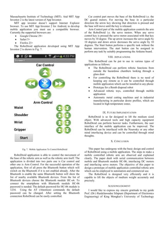
III. ASSEMBLING THE ROBODROID
A. Making The Chassis
The chassis carry the whole weight of the robot and
functions as the moving base of the RoboDroid. The base will
carry the robotic arm to the desired position. The base is made
up of sun mica sheet. The Arduino board, motor driver
circuitry and the power supply is bolted on the movable base.
For the rear wheel’s function DC geared motors are used and
ball bearings are functioning as front wheel as shown in Fig. 1
shown below.
Fig. 1. Chassis of RoboDroid](https://image.slidesharecdn.com/robodroidpaper-170801090933/85/MOBILE-CONTROLLED-ROBOTIC-ARM-USING-ARDUINO-AND-HC-06-2-320.jpg)

![Thonburi, Bangkok (Thailand) for her excellent direction and
encouragement. I am also thankful to Prof. Satish Rai
(Assistant Professor) BKBIET Pilani, for his suggestion and
support. I express much gratitude to my family, friends and
everyone who contributed to this project.
REFERENCES
[1] Jegede Olawale, Awodele Oludele, Ajayi Ayodele,
“Development of a Microcontroller Based Robotic Arm”, in
Proceedings of the 2007 Computer Science and IT Education
Conference pg: 549-557.
[2] https://en.wikipedia.org/wiki/Robotic_arm
[3] A.Rama Krishna, G. Sowmya Bala, A.S.C.S. Sastry, B. Bhanu
Prakash Sarma, Gokul Sai Alla, "Design And Implementation of
A Robotic Arm Based On Haptic Technology" ISSN: 2248-
9622, www.ijera.com Vol. 2, Issue 3, May-Jun 2012, pp.3098-
3103
[4] http://www.codevista.net/269/introduction-to-the-arduino-
platform-and-why-you-need-one
[5] http://www.codevista.net/182/how-to-connect-bluetooth-
module-hc-06-with-arduino-uno
[6] http://www.ti.com/lit/ds/symlink/l293.pdf
[7] https://en.wikipedia.org/wiki/Servomotor
[8] http://www.codevista.net/154/how-to-make-a-mobile-
controlled-robotic-arm-using-arduino-uno
[9] ai2.appinventor.mit.edu
[10] http://www.arduino.cc](https://image.slidesharecdn.com/robodroidpaper-170801090933/85/MOBILE-CONTROLLED-ROBOTIC-ARM-USING-ARDUINO-AND-HC-06-6-320.jpg)