Download to read offline
![International Research Journal of Engineering and Technology (IRJET) e-ISSN: 2395-0056
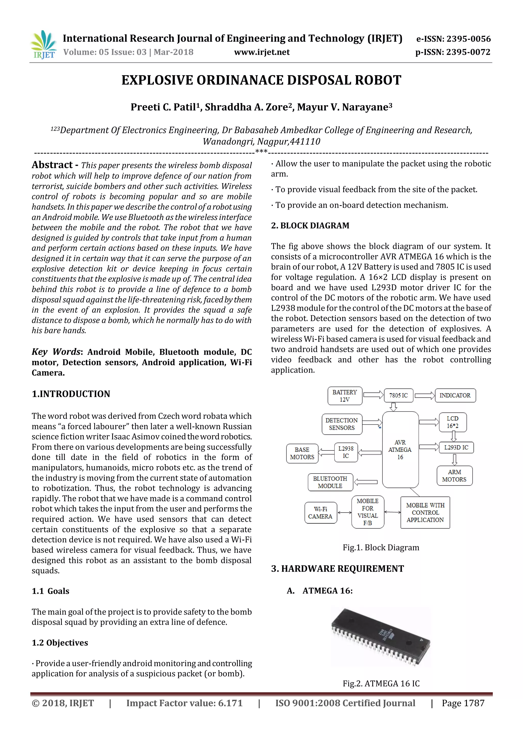
Volume: 05 Issue: 03 | Mar-2018 www.irjet.net p-ISSN: 2395-0072
© 2018, IRJET | Impact Factor value: 6.171 | ISO 9001:2008 Certified Journal | Page 1792
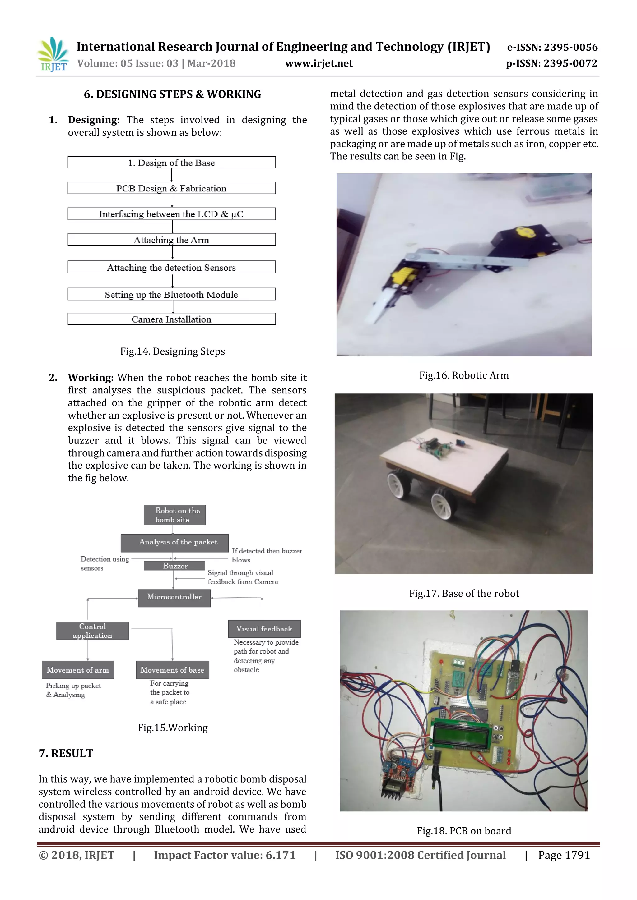
Fig.19. Complete view of the EOD
8. CONCLUSION
The Wireless Bomb Disposal Robot has been designed in
such a way that it can cater to the needsof the bombdisposal
squad, the military, the police and also forthepersonnelwho
handle radioactive materials. It has countless applications
and can be used in different environmentsandscenarios.For
instance, at one place it can be used by the bomb disposal
squad, while at another instance it can be used for handling
mines. While another application is to provide up to date
information in a hostage situation. The major advantages of
this robot are:
· It can be altered to suit the needs of the user
· It can be controlled remotely.
· It has video feedback.
· It has its own power supply.
· It has a detection mechanism using sensor hencenoneedof
separate detection mechanism.
9. ACKNOWLEDGEMENT
We are deeply indebted, and we would like to express our
sincere thanks to our project guides Mrs. Pradnya Morey
mam and Dr. S N Nagtode for providing usan opportunity to
do this work. Our special gratitude to Prof. Mrs. M.R. Patil
(HOD, Department of ElectronicsEngineering, DBACER.)for
her guidance, constant encouragement and whole-hearted
support. Finally, I would liketo expressmy sincere thanksto
all the staff members of EN Department for their valuable
guidance & support.
10. APPLICATIONS
We will design it as an assistant robot to the bomb disposal
squad but there are several other applications of this robot.
It can be used by:
Police: In hostage situations
Military: For reconnaissance missions
Fire Fighters: To provide video feedback of the site
for further analysis.
Nuclear fighters: For handling hazardous or
radioactive materials.
11. FUTURE SCOPE
The system that we have built is a working prototype of a
robot, which should be compact, fast and accurate. This
prototype may not have the features and reliability of the
original design. It is only being developed to ensure that the
design is feasible, not impractical and can be implemented
on a much larger scale in a more efficient way.
Hence the future enhancementsmay includeamuchsmaller,
faster, and more reliable machine. It may have the ability to
handle a much wider range of objects and the ability to
manoeuvre them to much safer places. Some of these
enhancements are described below.
· Compact Design
· Quick Movement
· Improved Reliability
· Removable Gripper/Multi-Gripper Robotic Arm
· Artificial Intelligence
· Night Vision Camera
12. REFERENCES
1). Shamyl bin Mansoor [1] Department of Computer
Engineering, Sir Syed University of Engineering and
Technology, Karachi, IEEE conference on “Wireless bomb
disposal robot” volume: 11 [2]
2). Jackrin Suthkorn from Department of Mechanical
Engineering, Johns HopkinsUniversity,Baltimore,Maryland,
IEEE conference on “Automatic Self-replicating robotic
system” volume:6
3). Mr. Ranjeet P. Rajmane1, Miss. Yogita Y. Patil2, Miss.
Shital K. Supugade3 E&TC Department DACOE, KARAD.
International Journal of Advanced Research in Electronics
and Communication Engineering (IJARECE) Volume 5, Issue
3.
4). Matthew W. Carey (RBE/ECE), Eric M. Kurtz (RBE),
Joshua D. Matte (ME), Timothy D. Perrault (RBE), Worcester
Polytechnic Institute. Novel EOD Robot Design with a
Dexterous Gripper and Intuitive Teleoperation
5). Tse TIJ Dept. of Mech. Eng., Nat. Cheng Kung University.,
Tainan, Taiwan Hsu, Ms. Lin, R.X. IEEE conference on
“Development of a mobile robot for visually guidedhandling
of material” volume:3.
6). Robotics by James L. Fuller Published by: Prentice Hall
Publication.
7). 1 Shinde Pushpa, 2 Davane Rahul., 3 Patil Poonam.
Department of Electronics and telecommunication Anna
Saheb Dange College of Engineering and Technology, Ashta
Wireless Bomb Disposal Robot, International Research
Journal of Engineering and Technology (IRJET)e-ISSN:2395
-0056 Volume: 03 Issue: 04.](https://image.slidesharecdn.com/irjet-v5i3401-190124093537/75/IRJET-Explosive-Ordinanace-Disposal-Robot-6-2048.jpg)

This document describes a wireless bomb disposal robot designed to assist bomb squads. The robot uses an Android mobile device for control via Bluetooth and has sensors to detect explosive materials. It has a robotic arm, cameras for visual feedback, and is designed to provide safety for bomb squads by allowing disposal of bombs from a distance. The robot's hardware includes an ATmega16 microcontroller, Bluetooth module, motors, sensors for explosive detection, and a camera for visual feedback to the mobile device. The goal is to provide an extra layer of protection for bomb disposal squads.

![[YOUSUNG] Product Catalog](https://cdn.slidesharecdn.com/ss_thumbnails/yousungcatalog-180810042638-thumbnail.jpg?width=640&height=640&fit=bounds)


![Seller Deck - Presentation [Concert L2].PPTX](https://cdn.slidesharecdn.com/ss_thumbnails/sellerdeck-presentationconcertl2-251219171156-24982daf-thumbnail.jpg?width=640&height=640&fit=bounds)


