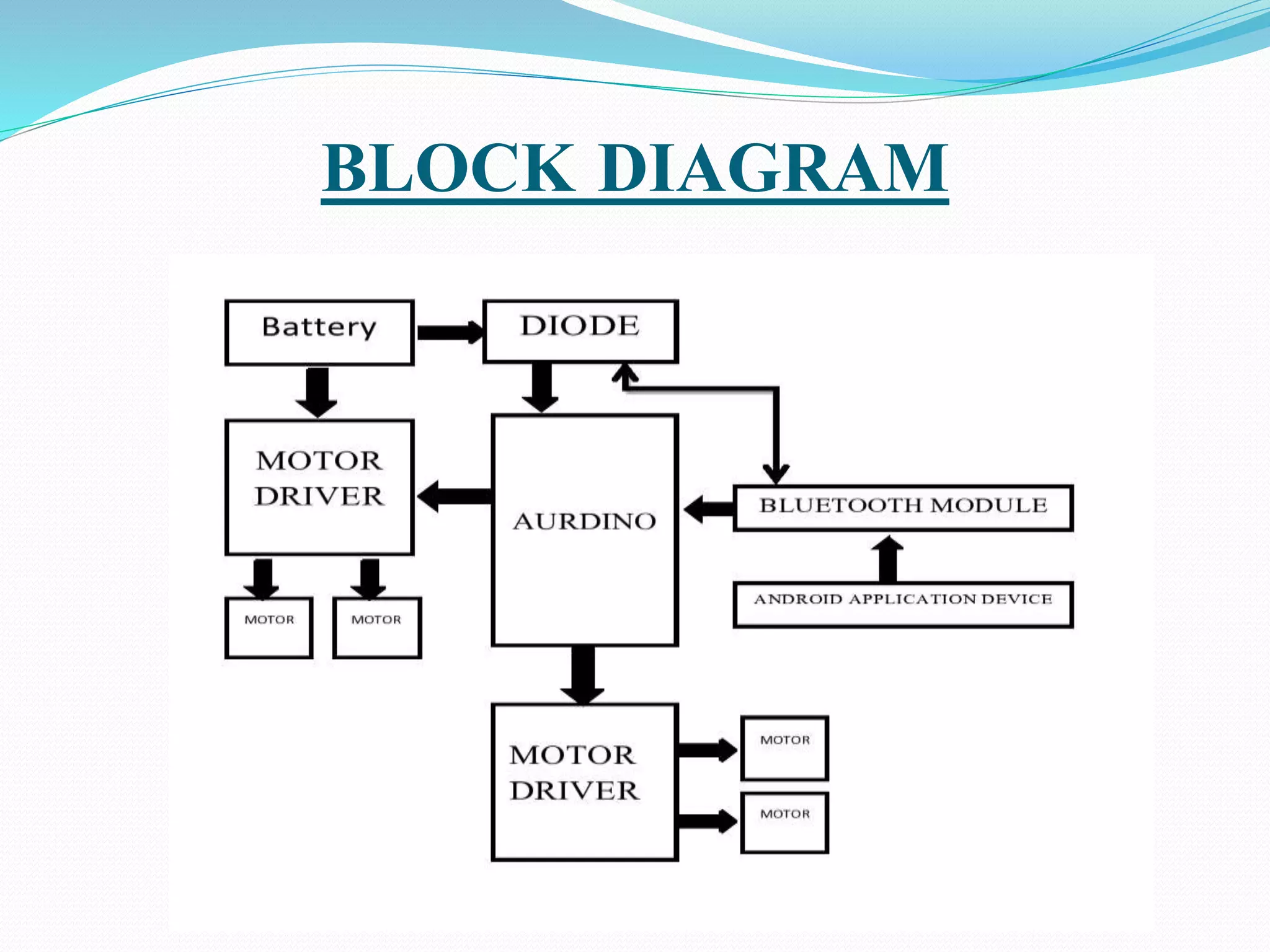
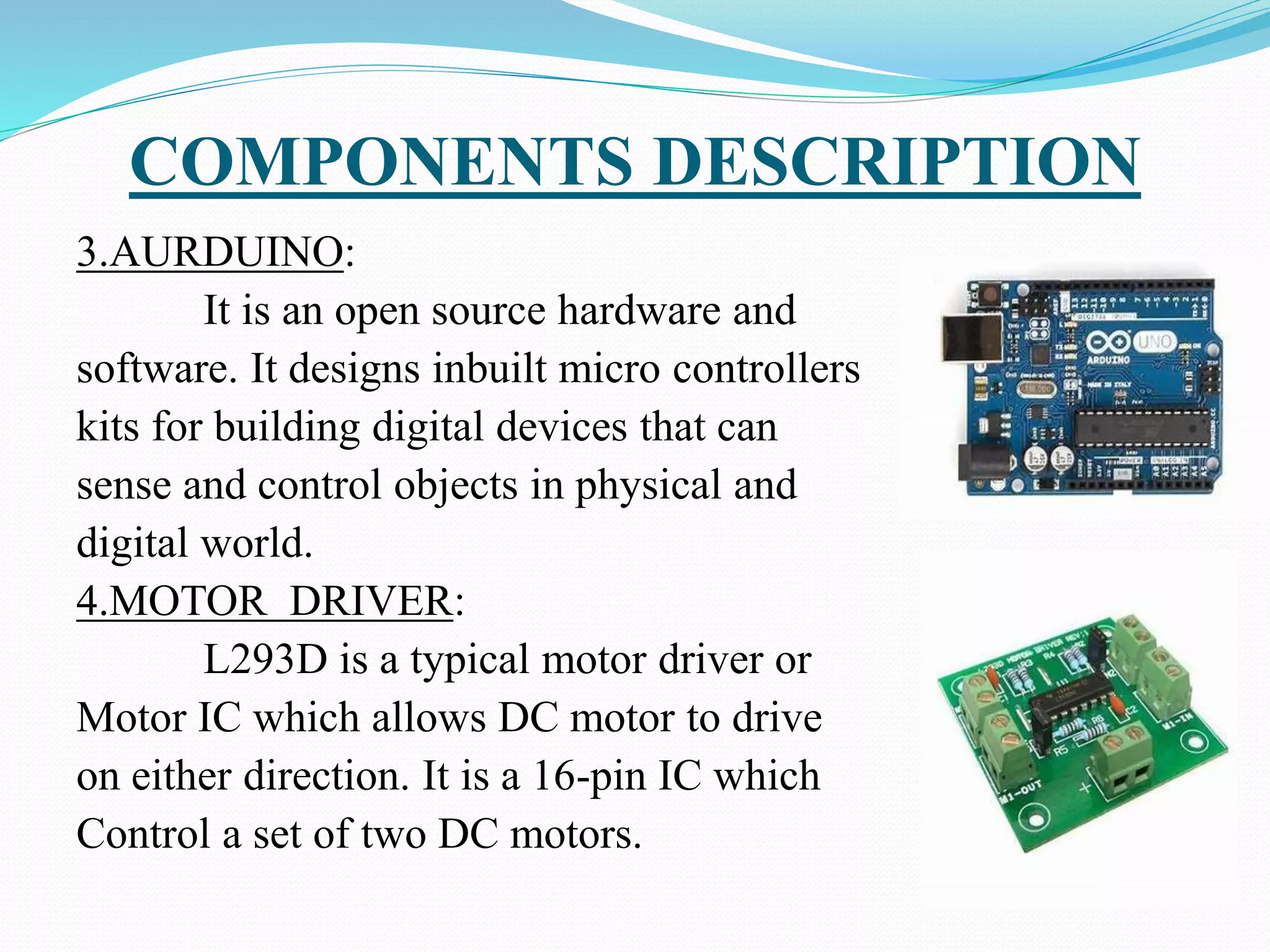
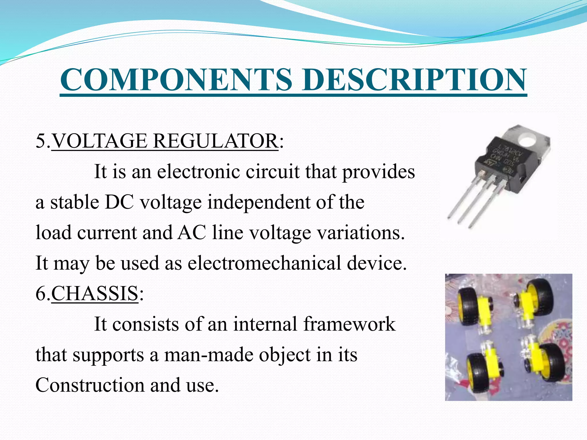
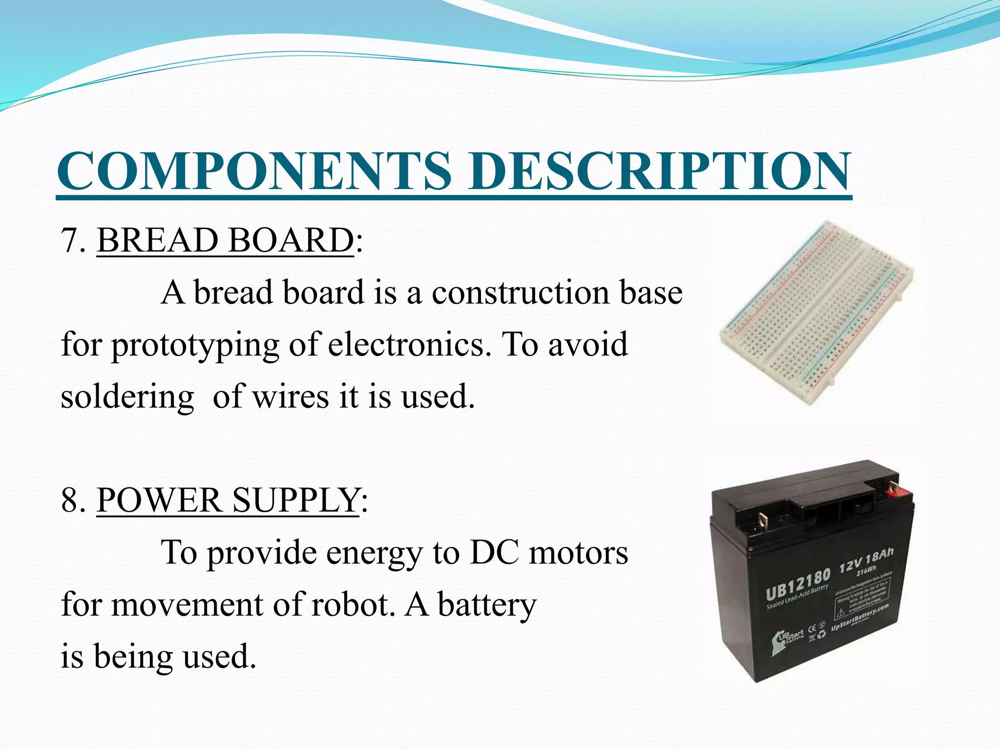
Project Guide: Mrs.V.N.Sireesha M.Tech
(Associate Prof,Dept. Of E.C.E)
Project Associates:
R.V. Tejaswini
Patnaik
J.V.R. Rakesh M. Murali Sai
Kumar
P. Akash Rao
16B61A0459 16B61A0427 16B61A0439 16B61A0447
CONTENT
1. Introduction
2. Objective
3. Existing Methods
4. Proposed Method
5. Block Diagram
6. Robotic terminology
7. Main Components
8. Mobile applications
9. Specifications and parts used
10. Components Description
11. Applications
12. Advantages
INTRODUCTION
A robot is an automatic mechanical device guided by a
computer program or electronic circuit.
In highly developing society automation playing an
important role to save human efforts in the most of
regular carried works.
Ex. Most of industrial jobs like welding, assembly,
container filling etc. Most commonly performed work is
picking and placing of jobs from source to destination.
For this pick and place robot is used.
OBJECTIVE
The primary object of the system is to design in such
a way that user can operate the robot through remote
controlling via Bluetooth. This involves the
movement of both robotic arm and vehicle in
synchronous with user's guidelines.
By interfacing the robotic vehicle with robotic arm ,
moment of the arm will be easy such that the work
can be done at multiple places.
 This system achieves a semi-automatic robotic arm.
EXISTING METHODS
Till now humanoid arms are designed and built to
mimic human form and movement.
They are meant to resemble the size and physical
abilities of a human in order to function in human-
oriented environments.
The Robotic vehicle adopts an algorithm to avoid
obstacles and the dexterous hand is capable of
grasping objects.
These kind of arms are not capable of performing
industrial works because of their kind of design.
PROPOSED METHOD
Combining the vehicle with the robotic arm is the
main method for achieving the semi-automation.
By using the vehicles more accurate results can be
obtained and do not fatigue while doing back-
breaking movements that may be difficult for
humans.
This is a mechatronic system which can be used for
picking the object from source location and places at
desired location.
These systems are versatile and can be reprogrammed
and tooled to provide multiple applications and can
easily perform industrial works.
BLOCK DIAGRAM
BLOCK DIAGRAM EXPLANATION
The AURDUINO UNO is the main controller of the
robotic vehicle.
The battery and diode is connected to the aurduino ,
which gives input to the aurduino.
The two motors were connected to the motor driver.
The both motor drivers are used, one is for arm
operation and another for vehicle operation.
ROBOTIC TERMINOLOGY
Link: A rigid piece of material connecting joints in robot.
Joint : The device which allow relative motion between
two adjoining link of robot.
ROBOTICS MOVEMENT:
Rotational movement
Radial movement
Vertical movement
MAIN COMPONENTS
Arms or Manipulator
Motor driver
Aurduino board
Bluetooth module
Gesture control
Chassis
OPERATION OF ARM
Pick and Place Robot is a mechatronic system that picks
from source location and places at desired location.
By using ultrasonic sensor while an obstacle is being
sensed then automatically car stops for smooth transport
of the material.
With end effectors the object is picked up and moves to
the desired location.
Mobile Pick and Place Robots speeds up the process of
picking and placing them in new locations, while also
increasing production rates.
OPERATION OF VEHICLE
The controlling of the vehicle is done by gesture
control or using app.
 These vehicles are more accurate and do not fatigue
while doing back-breaking movements that may be
difficult for humans.
The consistency, quality and reliability of pick and
place vehicle system is unmatched. These systems are
also versatile and can be reprogrammed and tooled to
provide multiple applications.
The vehicle will move rotational radial and vertical
motions.
By using an app we can control the vehicle and arm of
the robot .
The arm will turns around 180 degrees.
The vehicle will turns around 360 degrees.
MOTOR DRIVER PIN DIAGRAM
MOTOR DRIVER APPLICATION
 L293D contains two inbuilt H-bridge driver circuits. In its
common mode of operation, two DC motors can be driven
simultaneously, both in forward and reverse direction.
 The motor operations of two motors can be controlled by input
logic at pins 2 & 7 and 10 & 15.
 Input logic 00 or 11 will stop the corresponding motor.
 Logic 01 and 10 will rotate it in clockwise and anticlockwise
directions, respectively.
 Enable pins 1 and 9 (corresponding to the two motors)
must be high for motors to start operating.
PIN DESCRIPTION OF ARDUINO UNO
AURUDUINO ARCHITECHTURE
 Basically, the processor of the Aurduino board uses
the Harvard architecture where the program code and
program data have separate memory.
It consists of two memories such as program memory
and data memory.
Wherein the data is stored in data memory and the
code is stored in the flash program memory.
The Atmega328 microcontroller has 32kb of flash
memory, 2kb of SRAM 1kb of EPROM and operates
with a 16MHz clock speed.
BLUETOOTH MODULE
The Bluetooth module HC-05 is a MASTER/SLAVE
module. By default the factory setting is SLAVE.
The Role of the module (Master or Slave) can be
configured only by AT COMMANDS.
The slave modules cannot initiate a connection to
another Bluetooth device, but can accept connections.
 Master module can initiate a connection to other
devices.
The user can use it simply for a serial port replacement
to establish connection between MCU and GPS, PC to
your embedded project, etc.
GESTURE CONTROLS
Gestures are an important aspect of human
interaction, both interpersonally and in the context of
man-machine interfaces by using the Bluetooth
module.
A gesture is a non-verbal communication in which
visible bodily actions communicate particular
messages, either in place of speech or together and in
parallel with words.
Gestures include movement of the hands, face or other
parts of the body.
A BASIC WORKING OF THE GESTURE
RECOGNITION SYSTEM
CHASSIS
“Chassis” a French term which means the complete
Automobiles without Body and it includes all the
systems like power plant, transmission, steering,
suspension , wheels tires , auto electric system etc.
without body.
If body is also attached to it them it is known as the
particular vehicle as per the shape and design of the
body.
MOBILE APPLICATIONS
Bluetooth RC controller:
This application is designed to be used with a
MODIFIED RC car.
 You have to replace the car's stock control circuit
with a micro controller. This involves programming.
The application allows you to control an Aurduino
based RC car over Bluetooth. This is done using a
Bluetooth enabled Android phone.
HOME PAGE OF APPLICATION
The app lets you control the car with either buttons or
the phone's accelerometer.
A slider bar allows you to control your car's velocity if
the car's control circuit has this feature.
There are also two buttons for front and back lights.
A flashing light lets you know when the phone is
connected to the car, and arrows light up letting you
know the car's driving direction.
MIT APP INVENTOR:
App Inventor for Android is an open-source web
application originally provided by Google, and now
maintained by the Massachusetts Institute of
Technology (MIT).
It allows newcomers to computer programming to
create software applications for the Android operating
system (OS).
App Inventor emphasizes that programming can be a
vehicle for engaging powerful ideas through active
learning.
SPECIFICATION OF PARTS USED
Chassis material - Glass
Load carrying capacity - <100gm
Motor Rpm - 150rpm
Motor driver - L293D
Aurduino board - UNO
Voltage regulators - 7805,7812
Bluetooth module -HC05
Gesture Control
Bread board
COMPONENTS DESCRIPTION
1. BO-MOTOR:
Generally these motors are used
for running the wheels by converting
electrical energy into mechanical
energy.
2. SERVO MOTOR:
A servo motor is a rotary actuator or
Linear actuator that allows for precise
Control of angular or linear position,
Velocity and acceleration.
COMPONENTS DESCRIPTION
3.AURDUINO:
It is an open source hardware and
software. It designs inbuilt micro controllers
kits for building digital devices that can
sense and control objects in physical and
digital world.
4.MOTOR DRIVER:
L293D is a typical motor driver or
Motor IC which allows DC motor to drive
on either direction. It is a 16-pin IC which
Control a set of two DC motors.
COMPONENTS DESCRIPTION
5.VOLTAGE REGULATOR:
It is an electronic circuit that provides
a stable DC voltage independent of the
load current and AC line voltage variations.
It may be used as electromechanical device.
6.CHASSIS:
It consists of an internal framework
that supports a man-made object in its
Construction and use.
COMPONENTS DESCRIPTION
7. BREAD BOARD:
A bread board is a construction base
for prototyping of electronics. To avoid
soldering of wires it is used.
8. POWER SUPPLY:
To provide energy to DC motors
for movement of robot. A battery
is being used.
APPLICATIONS
Pick & Place
Material handling
Industrial Robot applications
Welding & Spraying
Trimming and sealing
ADVANTAGES
 Speed
 Accuracy
 Reliability
 Flexibility
 Affordability
THANK YOU

extra%20BATCH11_REVIEW%20FINAL%20_11_ppt.pptx

  • 1.
    Project Guide: Mrs.V.N.SireeshaM.Tech (Associate Prof,Dept. Of E.C.E) Project Associates: R.V. Tejaswini Patnaik J.V.R. Rakesh M. Murali Sai Kumar P. Akash Rao 16B61A0459 16B61A0427 16B61A0439 16B61A0447
  • 2.
    CONTENT 1. Introduction 2. Objective 3.Existing Methods 4. Proposed Method 5. Block Diagram 6. Robotic terminology 7. Main Components 8. Mobile applications 9. Specifications and parts used 10. Components Description 11. Applications 12. Advantages
  • 3.
    INTRODUCTION A robot isan automatic mechanical device guided by a computer program or electronic circuit. In highly developing society automation playing an important role to save human efforts in the most of regular carried works. Ex. Most of industrial jobs like welding, assembly, container filling etc. Most commonly performed work is picking and placing of jobs from source to destination. For this pick and place robot is used.
  • 4.
    OBJECTIVE The primary objectof the system is to design in such a way that user can operate the robot through remote controlling via Bluetooth. This involves the movement of both robotic arm and vehicle in synchronous with user's guidelines. By interfacing the robotic vehicle with robotic arm , moment of the arm will be easy such that the work can be done at multiple places.  This system achieves a semi-automatic robotic arm.
  • 5.
    EXISTING METHODS Till nowhumanoid arms are designed and built to mimic human form and movement. They are meant to resemble the size and physical abilities of a human in order to function in human- oriented environments. The Robotic vehicle adopts an algorithm to avoid obstacles and the dexterous hand is capable of grasping objects. These kind of arms are not capable of performing industrial works because of their kind of design.
  • 6.
    PROPOSED METHOD Combining thevehicle with the robotic arm is the main method for achieving the semi-automation. By using the vehicles more accurate results can be obtained and do not fatigue while doing back- breaking movements that may be difficult for humans.
  • 7.
    This is amechatronic system which can be used for picking the object from source location and places at desired location. These systems are versatile and can be reprogrammed and tooled to provide multiple applications and can easily perform industrial works.
  • 8.
  • 9.
    BLOCK DIAGRAM EXPLANATION TheAURDUINO UNO is the main controller of the robotic vehicle. The battery and diode is connected to the aurduino , which gives input to the aurduino. The two motors were connected to the motor driver. The both motor drivers are used, one is for arm operation and another for vehicle operation.
  • 10.
    ROBOTIC TERMINOLOGY Link: Arigid piece of material connecting joints in robot. Joint : The device which allow relative motion between two adjoining link of robot. ROBOTICS MOVEMENT: Rotational movement Radial movement Vertical movement
  • 11.
    MAIN COMPONENTS Arms orManipulator Motor driver Aurduino board Bluetooth module Gesture control Chassis
  • 12.
    OPERATION OF ARM Pickand Place Robot is a mechatronic system that picks from source location and places at desired location. By using ultrasonic sensor while an obstacle is being sensed then automatically car stops for smooth transport of the material. With end effectors the object is picked up and moves to the desired location. Mobile Pick and Place Robots speeds up the process of picking and placing them in new locations, while also increasing production rates.
  • 13.
    OPERATION OF VEHICLE Thecontrolling of the vehicle is done by gesture control or using app.  These vehicles are more accurate and do not fatigue while doing back-breaking movements that may be difficult for humans. The consistency, quality and reliability of pick and place vehicle system is unmatched. These systems are also versatile and can be reprogrammed and tooled to provide multiple applications.
  • 14.
    The vehicle willmove rotational radial and vertical motions. By using an app we can control the vehicle and arm of the robot . The arm will turns around 180 degrees. The vehicle will turns around 360 degrees.
  • 15.
  • 16.
    MOTOR DRIVER APPLICATION L293D contains two inbuilt H-bridge driver circuits. In its common mode of operation, two DC motors can be driven simultaneously, both in forward and reverse direction.  The motor operations of two motors can be controlled by input logic at pins 2 & 7 and 10 & 15.  Input logic 00 or 11 will stop the corresponding motor.  Logic 01 and 10 will rotate it in clockwise and anticlockwise directions, respectively.  Enable pins 1 and 9 (corresponding to the two motors) must be high for motors to start operating.
  • 17.
    PIN DESCRIPTION OFARDUINO UNO
  • 18.
    AURUDUINO ARCHITECHTURE  Basically,the processor of the Aurduino board uses the Harvard architecture where the program code and program data have separate memory. It consists of two memories such as program memory and data memory. Wherein the data is stored in data memory and the code is stored in the flash program memory. The Atmega328 microcontroller has 32kb of flash memory, 2kb of SRAM 1kb of EPROM and operates with a 16MHz clock speed.
  • 19.
    BLUETOOTH MODULE The Bluetoothmodule HC-05 is a MASTER/SLAVE module. By default the factory setting is SLAVE. The Role of the module (Master or Slave) can be configured only by AT COMMANDS. The slave modules cannot initiate a connection to another Bluetooth device, but can accept connections.  Master module can initiate a connection to other devices. The user can use it simply for a serial port replacement to establish connection between MCU and GPS, PC to your embedded project, etc.
  • 20.
    GESTURE CONTROLS Gestures arean important aspect of human interaction, both interpersonally and in the context of man-machine interfaces by using the Bluetooth module. A gesture is a non-verbal communication in which visible bodily actions communicate particular messages, either in place of speech or together and in parallel with words. Gestures include movement of the hands, face or other parts of the body.
  • 21.
    A BASIC WORKINGOF THE GESTURE RECOGNITION SYSTEM
  • 22.
    CHASSIS “Chassis” a Frenchterm which means the complete Automobiles without Body and it includes all the systems like power plant, transmission, steering, suspension , wheels tires , auto electric system etc. without body. If body is also attached to it them it is known as the particular vehicle as per the shape and design of the body.
  • 23.
    MOBILE APPLICATIONS Bluetooth RCcontroller: This application is designed to be used with a MODIFIED RC car.  You have to replace the car's stock control circuit with a micro controller. This involves programming. The application allows you to control an Aurduino based RC car over Bluetooth. This is done using a Bluetooth enabled Android phone.
  • 24.
    HOME PAGE OFAPPLICATION
  • 25.
    The app letsyou control the car with either buttons or the phone's accelerometer. A slider bar allows you to control your car's velocity if the car's control circuit has this feature. There are also two buttons for front and back lights. A flashing light lets you know when the phone is connected to the car, and arrows light up letting you know the car's driving direction.
  • 26.
    MIT APP INVENTOR: AppInventor for Android is an open-source web application originally provided by Google, and now maintained by the Massachusetts Institute of Technology (MIT). It allows newcomers to computer programming to create software applications for the Android operating system (OS). App Inventor emphasizes that programming can be a vehicle for engaging powerful ideas through active learning.
  • 27.
    SPECIFICATION OF PARTSUSED Chassis material - Glass Load carrying capacity - <100gm Motor Rpm - 150rpm Motor driver - L293D Aurduino board - UNO Voltage regulators - 7805,7812 Bluetooth module -HC05 Gesture Control Bread board
  • 28.
    COMPONENTS DESCRIPTION 1. BO-MOTOR: Generallythese motors are used for running the wheels by converting electrical energy into mechanical energy. 2. SERVO MOTOR: A servo motor is a rotary actuator or Linear actuator that allows for precise Control of angular or linear position, Velocity and acceleration.
  • 29.
    COMPONENTS DESCRIPTION 3.AURDUINO: It isan open source hardware and software. It designs inbuilt micro controllers kits for building digital devices that can sense and control objects in physical and digital world. 4.MOTOR DRIVER: L293D is a typical motor driver or Motor IC which allows DC motor to drive on either direction. It is a 16-pin IC which Control a set of two DC motors.
  • 30.
    COMPONENTS DESCRIPTION 5.VOLTAGE REGULATOR: Itis an electronic circuit that provides a stable DC voltage independent of the load current and AC line voltage variations. It may be used as electromechanical device. 6.CHASSIS: It consists of an internal framework that supports a man-made object in its Construction and use.
  • 31.
    COMPONENTS DESCRIPTION 7. BREADBOARD: A bread board is a construction base for prototyping of electronics. To avoid soldering of wires it is used. 8. POWER SUPPLY: To provide energy to DC motors for movement of robot. A battery is being used.
  • 32.
    APPLICATIONS Pick & Place Materialhandling Industrial Robot applications Welding & Spraying Trimming and sealing
  • 33.
    ADVANTAGES  Speed  Accuracy Reliability  Flexibility  Affordability
  • 34.