The document is a project report on 'Home Automation Using Mobile Application' submitted for the Bachelor of Technology in Electrical Engineering by Eklavya Sharma and Rakesh Sharma. It outlines the design and implementation of a smart home automation system utilizing Arduino, Bluetooth, and mobile applications, focusing on enhancing energy efficiency and user convenience. The report includes technical details, component specifications, and future improvement suggestions for the system.

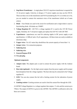
![13
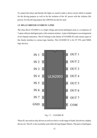
in ULN2003 is esteemed at 500mA and can withstand peak current of 600mA.In the pin layout,
the i/ps & o/ps are provided reverse to each other. Each driver also has a suppression diode to
dissipate voltage spikes while driving inductive loads.
The ULN2003 has a 2.7kΩ series base resistor for each Darlington pair for operation directly
with TTL or 5V CMOS devices. The ULN2003 is known for its high-current, high-voltage
capacity. The drivers can be paralleled for even higher current output. Even further, stacking
one chip on top of another, both electrically and physically, has been done. Generally it can
also be used for interfacing with a stepper motor, where the motor requires high ratings which
cannot be provided by other interfacing devices.
Features:
500mA rated collector current(Single output)
High-voltage outputs: 50V
Inputs compatible with various types of logic.
Relay driver application
Inputs pinned opposite outputs to simplify layout
Seven Darlington’s per package
A Darlington transistor (also known as Darlington pair) achieves very high current
amplification by connecting two bipolar transistors in direct DC coupling so the current
amplified by the first transistor is amplified further by the second one. The resultant current
gain is the product of those of the two component transistors:
The seven Darlington pairs in ULN2003 can operate independently except the common
cathode diodes that connect to their respective collectors.
L293D IC:
The L293D is quadruple high-current half-H driver. The L293D is designed to provide
bidirectional drive currents of up to 600 milliampere at voltages from 4.5 Volts to 36 Volts.
L293D IC’s are designed to drive a wide array of inductive loads such as relays, solenoids, DC
and bipolar stepping motors, as well as other high-current and high-voltage loads [6]. Here, it](https://image.slidesharecdn.com/downloadfile-170801092717/85/SMART-HOME-AUTOMATION-USING-MOBILE-APPLICATION-21-320.jpg)
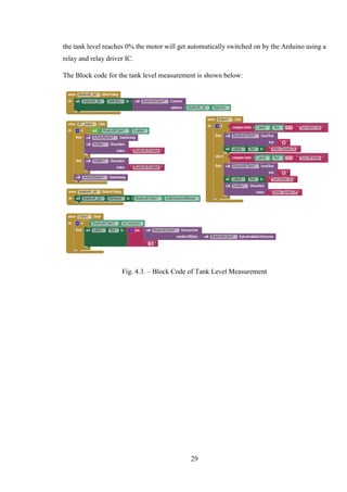
![40
4. “Ad-Hoc Low Powered 802.15.1 Protocol Based Automation System for Residence using
Mobile Devices”, Pradeep G., B. Santhi Chandra, M. Venkateswarao, Department of ECE,
K.L. University, Vijaywada, Andhra Pradesh, India IJCST Vol 2, SP 1, 2011
5. “Bluetooth Based Home Automation System using Cell Phone”, R Piyare, M. Tazil, IEEE
15th International Symposium on Consumer Electronics, 2011.
6. “Zigbee Based Home Automation”, Rana, Jitendra, Rajendra and Sunil N., April 2010.
7. “Safe and Secure PIC Based Remote Control Application for Intelligent Home”, E. Yavuz,
B. Hasan, I. Serkan and K. Duygu, International Journal of Computer Science and Network
Security, Vol 7. No. 5, May 2007.
8. “Towards Smart Home: Control Electrical Devices Online”, Muhammad Izhar Ramli,
Mohd. Wahab, Nabihah, Nornabihah Ahmad, International Conference on Science and
Technology: Application in Industry and Education, 2006.
9. “Java-Based Home Automation”, Al-Ali, Member IEEE & M. Al-Rousan, IEEE
Transaction on Consumer Electronics, Vol 50. No. 2, May 2004. [10] “Bluetooth Based
Home Automation System”, N. Sriskanthan and Tan Karand,Journal of Microprocessors
and Microsystems, Vol 26, 2002.
10. Hsien-Tang Lin" Implementing Smart Homes with Open Source Solutions" International
Journal of Smart Home Vol. 7, No. 4, July, 2013.
11. Rosslin John Robles1 and Tai-hoon Kim1" Applications, Systems and Methods in Smart
Home Technology: AReview" International Journal of Advanced Science and Technology
Vol. 15, February, 2010.
12. Sook-Ling Chua and Stephen Marsland and HansW. Guesgen" Beha viour Recognition
in Smart Homes Sook" Proceedings of the TwentySecond International Joint Conference
on Artificial Intelligence 2011.
13. Gowthami, Dr. Adiline macriga "Smart Home Monitoring and Con
trolling System Using Android Phone" International Journal of Emerging Technology and
Advanced Engineering Website: www.ijetae.com ISSN 2250-2459, ISO 9001:2008
Certified Journal, Volume 3, Issue 11, November 2013.
14. Saisakul Chernbumroong, Anthony S. Atkins, and Hongnian Yu Perception of Smart Home
Technologies to Assist Elderly People" 4th International conference on software,
Knowledge information manage and applications (SKIMA 2010).
15. Christian Reinisch, Mario J. Kofler, Wolfgang Kastner"ThinkHome: A Smart Home
as Digital Ecosystem" 4th IEEE International Conference on Digital Ecosystems and
Technologies (IEEE DEST 2010).](https://image.slidesharecdn.com/downloadfile-170801092717/85/SMART-HOME-AUTOMATION-USING-MOBILE-APPLICATION-48-320.jpg)


![Smart accident detector and intimator [autosaved]](https://cdn.slidesharecdn.com/ss_thumbnails/smartaccidentdetectorandintimatorautosaved-180331150920-thumbnail.jpg?width=640&height=640&fit=bounds)