Download to read offline


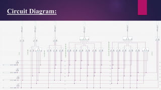


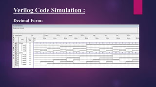


This document presents a mini project on designing a prime number generator circuit. It includes a problem statement, introduction, design process, logic design with a truth table and Karnaugh maps, circuit diagram, Verilog code simulation, analysis and conclusions. The design process generates up to 15 prime numbers using 4-bit input and 6-bit output. Karnaugh maps are used to simplify the Boolean expressions and derive the logic gate equations. The circuit and Verilog code are then simulated and the results analyzed. The presenters learned how to design digital logic circuits through this process.