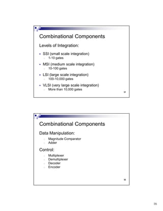
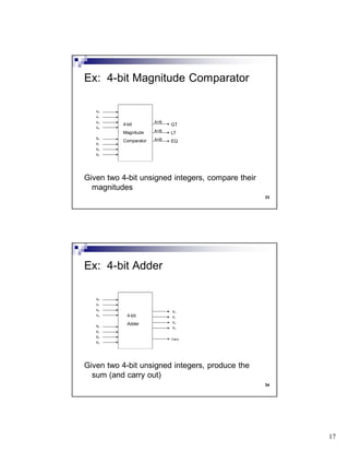
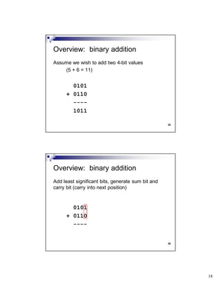
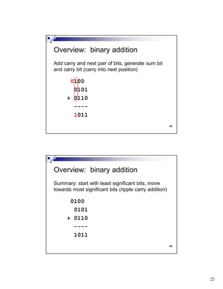
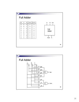
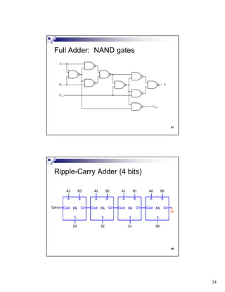
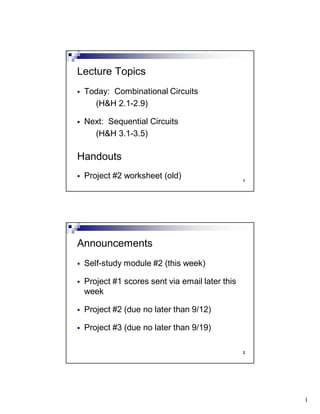
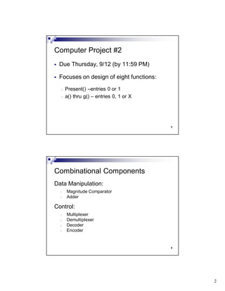
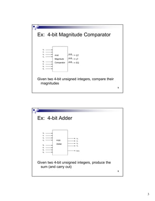
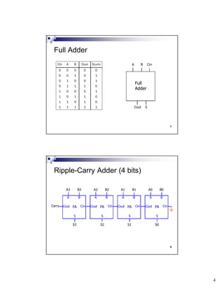
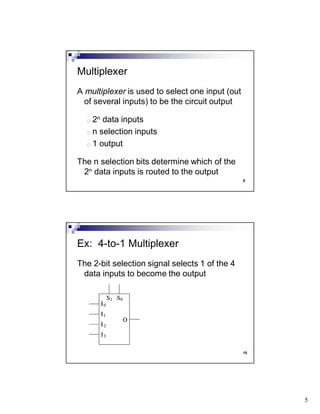
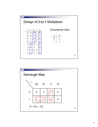
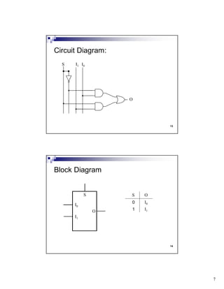
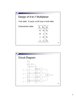
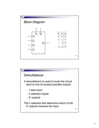
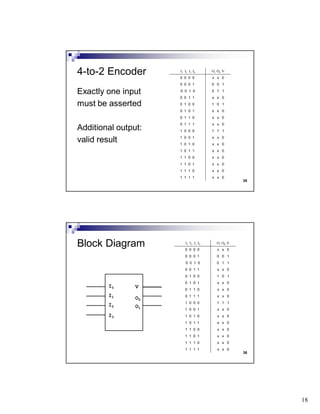
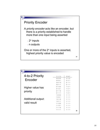
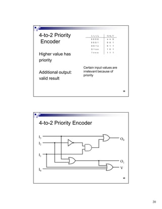
1. 1
1
Today: Combinational Circuits
(H&H 2.1-2.9)
Next: continued
Handouts
Project #2 worksheet
Lecture Topics
2
Consulting hours posted
Self-study module #1 (this week)
Project #1 (due no later than 9/5)
Project #2 (due no later than 9/12)
Announcements
2. 2
3
Due Thursday, 9/12 (by 11:59 PM)
Focuses on design of eight functions:
o Present() –entries 0 or 1
o a() thru g() – entries 0, 1 or X
Computer Project #2
4
Circuit design based on Boolean algebra
Three equivalent representations
o algebraic expressions
o truth tables
o circuit diagram
Combinational Circuits
3. 3
5
Expression in Boolean algebra:
F(A,B) = A'B + AB'
Truth table:
A B F(A,B)
0 0 0
0 1 1
1 0 1
1 1 0
Circuit diagram:
A B
F(A,B)
6
Canonical Sum-of-Products Form:
F(A,B) = A'B + AB'
The expression is the sum of a series of
products, where each product is a minterm
A minterm is a product where each
variable is present (complemented or
uncomplemented)
Standard Forms
4. 4
7
The following are in canonical SOP form:
F(A,B) = A'B' + A'B + AB'
G(A,B,C) = A'BC + AB'C + ABC' + ABC
H(A,B,C,D) = A'B'C'D' + A'B'CD + ABCD'
Examples
8
The following are equivalent:
F(A,B) = A'B' + A'B + AB'
F(A,B) = m0 + m1 + m2
F(A,B) = minterms( 0, 1, 2 )
Alternate notation (minterm lists)
5. 5
9
Ideally, a Boolean expression will be as
simple as possible and still generate the
correct values
The minimized (optimal, simplified) Boolean
expression for a particular function is the
one which has:
the fewest number of gates
the fewest number of inputs to gates
Minimization
10
Apply the postulates and theorems of
Boolean algebra:
AB' + AB = A(B' + B) (distributive law)
= A(1) (complement law)
= A (identity law)
Algebraic Manipulation
6. 6
11
Fill in the entries in a K-map, then inspect it
to identify the optimal expression
Karnaugh map is rectangular and has one
entry for each minterm – adjacent minterms
can be combined (same rules as algebraic
manipulation)
Karnaugh Map
12
Minimized function: F(A,B) = A
Ex: F(A,B) = AB' + AB
A' A
B' 0 1
B 0 1
A
0 1
B
0 0 1
1 0 1
7. 7
13
F(A,B,C) = B
Ex: F(A,B,C) = minterms( 2, 3, 6, 7 )
A'B' A'B AB AB'
C' 0 1 1 0
C 0 1 1 0
14
K-map for function with 4 inputs
A'B' A'B AB AB'
C'D' m0 m4 m12 m8
C'D m1 m5 m13 m9
CD m3 m7 m15 m11
CD' m2 m6 m14 m10
10. 10
19
Start with 1’s which are isolated
Find 1’s that can only be included in 2-cover
Find 1’s that can only be included in 4-cover
Find 1’s that can only be included in 8-cover
Continue until all 1’s covered at least once
Order is important!
20
K-maps are "circular":
11. 11
21
For some functions, there are particular
input combinations which cannot occur or
particular output values that won't be used
Those minterms are irrelevant (we don't
care whether the value of that minterm is a
0 or a 1)
Useful during minimization
Irrelevant minterms (don't cares)
22
Consider three functions (D,E,F) which use
the same three inputs (A,B,C):
If A or C is true, then function D is true
If A or B is true, then function E is true
Function F is true if exactly one of the inputs
is true. Furthermore, the value of function F
is irrelevant when functions D and E are true
12. 12
23
If A or C is true, then function D is true
If A or B is true, then function E is true
Function F is true if exactly one of the inputs is true. Furthermore, the
value of function F is irrelevant when functions D and E are true
A B C D E F
0 0 0 0 0 0
0 0 1 1 0 1
0 1 0 0 1 1
0 1 1 1 1 0
1 0 0 1 1 1
1 0 1 1 1 0
1 1 0 1 1 0
1 1 1 1 1 0
24
If A or C is true, then function D is true
If A or B is true, then function E is true
Function F is true if exactly one of the inputs is true. Furthermore, the
value of function F is irrelevant when functions D and E are true
A B C D E F
0 0 0 0 0 0
0 0 1 1 0 1
0 1 0 0 1 1
0 1 1 1 1 X
1 0 0 1 1 X
1 0 1 1 1 X
1 1 0 1 1 X
1 1 1 1 1 X
13. 13
25
D(A,B,C) = A + C
K-map for D(A,B,C)
AB
00 01 11 10
C
0 0 0 1 1
1 1 1 1 1
26
E(A,B,C) = A + B
K-map for E(A,B,C)
AB
00 01 11 10
C
0 0 1 1 1
1 0 1 1 1
14. 14
27
F(A,B,C) = B + C
K-map for F(A,B,C)
AB
00 01 11 10
C
0 0 1 X X
1 1 X X X
28
Consider a function where the input is a
base 6 number. The function is true when
the input is evenly divisible by 3.
Possible inputs: {0,1,2,3,4,5}
Function true when input is {0,3}
Example
15. 15
29
Function F is true if the input is evenly divisible by 3; the
input will be a base 6 number.
A B C F
0 0 0 1
0 0 1 0
0 1 0 0
0 1 1 1
1 0 0 0
1 0 1 0
1 1 0 X
1 1 1 X
30
F(A,B,C) = BC + A'B'C'
K-map for F(A,B,C)
AB
00 01 11 10
C
0 1 0 X 0
1 0 1 X 0
16. 16
31
Levels of Integration:
SSI (small scale integration)
o 1-10 gates
MSI (medium scale integration)
o 10-100 gates
LSI (large scale integration)
o 100-10,000 gates
VLSI (very large scale integration)
o More than 10,000 gates
Combinational Components
32
Data Manipulation:
o Magnitude Comparator
o Adder
Control:
o Multiplexer
o Demultiplexer
o Decoder
o Encoder
Combinational Components
17. 17
33
Given two 4-bit unsigned integers, compare their
magnitudes
Ex: 4-bit Magnitude Comparator
A0
A1
A2
A3
B0
B1
B2
B3
GT
LT
EQ
4-bit
Magnitude
Comparator
A>B
A<B
A=B
34
Given two 4-bit unsigned integers, produce the
sum (and carry out)
Ex: 4-bit Adder
A0
A1
A2
A3
B0
B1
B2
B3
4-bit
Adder
S0
S1
S2
S3
Carry
18. 18
35
Assume we wish to add two 4-bit values
(5 + 6 = 11)
0101
+ 0110
----
1011
Overview: binary addition
36
Add least significant bits, generate sum bit and
carry bit (carry into next position)
0101
+ 0110
----
Overview: binary addition
19. 19
37
Add least significant bits, generate sum bit and
carry bit (carry into next position)
0
0101
+ 0110
----
1
Overview: binary addition
38
Add carry and next pair of bits, generate sum bit
and carry bit (carry into next position)
0
0101
+ 0110
----
1
Overview: binary addition
20. 20
39
Add carry and next pair of bits, generate sum bit
and carry bit (carry into next position)
00
0101
+ 0110
----
11
Overview: binary addition
40
Add carry and next pair of bits, generate sum bit
and carry bit (carry into next position)
00
0101
+ 0110
----
11
Overview: binary addition
21. 21
41
Add carry and next pair of bits, generate sum bit
and carry bit (carry into next position)
100
0101
+ 0110
----
011
Overview: binary addition
42
Add carry and next pair of bits, generate sum bit
and carry bit (carry into next position)
100
0101
+ 0110
----
011
Overview: binary addition
22. 22
43
Add carry and next pair of bits, generate sum bit
and carry bit (carry into next position)
0100
0101
+ 0110
----
1011
Overview: binary addition
44
Summary: start with least significant bits, move
towards most significant bits (ripple carry addition)
0100
0101
+ 0110
----
1011
Overview: binary addition
23. 23
45
Full
Adder
A B
SCout
CinCin A B Cout S(um)
0 0 0 0 0
0 0 1 0 1
0 1 0 0 1
0 1 1 1 0
1 0 0 0 1
1 0 1 1 0
1 1 0 1 0
1 1 1 1 1
Full Adder
46
Full Adder
24. 24
47
Full Adder: NAND gates
48
A B
CinCout
S
S0
A0 B0
A B
CinCout
S
S1
A1 B1
A B
CinCout
S
S2
A2 B2
FA
A B
CinCout
S
FA FA FA
S3
A3 B3
Carry
Ripple-Carry Adder (4 bits)
25. 1
1
Today: Combinational Circuits
(H&H 2.1-2.9)
Next: Sequential Circuits
(H&H 3.1-3.5)
Handouts
Project #2 worksheet (old)
Lecture Topics
2
Self-study module #2 (this week)
Project #1 scores sent via email later this
week
Project #2 (due no later than 9/12)
Project #3 (due no later than 9/19)
Announcements
26. 2
3
Due Thursday, 9/12 (by 11:59 PM)
Focuses on design of eight functions:
o Present() –entries 0 or 1
o a() thru g() – entries 0, 1 or X
Computer Project #2
4
Data Manipulation:
o Magnitude Comparator
o Adder
Control:
o Multiplexer
o Demultiplexer
o Decoder
o Encoder
Combinational Components
27. 3
5
Given two 4-bit unsigned integers, compare their
magnitudes
Ex: 4-bit Magnitude Comparator
A0
A1
A2
A3
B0
B1
B2
B3
GT
LT
EQ
4-bit
Magnitude
Comparator
A>B
A<B
A=B
6
Given two 4-bit unsigned integers, produce the
sum (and carry out)
Ex: 4-bit Adder
A0
A1
A2
A3
B0
B1
B2
B3
4-bit
Adder
S0
S1
S2
S3
Carry
28. 4
7
Full
Adder
A B
SCout
CinCin A B Cout S(um)
0 0 0 0 0
0 0 1 0 1
0 1 0 0 1
0 1 1 1 0
1 0 0 0 1
1 0 1 1 0
1 1 0 1 0
1 1 1 1 1
Full Adder
8
A B
CinCout
S
S0
A0 B0
A B
CinCout
S
S1
A1 B1
A B
CinCout
S
S2
A2 B2
FA
A B
CinCout
S
FA FA FA
S3
A3 B3
Carry
Ripple-Carry Adder (4 bits)
29. 5
9
A multiplexer is used to select one input (out
of several inputs) to be the circuit output
o 2n data inputs
o n selection inputs
o 1 output
The n selection bits determine which of the
2n data inputs is routed to the output
Multiplexer
10
The 2-bit selection signal selects 1 of the 4
data inputs to become the output
Ex: 4-to-1 Multiplexer
32. 8
15
Truth table: 6 inputs, so 64 rows in truth table
Characteristic table:
Design of 4-to-1 Multiplexer
16
Circuit Diagram
33. 9
17
Block Diagram
18
A demultiplexer is used to route the circuit
input to one of several possible outputs
o 1 data input
o n selection inputs
o 2n outputs
The n selection bits determine which of the
2n outputs receives the input
Demultiplexer
36. 12
23
A decoder recognizes which encoded value
is the input to the circuit
o n inputs
o 2n outputs
One of the 2n outputs is asserted, based on
which encoded value is inputted
Decoder
24
The 2-bit input determines which one of the
4 output signals is asserted
Ex: 2-to-4 Decoder
38. 14
27
Block Diagram
I1 I0 O3 O2 O1 O0
0 0 0 0 0 1
0 1 0 0 1 0
1 0 0 1 0 0
1 1 1 0 0 0
28
A decoder recognizes which encoded value
is the input to the circuit, if it is enabled
o n inputs
o 1 control input (enable)
o 2n outputs
When enabled, one of the 2n outputs is
asserted, based encoded input value
Decoder with Enable Signal
39. 15
29
The 2-bit input determines which one of the
4 output signals is asserted
Ex: 2-to-4 Decoder
EN
30
Circuit Diagram
I1 I0
EN
40. 16
31
Block Diagram
EN
I1 I0 EN O3 O2 O1 O0
X X 0 0 0 0 0
0 0 1 0 0 0 1
0 1 1 0 0 1 0
1 0 1 0 1 0 0
1 1 1 1 0 0 0
32
A encoder recognizes which one input is
asserted and outputs that encoded value
o 2n inputs
o n outputs
One of the 2n inputs is asserted, and that
encoded value is outputted
Encoder
41. 17
33
One of the 4 input signals is asserted and
the encoded 2-bit value is the output
Ex: 4-to-2 Encoder
I3
I2
I1
I0
O1
O0
34
Exactly one input
must be asserted.
What if none?
What if more than
one?
4-to-2 Encoder I3 I2 I1 I0 O1 O0
0 0 0 0 ?
0 0 0 1 0 0
0 0 1 0 0 1
0 0 1 1 ?
0 1 0 0 1 0
0 1 0 1 ?
0 1 1 0 ?
0 1 1 1 ?
1 0 0 0 1 1
1 0 0 1 ?
1 0 1 0 ?
1 0 1 1 ?
1 1 0 0 ?
1 1 0 1 ?
1 1 1 0 ?
1 1 1 1 ?
42. 18
35
Exactly one input
must be asserted
Additional output:
valid result
4-to-2 Encoder I3 I2 I1 I0 O1 O0 V
0 0 0 0 x x 0
0 0 0 1 0 0 1
0 0 1 0 0 1 1
0 0 1 1 x x 0
0 1 0 0 1 0 1
0 1 0 1 x x 0
0 1 1 0 x x 0
0 1 1 1 x x 0
1 0 0 0 1 1 1
1 0 0 1 x x 0
1 0 1 0 x x 0
1 0 1 1 x x 0
1 1 0 0 x x 0
1 1 0 1 x x 0
1 1 1 0 x x 0
1 1 1 1 x x 0
36
Block Diagram
I3
I2
I1
I0
O1
O0
V
I3 I2 I1 I0 O1 O0 V
0 0 0 0 x x 0
0 0 0 1 0 0 1
0 0 1 0 0 1 1
0 0 1 1 x x 0
0 1 0 0 1 0 1
0 1 0 1 x x 0
0 1 1 0 x x 0
0 1 1 1 x x 0
1 0 0 0 1 1 1
1 0 0 1 x x 0
1 0 1 0 x x 0
1 0 1 1 x x 0
1 1 0 0 x x 0
1 1 0 1 x x 0
1 1 1 0 x x 0
1 1 1 1 x x 0
43. 19
37
A priority encoder acts like an encoder, but
there is a priority established to handle
more than one input being asserted
o 2n inputs
o n outputs
One or more of the 2n inputs is asserted,
highest priority value is encoded
Priority Encoder
38
Higher value has
priority
Additional output:
valid result
4-to-2 Priority
Encoder
I3 I2 I1 I0 O1 O0 V
0 0 0 0 x x 0
0 0 0 1 0 0 1
0 0 1 0 0 1 1
0 0 1 1 0 1 1
0 1 0 0 1 0 1
0 1 0 1 1 0 1
0 1 1 0 1 0 1
0 1 1 1 1 0 1
1 0 0 0 1 1 1
1 0 0 1 1 1 1
1 0 1 0 1 1 1
1 0 1 1 1 1 1
1 1 0 0 1 1 1
1 1 0 1 1 1 1
1 1 1 0 1 1 1
1 1 1 1 1 1 1
44. 20
39
Higher value has
priority
Additional output:
valid result
4-to-2 Priority
Encoder
I3 I2 I1 I0 O1 O0 V
0 0 0 0 x x 0
0 0 0 1 0 0 1
0 0 1 x 0 1 1
0 1 x x 1 0 1
1 x x x 1 1 1
Certain input values are
irrelevant because of
priority
40
4-to-2 Priority Encoder
I3
I2
I1
I0
V
O1
O0