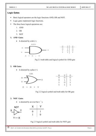
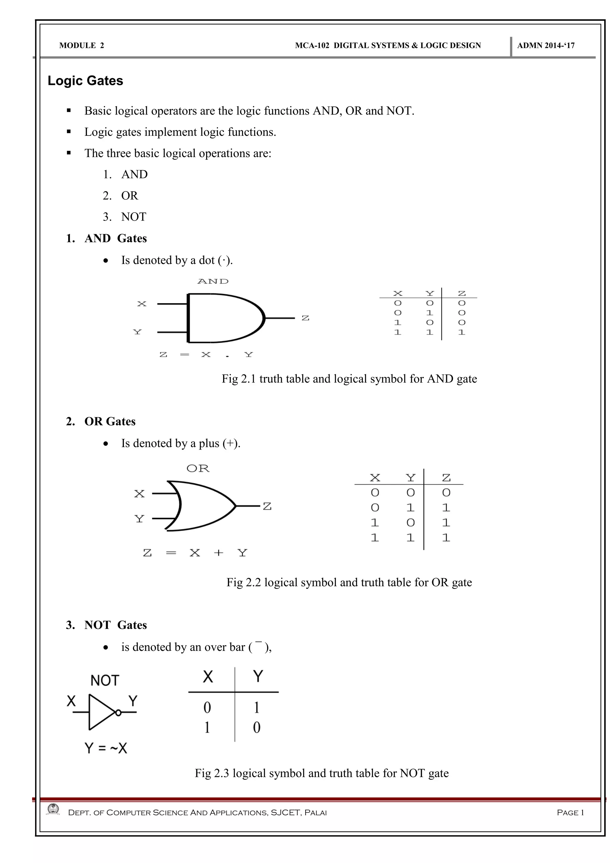
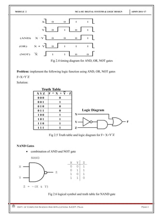
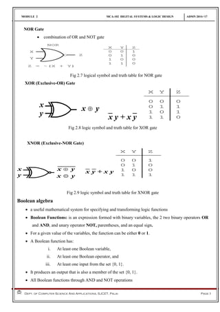
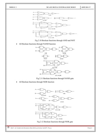
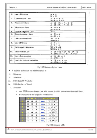
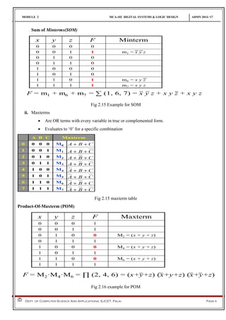
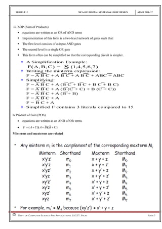
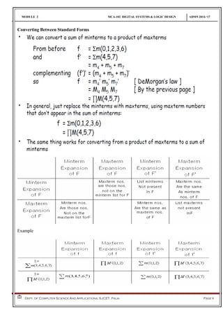
MODULE 2 MCA-102 DIGITAL SYSTEMS & LOGIC DESIGN ADMN 2014-‘17
Dept. of Computer Science And Applications, SJCET, Palai Page 1
Logic Gates
 Basic logical operators are the logic functions AND, OR and NOT.
 Logic gates implement logic functions.
 The three basic logical operations are:
1. AND
2. OR
3. NOT
1. AND Gates
 Is denoted by a dot (·).
Fig 2.1 truth table and logical symbol for AND gate
2. OR Gates
 Is denoted by a plus (+).
Fig 2.2 logical symbol and truth table for OR gate
3. NOT Gates
 is denoted by an over bar ( ¯ ),
Fig 2.3 logical symbol and truth table for NOT gate
MODULE 2 MCA-102 DIGITAL SYSTEMS & LOGIC DESIGN ADMN 2014-‘17
Dept. of Computer Science And Applications, SJCET, Palai Page 2
Fig 2.4 timing diagram for AND, OR, NOT gates
Problem: implement the following logic function using AND, OR, NOT gates
F=X+Y’Z
Solution:
Fig 2.5 Truth table and logic diagram for F= X+Y’Z
NAND Gates
 combination of AND and NOT gate
Fig 2.6 logical symbol and truth table for NAND gate
MODULE 2 MCA-102 DIGITAL SYSTEMS & LOGIC DESIGN ADMN 2014-‘17
Dept. of Computer Science And Applications, SJCET, Palai Page 3
NOR Gate
 combination of OR and NOT gate
Fig 2.7 logical symbol and truth table for NOR gate
XOR (Exclusive-OR) Gate
x
y
x Å y
x y + x y
Fig 2.8 logic symbol and truth table for XOR gate
XNOR (Exclusive-NOR Gate)
x
y
x Å y
x  y
x y + x y
Fig 2.9 logic symbol and truth table for XNOR gate
Boolean algebra
 a useful mathematical system for specifying and transforming logic functions
 Boolean Functions: is an expression formed with binary variables, the 2 two binary operators OR
and AND, and unary operator NOT, parentheses, and an equal sign.
 For a given value of the variables, the function can be either 0 or 1.
 A Boolean function has:
i. At least one Boolean variable,
ii. At least one Boolean operator, and
iii. At least one input from the set {0, 1}.
 It produces an output that is also a member of the set {0, 1}.
 All Boolean functions through AND and NOT operations
MODULE 2 MCA-102 DIGITAL SYSTEMS & LOGIC DESIGN ADMN 2014-‘17
Dept. of Computer Science And Applications, SJCET, Palai Page 4
Fig 2.10 Boolean functions through AND and NOT
 All Boolean functions through NAND function
Fig 2.11 Boolean functions through NAND gate
 All Boolean functions through NOR function
Fig 2.12 Boolean functions through NOR gate
MODULE 2 MCA-102 DIGITAL SYSTEMS & LOGIC DESIGN ADMN 2014-‘17
Dept. of Computer Science And Applications, SJCET, Palai Page 5
Fig 2.13 Boolean algebra Laws
 A Boolean expression can be represented in
i. Minterms
ii. Maxterms
iii. SOP (Sum Of Products)
iv. POS (Product of Sums)
i. Minterms
 Are AND terms with every variable present in either true or complemented form.
 Evaluates to ‘1’ for a specific combination
Fig 2.14 Minterm table
MODULE 2 MCA-102 DIGITAL SYSTEMS & LOGIC DESIGN ADMN 2014-‘17
Dept. of Computer Science And Applications, SJCET, Palai Page 6
Sum of Minterms(SOM)
Fig 2.15 Example for SOM
ii. Maxterms
 Are OR terms with every variable in true or complemented form.
 Evaluates to ‘0’ for a specific combination
Fig 2.15 maxterm table
Product-Of-Maxterm (POM)
Fig 2.16 example for POM
MODULE 2 MCA-102 DIGITAL SYSTEMS & LOGIC DESIGN ADMN 2014-‘17
Dept. of Computer Science And Applications, SJCET, Palai Page 7
iii. SOP (Sum of Products)
 equations are written as an OR of AND terms
 Implementation of this form is a two-level network of gates such that:
 The first level consists of n-input AND gates
 The second level is a single OR gate
 This form often can be simplified so that the corresponding circuit is simpler.
Iv.Product of Sum (POS)
 equations are written as an AND of OR terms
 ))()(( CBBACAF 
Minterms and maxterms are related
MODULE 2 MCA-102 DIGITAL SYSTEMS & LOGIC DESIGN ADMN 2014-‘17
Dept. of Computer Science And Applications, SJCET, Palai Page 8
Converting Between Standard Forms
Example
MODULE 2 MCA-102 DIGITAL SYSTEMS & LOGIC DESIGN ADMN 2014-‘17
Dept. of Computer Science And Applications, SJCET, Palai Page 9
Example 1.
Karnaugh-Map
• A Karnaugh map is a graphical method used to obtain the most simplified form of an expression in
a standard form (Sum-of-Products or Product-of-Sums).
• The simplest form of an expression is the one that has the minimum number of terms with the least
number of literals (variables) in each term.
• An n-variable K-map has 2n
cells with each cell corresponding to a row of an n-variable truth table.
• K-map cells are labeled with the corresponding truth-table row.
• K-map cells are arranged such that adjacent cells correspond to truth rows that differ in only one bit
position (logical adjacency).
• For the case of 2 variables, we form a map consisting of 22
=4 cells as shown in Figure
MODULE 2 MCA-102 DIGITAL SYSTEMS & LOGIC DESIGN ADMN 2014-‘17
Dept. of Computer Science And Applications, SJCET, Palai Page 10
Fig 2.17 2 variable K-Map
 3 variables Karnaugh map
Fig 2.18 3 variable K-Map
 4 variables Karnaugh map
Fig 2.19 4 variable K-Map
 The Karnaugh map is completed by entering a '1‘(or ‘0’) in each of the appropriate cells.
 Within the map, adjacent cells containing 1's (or 0’s) are grouped together in twos, fours, or eights.
  CB(0,4)f   BA(4,5)f   B(0,1,4,5)f   A(0,1,2,3)f
BC
00
0
01
1
11 10A
1 0 0 0
1 0 0 0
BC
00
0
01
1
11 10A
0 0 0 0
1 1 0 0
BC
00
0
01
1
11 10A
1 1 1 1
0 0 0 0
BC
00
0
01
1
11 10A
1 1 0 0
1 1 0 0
  CA(0,4)f   CA(4,6)f   CA(0,2)f   C(0,2,4,6)f
BC
00
0
01
1
11 10A
0 1 1 0
0 0 0 0
BC
00
0
01
1
11 10A
0 0 0 0
1 0 0 1
BC
00
0
01
1
11 10A
1 0 0 1
1 0 0 1
BC
00
0
01
1
11 10A
1 0 0 1
0 0 0 0
Fig 2.20 examples of simplication of 3 variable k-map
MODULE 2 MCA-102 DIGITAL SYSTEMS & LOGIC DESIGN ADMN 2014-‘17
Dept. of Computer Science And Applications, SJCET, Palai Page 11
  DCB(0,8)f   DCB(5,13)f   DBA(13,15)f   DBA(4,6)f
  CA(2,3,6,7)f   DB)(4,6,12,14f   CB)(2,3,10,11f   DB(0,2,8,10)f
CD
00
00
01
01
11
11
10
10
AB
1 0 0 0
0 0 0 0
0 0 0 0
1 0 0 0
CD
00
00
01
01
11
11
10
10
AB
0 0 0 0
0 1 0 0
0 1 0 0
0 0 0 0
CD
00
00
01
01
11
11
10
10
AB
0 0 0 0
0 0 0 0
0 1 1 0
0 0 0 0
CD
00
00
01
01
11
11
10
10
AB
0 0 0 0
1 0 0 1
0 0 0 0
0 0 0 0
CD
00
00
01
01
11
11
10
10
AB
0 0 1 1
0 0 1 1
0 0 0 0
0 0 0 0
CD
00
00
01
01
11
11
10
10
AB
0 0 0 0
1 0 0 1
1 0 0 1
0 0 0 0
CD
00
00
01
01
11
11
10
10
AB
0 0 1 1
0 0 0 0
0 0 0 0
0 0 1 1
CD
00
00
01
01
11
11
10
10
AB
1 0 0 1
0 0 0 0
0 0 0 0
1 0 0 1
Fig 2.21 examples for 4 variable K-Map
Example:
F(W,X,Y,Z)= ∏ M(0,2,3,4,5,6)
= Σm(1,7,8,9,10,11,12,13,14,15)
F(W,X,Y,Z)= W + XYZ + X’Y’Z
MODULE 2 MCA-102 DIGITAL SYSTEMS & LOGIC DESIGN ADMN 2014-‘17
Dept. of Computer Science And Applications, SJCET, Palai Page 12
Don't Cares
 In certain cases some of the minterms may never occur or it may not matter what happens if they
do.In such cases we fill in the Karnaugh map with and X meaning don't care. When minimizing an
X is like a "joker" X can be 0 or 1 - whatever helps best with the minimization.
Ex:
Simplifies to B if x=1
Ex: simplify the expression using K-map for the truth table given below
MODULE 2 MCA-102 DIGITAL SYSTEMS & LOGIC DESIGN ADMN 2014-‘17
Dept. of Computer Science And Applications, SJCET, Palai Page 13
Ex: Find a minimal SOP expression from the following 4 variable K-Map
M(A,B,C,D) = B D + A’ B’
Problem 1: Determine the minimum-cost SOP and POS expressions for the function f(x1, x2, x3, x4) =
_∑m(4, 6, 8, 10, 11, 12, 15) + D(3, 5, 7, 9).
Fig 2.22 Karnaugh maps for problem 1
MODULE 2 MCA-102 DIGITAL SYSTEMS & LOGIC DESIGN ADMN 2014-‘17
Dept. of Computer Science And Applications, SJCET, Palai Page 14
Problem2: Use Karnaugh maps to find the minimum-cost SOP and POS expressions for the function
f(x1, . . . , x4) = x1x3x4 + x3x4 + x1x2x4 + x1x2x3x4
assuming that there are also don’ t-cares defined as D= ∑(9,12,14).
Fig 2.23 Karnaugh maps for problem 2
K-map with five variables
A 5-variable K-Map will have 25
= 32 cells. A function F which has maximum decimal value of 31,
can be defined and simplified by a 5-variable Karnaugh Map.
Fig 2.24 5 variable k-Map
MODULE 2 MCA-102 DIGITAL SYSTEMS & LOGIC DESIGN ADMN 2014-‘17
Dept. of Computer Science And Applications, SJCET, Palai Page 15
Example 1
Given function, F = Σ (1, 3, 4, 5, 11, 12, 14, 16, 20, 21, 30)
Since, the biggest number is 30, we need to have 5 variables to define this function.
Fig 2.25 5 variable k-map for example 1
Applying rules of simplifying K-Map, there is no octet. There is one quad that is obtained by
visualizing Second Square on first, there are 4 adjacent cells – 4,5,20 and 21. The octet is highlighted by a
blue connecting line. There are 5 pairs. Similar to quad, there is one pair between two squares which is
highlighted by the blue connecting line.
(4, 5, 20, 21) – B’CD’ (Since A & E are the changing variables, it is eliminated)
(12, 14) – A’BCE’ (Since D is the changing variable, it is eliminated)
(14, 30) – BCDE’ (Since A is the changing variable, it is eliminated)
(3, 11) – A’C'DE (Since B is the changing variable, it is eliminated)
(16, 20) – AB’D'E’ (Since C is the changing variable, it is eliminated)
(1, 3) – A’B'C’E (Since D is the changing variable, it is eliminated)
Thus, F = B’CD’ + A’BCE’ + BCDE’ + A’C'DE + AB’D'E’ + A’B'C’E
Example 2
Given function, F = Σ (0, 2, 3, 5, 7, 8, 11, 13, 17, 19, 23, 24, 29, 30)
Since, the biggest number is 30, we need to have 5 variables to define this function.
MODULE 2 MCA-102 DIGITAL SYSTEMS & LOGIC DESIGN ADMN 2014-‘17
Dept. of Computer Science And Applications, SJCET, Palai Page 16
Fig 2.26 solution for example 2
Applying rules of simplifying K-Map, there is no octet. First we need to look for quads within each
of the squares. There are none but there is a quad between two squares that is obtained by visualizing
Second Square on first, there are 4 adjacent cells – 3, 7, 19 and 23. This quad is highlighted by blue
connecting line. There are 6 pairs, out of which two are between two squares, highlighted by blue
connecting line.
(3, 7, 19, 23) - B’DE (Since A & C are the changing variables, they are eliminated)
(3, 11) – A’C'DE (Since B is the changing variables, it is eliminated)
(1, 2) – A’B'C’E’ (Since D is the changing variables, it is eliminated)
(5, 7) – A’B'CE (Since D is the changing variables, it is eliminated)
(17, 19) – AB’C'E (Since D is the changing variables, it is eliminated)
(13, 29) – BCD’E (Since A is the changing variables, it is eliminated)
(8, 24) – BC’D'E’ (Since A is the changing variables, it is eliminated)
There is 1 in cell 30, which cannot be looped with any adjacent cell, hence it cannot be simplified
further and left as it is.30 – ABCDE’
Thus, F = B’DE + A’C'DE + A’B'C’E’ + A’B'CE + AB’C'E + BCD’E + BC’D'E’ + ABCDE’
MODULE 2 MCA-102 DIGITAL SYSTEMS & LOGIC DESIGN ADMN 2014-‘17
Dept. of Computer Science And Applications, SJCET, Palai Page 17
Example 3
Given function, F = Σ (0, 1, 2, 3, 8, 9, 16, 17, 20, 21, 24, 25, 28, 29, 30, 31)
Since, the biggest number is 31, we need to have 5 variables to define this function.
Fig 2.27 solution for example 3
Applying rules of simplifying K-Map, there are 2 octets. First one is in square 2 circled in red.
Another octet is between 2 squares highlighted by blue connecting lines. There are 2 quads between each
of the squares.
(16, 17, 20, 21, 28, 29, 24, 25) – AD’ (Since B, C and E are changing variables, they are eliminated)
(0, 1, 8, 9, 16, 17, 24, 25) – C’D’ (Since A, B and E are changing variables, they are eliminated)
(0, 1, 2, 3) – A’B'C’ (Since D and E are changing variables, they are eliminated)
(28, 29, 30, 31) – ABC (Since D and E are changing variables, they are eliminated)
Thus, F = AD’ + C’D’ + A’B'C’ + ABC

Module 2 logic gates

  • 1.
    MODULE 2 MCA-102DIGITAL SYSTEMS & LOGIC DESIGN ADMN 2014-‘17 Dept. of Computer Science And Applications, SJCET, Palai Page 1 Logic Gates  Basic logical operators are the logic functions AND, OR and NOT.  Logic gates implement logic functions.  The three basic logical operations are: 1. AND 2. OR 3. NOT 1. AND Gates  Is denoted by a dot (·). Fig 2.1 truth table and logical symbol for AND gate 2. OR Gates  Is denoted by a plus (+). Fig 2.2 logical symbol and truth table for OR gate 3. NOT Gates  is denoted by an over bar ( ¯ ), Fig 2.3 logical symbol and truth table for NOT gate
  • 2.
    MODULE 2 MCA-102DIGITAL SYSTEMS & LOGIC DESIGN ADMN 2014-‘17 Dept. of Computer Science And Applications, SJCET, Palai Page 2 Fig 2.4 timing diagram for AND, OR, NOT gates Problem: implement the following logic function using AND, OR, NOT gates F=X+Y’Z Solution: Fig 2.5 Truth table and logic diagram for F= X+Y’Z NAND Gates  combination of AND and NOT gate Fig 2.6 logical symbol and truth table for NAND gate
  • 3.
    MODULE 2 MCA-102DIGITAL SYSTEMS & LOGIC DESIGN ADMN 2014-‘17 Dept. of Computer Science And Applications, SJCET, Palai Page 3 NOR Gate  combination of OR and NOT gate Fig 2.7 logical symbol and truth table for NOR gate XOR (Exclusive-OR) Gate x y x Å y x y + x y Fig 2.8 logic symbol and truth table for XOR gate XNOR (Exclusive-NOR Gate) x y x Å y x  y x y + x y Fig 2.9 logic symbol and truth table for XNOR gate Boolean algebra  a useful mathematical system for specifying and transforming logic functions  Boolean Functions: is an expression formed with binary variables, the 2 two binary operators OR and AND, and unary operator NOT, parentheses, and an equal sign.  For a given value of the variables, the function can be either 0 or 1.  A Boolean function has: i. At least one Boolean variable, ii. At least one Boolean operator, and iii. At least one input from the set {0, 1}.  It produces an output that is also a member of the set {0, 1}.  All Boolean functions through AND and NOT operations
  • 4.
    MODULE 2 MCA-102DIGITAL SYSTEMS & LOGIC DESIGN ADMN 2014-‘17 Dept. of Computer Science And Applications, SJCET, Palai Page 4 Fig 2.10 Boolean functions through AND and NOT  All Boolean functions through NAND function Fig 2.11 Boolean functions through NAND gate  All Boolean functions through NOR function Fig 2.12 Boolean functions through NOR gate
  • 5.
    MODULE 2 MCA-102DIGITAL SYSTEMS & LOGIC DESIGN ADMN 2014-‘17 Dept. of Computer Science And Applications, SJCET, Palai Page 5 Fig 2.13 Boolean algebra Laws  A Boolean expression can be represented in i. Minterms ii. Maxterms iii. SOP (Sum Of Products) iv. POS (Product of Sums) i. Minterms  Are AND terms with every variable present in either true or complemented form.  Evaluates to ‘1’ for a specific combination Fig 2.14 Minterm table
  • 6.
    MODULE 2 MCA-102DIGITAL SYSTEMS & LOGIC DESIGN ADMN 2014-‘17 Dept. of Computer Science And Applications, SJCET, Palai Page 6 Sum of Minterms(SOM) Fig 2.15 Example for SOM ii. Maxterms  Are OR terms with every variable in true or complemented form.  Evaluates to ‘0’ for a specific combination Fig 2.15 maxterm table Product-Of-Maxterm (POM) Fig 2.16 example for POM
  • 7.
    MODULE 2 MCA-102DIGITAL SYSTEMS & LOGIC DESIGN ADMN 2014-‘17 Dept. of Computer Science And Applications, SJCET, Palai Page 7 iii. SOP (Sum of Products)  equations are written as an OR of AND terms  Implementation of this form is a two-level network of gates such that:  The first level consists of n-input AND gates  The second level is a single OR gate  This form often can be simplified so that the corresponding circuit is simpler. Iv.Product of Sum (POS)  equations are written as an AND of OR terms  ))()(( CBBACAF  Minterms and maxterms are related
  • 8.
    MODULE 2 MCA-102DIGITAL SYSTEMS & LOGIC DESIGN ADMN 2014-‘17 Dept. of Computer Science And Applications, SJCET, Palai Page 8 Converting Between Standard Forms Example
  • 9.
    MODULE 2 MCA-102DIGITAL SYSTEMS & LOGIC DESIGN ADMN 2014-‘17 Dept. of Computer Science And Applications, SJCET, Palai Page 9 Example 1. Karnaugh-Map • A Karnaugh map is a graphical method used to obtain the most simplified form of an expression in a standard form (Sum-of-Products or Product-of-Sums). • The simplest form of an expression is the one that has the minimum number of terms with the least number of literals (variables) in each term. • An n-variable K-map has 2n cells with each cell corresponding to a row of an n-variable truth table. • K-map cells are labeled with the corresponding truth-table row. • K-map cells are arranged such that adjacent cells correspond to truth rows that differ in only one bit position (logical adjacency). • For the case of 2 variables, we form a map consisting of 22 =4 cells as shown in Figure
  • 10.
    MODULE 2 MCA-102DIGITAL SYSTEMS & LOGIC DESIGN ADMN 2014-‘17 Dept. of Computer Science And Applications, SJCET, Palai Page 10 Fig 2.17 2 variable K-Map  3 variables Karnaugh map Fig 2.18 3 variable K-Map  4 variables Karnaugh map Fig 2.19 4 variable K-Map  The Karnaugh map is completed by entering a '1‘(or ‘0’) in each of the appropriate cells.  Within the map, adjacent cells containing 1's (or 0’s) are grouped together in twos, fours, or eights.   CB(0,4)f   BA(4,5)f   B(0,1,4,5)f   A(0,1,2,3)f BC 00 0 01 1 11 10A 1 0 0 0 1 0 0 0 BC 00 0 01 1 11 10A 0 0 0 0 1 1 0 0 BC 00 0 01 1 11 10A 1 1 1 1 0 0 0 0 BC 00 0 01 1 11 10A 1 1 0 0 1 1 0 0   CA(0,4)f   CA(4,6)f   CA(0,2)f   C(0,2,4,6)f BC 00 0 01 1 11 10A 0 1 1 0 0 0 0 0 BC 00 0 01 1 11 10A 0 0 0 0 1 0 0 1 BC 00 0 01 1 11 10A 1 0 0 1 1 0 0 1 BC 00 0 01 1 11 10A 1 0 0 1 0 0 0 0 Fig 2.20 examples of simplication of 3 variable k-map
  • 11.
    MODULE 2 MCA-102DIGITAL SYSTEMS & LOGIC DESIGN ADMN 2014-‘17 Dept. of Computer Science And Applications, SJCET, Palai Page 11   DCB(0,8)f   DCB(5,13)f   DBA(13,15)f   DBA(4,6)f   CA(2,3,6,7)f   DB)(4,6,12,14f   CB)(2,3,10,11f   DB(0,2,8,10)f CD 00 00 01 01 11 11 10 10 AB 1 0 0 0 0 0 0 0 0 0 0 0 1 0 0 0 CD 00 00 01 01 11 11 10 10 AB 0 0 0 0 0 1 0 0 0 1 0 0 0 0 0 0 CD 00 00 01 01 11 11 10 10 AB 0 0 0 0 0 0 0 0 0 1 1 0 0 0 0 0 CD 00 00 01 01 11 11 10 10 AB 0 0 0 0 1 0 0 1 0 0 0 0 0 0 0 0 CD 00 00 01 01 11 11 10 10 AB 0 0 1 1 0 0 1 1 0 0 0 0 0 0 0 0 CD 00 00 01 01 11 11 10 10 AB 0 0 0 0 1 0 0 1 1 0 0 1 0 0 0 0 CD 00 00 01 01 11 11 10 10 AB 0 0 1 1 0 0 0 0 0 0 0 0 0 0 1 1 CD 00 00 01 01 11 11 10 10 AB 1 0 0 1 0 0 0 0 0 0 0 0 1 0 0 1 Fig 2.21 examples for 4 variable K-Map Example: F(W,X,Y,Z)= ∏ M(0,2,3,4,5,6) = Σm(1,7,8,9,10,11,12,13,14,15) F(W,X,Y,Z)= W + XYZ + X’Y’Z
  • 12.
    MODULE 2 MCA-102DIGITAL SYSTEMS & LOGIC DESIGN ADMN 2014-‘17 Dept. of Computer Science And Applications, SJCET, Palai Page 12 Don't Cares  In certain cases some of the minterms may never occur or it may not matter what happens if they do.In such cases we fill in the Karnaugh map with and X meaning don't care. When minimizing an X is like a "joker" X can be 0 or 1 - whatever helps best with the minimization. Ex: Simplifies to B if x=1 Ex: simplify the expression using K-map for the truth table given below
  • 13.
    MODULE 2 MCA-102DIGITAL SYSTEMS & LOGIC DESIGN ADMN 2014-‘17 Dept. of Computer Science And Applications, SJCET, Palai Page 13 Ex: Find a minimal SOP expression from the following 4 variable K-Map M(A,B,C,D) = B D + A’ B’ Problem 1: Determine the minimum-cost SOP and POS expressions for the function f(x1, x2, x3, x4) = _∑m(4, 6, 8, 10, 11, 12, 15) + D(3, 5, 7, 9). Fig 2.22 Karnaugh maps for problem 1
  • 14.
    MODULE 2 MCA-102DIGITAL SYSTEMS & LOGIC DESIGN ADMN 2014-‘17 Dept. of Computer Science And Applications, SJCET, Palai Page 14 Problem2: Use Karnaugh maps to find the minimum-cost SOP and POS expressions for the function f(x1, . . . , x4) = x1x3x4 + x3x4 + x1x2x4 + x1x2x3x4 assuming that there are also don’ t-cares defined as D= ∑(9,12,14). Fig 2.23 Karnaugh maps for problem 2 K-map with five variables A 5-variable K-Map will have 25 = 32 cells. A function F which has maximum decimal value of 31, can be defined and simplified by a 5-variable Karnaugh Map. Fig 2.24 5 variable k-Map
  • 15.
    MODULE 2 MCA-102DIGITAL SYSTEMS & LOGIC DESIGN ADMN 2014-‘17 Dept. of Computer Science And Applications, SJCET, Palai Page 15 Example 1 Given function, F = Σ (1, 3, 4, 5, 11, 12, 14, 16, 20, 21, 30) Since, the biggest number is 30, we need to have 5 variables to define this function. Fig 2.25 5 variable k-map for example 1 Applying rules of simplifying K-Map, there is no octet. There is one quad that is obtained by visualizing Second Square on first, there are 4 adjacent cells – 4,5,20 and 21. The octet is highlighted by a blue connecting line. There are 5 pairs. Similar to quad, there is one pair between two squares which is highlighted by the blue connecting line. (4, 5, 20, 21) – B’CD’ (Since A & E are the changing variables, it is eliminated) (12, 14) – A’BCE’ (Since D is the changing variable, it is eliminated) (14, 30) – BCDE’ (Since A is the changing variable, it is eliminated) (3, 11) – A’C'DE (Since B is the changing variable, it is eliminated) (16, 20) – AB’D'E’ (Since C is the changing variable, it is eliminated) (1, 3) – A’B'C’E (Since D is the changing variable, it is eliminated) Thus, F = B’CD’ + A’BCE’ + BCDE’ + A’C'DE + AB’D'E’ + A’B'C’E Example 2 Given function, F = Σ (0, 2, 3, 5, 7, 8, 11, 13, 17, 19, 23, 24, 29, 30) Since, the biggest number is 30, we need to have 5 variables to define this function.
  • 16.
    MODULE 2 MCA-102DIGITAL SYSTEMS & LOGIC DESIGN ADMN 2014-‘17 Dept. of Computer Science And Applications, SJCET, Palai Page 16 Fig 2.26 solution for example 2 Applying rules of simplifying K-Map, there is no octet. First we need to look for quads within each of the squares. There are none but there is a quad between two squares that is obtained by visualizing Second Square on first, there are 4 adjacent cells – 3, 7, 19 and 23. This quad is highlighted by blue connecting line. There are 6 pairs, out of which two are between two squares, highlighted by blue connecting line. (3, 7, 19, 23) - B’DE (Since A & C are the changing variables, they are eliminated) (3, 11) – A’C'DE (Since B is the changing variables, it is eliminated) (1, 2) – A’B'C’E’ (Since D is the changing variables, it is eliminated) (5, 7) – A’B'CE (Since D is the changing variables, it is eliminated) (17, 19) – AB’C'E (Since D is the changing variables, it is eliminated) (13, 29) – BCD’E (Since A is the changing variables, it is eliminated) (8, 24) – BC’D'E’ (Since A is the changing variables, it is eliminated) There is 1 in cell 30, which cannot be looped with any adjacent cell, hence it cannot be simplified further and left as it is.30 – ABCDE’ Thus, F = B’DE + A’C'DE + A’B'C’E’ + A’B'CE + AB’C'E + BCD’E + BC’D'E’ + ABCDE’
  • 17.
    MODULE 2 MCA-102DIGITAL SYSTEMS & LOGIC DESIGN ADMN 2014-‘17 Dept. of Computer Science And Applications, SJCET, Palai Page 17 Example 3 Given function, F = Σ (0, 1, 2, 3, 8, 9, 16, 17, 20, 21, 24, 25, 28, 29, 30, 31) Since, the biggest number is 31, we need to have 5 variables to define this function. Fig 2.27 solution for example 3 Applying rules of simplifying K-Map, there are 2 octets. First one is in square 2 circled in red. Another octet is between 2 squares highlighted by blue connecting lines. There are 2 quads between each of the squares. (16, 17, 20, 21, 28, 29, 24, 25) – AD’ (Since B, C and E are changing variables, they are eliminated) (0, 1, 8, 9, 16, 17, 24, 25) – C’D’ (Since A, B and E are changing variables, they are eliminated) (0, 1, 2, 3) – A’B'C’ (Since D and E are changing variables, they are eliminated) (28, 29, 30, 31) – ABC (Since D and E are changing variables, they are eliminated) Thus, F = AD’ + C’D’ + A’B'C’ + ABC