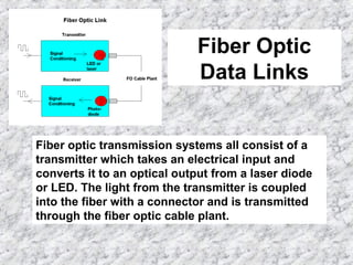
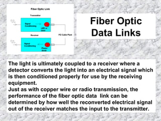
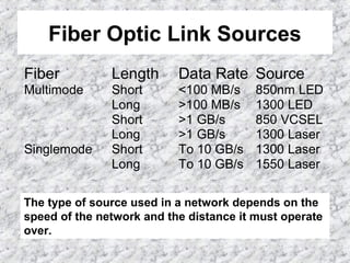
FIBER OPTIC BASICS
Part 4 – Fiber Optic Links
Fiber Optic
Data Links
Fiber optic transmission systems all consist of a
transmitter which takes an electrical input and
converts it to an optical output from a laser diode
or LED. The light from the transmitter is coupled
into the fiber with a connector and is transmitted
through the fiber optic cable plant.
Fiber Optic
Data Links
The light is ultimately coupled to a receiver where a
detector converts the light into an electrical signal which
is then conditioned properly for use by the receiving
equipment.
Just as with copper wire or radio transmission, the
performance of the fiber optic data link can be
determined by how well the reconverted electrical signal
out of the receiver matches the input to the transmitter.
Fiber Optic Link Sources
Fiber Length Data Rate Source
Multimode Short <100 MB/s 850nm LED
Long >100 MB/s 1300 LED
Short >1 GB/s 850 VCSEL
Long >1 GB/s 1300 Laser
Singlemode Short To 10 GB/s 1300 Laser
Long To 10 GB/s 1550 Laser
The type of source used in a network depends on the
speed of the network and the distance it must operate
over.
Fiber Optic Link Sources
LEDs are useful to only several hundred megabits per
second, so they are used in slower systems. Lasers
can be used up to 10 gigabits per second or more,
so they are the source of choice in high speed
networks.
Since the loss of the fiber goes down with longer
wavelengths, long distance links tend to use the
longest wavelength sources.
Fiber Optic Link Power Budget
After a fiber optic cable plant is installed, it may be
used with a number of different types of fiber optic
networks. Computer networks, telephone signals,
video links, and even audio can be sent on the
installed fibers. Each network type has a requirement
for the performance of the fiber optic cable link. Most
simply specify the maximum loss in the link that can
be tolerated, a function of component specifications
and installation quality. Others also specify the
bandwidth performance of the fiber which is
determined by the specifications of the fiber chosen.
Fiber Optic Link Power Budget
Every fiber optic link has a maximum loss of a link
over which it can work. That loss is determined by the
output power of the transmitter coupled into the fiber
and the sensitivity of the receiver, all expressed in
dB.. The loss of the fiber optic cable it uses must be
less than 1that maximum loss for proper operation.
While every link installed must meet some maximum
loss to allow operation of the network intended to use
it, different networks may have different link margins.
Therefore we use a different approach. The loss of the
link is considered acceptable if it is less than
standard maximum values calculated from the
characteristics of the link installation.
Fiber Optic Link Power Budget
What causes the losses in the fiber optic cable? First
the fiber itself. The next loss factor is terminations.
Splices are common in singlemode but rare in
multimode networks Singlemode fiber is usually
spliced with a fusion splicer which welds the two
fibers together in an electric arc, with much lower
losses.
The final loss factor is stress in installation. Fiber
optic cable pulled with too much tension may be
damaged. Each time you make a bend with a fiber
optic cable, you put some stress in the fiber which
can cause loss. Even cable ties tightened on the cable
can cause loss. Stress loss should be zero!
Fiber Optic Link
Performance
The ability of any fiber optic system to transmit data ultimately
depends on the optical power at the receiver as shown in this
graph ,which shows the data link bit error rate as a function of
optical power at the receiver. Either too little or too much power
will cause high bit error rates. Too much power, and the
receiver amplifier saturates, too little and noise becomes a
problem. This receiver power depends on two basic factors:
how much power is launched into the fiber by the transmitter
and how much is lost by attenuation in the optical fiber cable
that connects the transmitter and receiver.

Fiber optics 1-4

  • 1.
    FIBER OPTIC BASICS Part4 – Fiber Optic Links
  • 2.
    Fiber Optic Data Links Fiberoptic transmission systems all consist of a transmitter which takes an electrical input and converts it to an optical output from a laser diode or LED. The light from the transmitter is coupled into the fiber with a connector and is transmitted through the fiber optic cable plant.
  • 3.
    Fiber Optic Data Links Thelight is ultimately coupled to a receiver where a detector converts the light into an electrical signal which is then conditioned properly for use by the receiving equipment. Just as with copper wire or radio transmission, the performance of the fiber optic data link can be determined by how well the reconverted electrical signal out of the receiver matches the input to the transmitter.
  • 4.
    Fiber Optic LinkSources Fiber Length Data Rate Source Multimode Short <100 MB/s 850nm LED Long >100 MB/s 1300 LED Short >1 GB/s 850 VCSEL Long >1 GB/s 1300 Laser Singlemode Short To 10 GB/s 1300 Laser Long To 10 GB/s 1550 Laser The type of source used in a network depends on the speed of the network and the distance it must operate over.
  • 5.
    Fiber Optic LinkSources LEDs are useful to only several hundred megabits per second, so they are used in slower systems. Lasers can be used up to 10 gigabits per second or more, so they are the source of choice in high speed networks. Since the loss of the fiber goes down with longer wavelengths, long distance links tend to use the longest wavelength sources.
  • 6.
    Fiber Optic LinkPower Budget
  • 7.
    Fiber Optic LinkPower Budget After a fiber optic cable plant is installed, it may be used with a number of different types of fiber optic networks. Computer networks, telephone signals, video links, and even audio can be sent on the installed fibers. Each network type has a requirement for the performance of the fiber optic cable link. Most simply specify the maximum loss in the link that can be tolerated, a function of component specifications and installation quality. Others also specify the bandwidth performance of the fiber which is determined by the specifications of the fiber chosen.
  • 8.
    Fiber Optic LinkPower Budget Every fiber optic link has a maximum loss of a link over which it can work. That loss is determined by the output power of the transmitter coupled into the fiber and the sensitivity of the receiver, all expressed in dB.. The loss of the fiber optic cable it uses must be less than 1that maximum loss for proper operation. While every link installed must meet some maximum loss to allow operation of the network intended to use it, different networks may have different link margins. Therefore we use a different approach. The loss of the link is considered acceptable if it is less than standard maximum values calculated from the characteristics of the link installation.
  • 9.
    Fiber Optic LinkPower Budget What causes the losses in the fiber optic cable? First the fiber itself. The next loss factor is terminations. Splices are common in singlemode but rare in multimode networks Singlemode fiber is usually spliced with a fusion splicer which welds the two fibers together in an electric arc, with much lower losses. The final loss factor is stress in installation. Fiber optic cable pulled with too much tension may be damaged. Each time you make a bend with a fiber optic cable, you put some stress in the fiber which can cause loss. Even cable ties tightened on the cable can cause loss. Stress loss should be zero!
  • 10.
    Fiber Optic Link Performance Theability of any fiber optic system to transmit data ultimately depends on the optical power at the receiver as shown in this graph ,which shows the data link bit error rate as a function of optical power at the receiver. Either too little or too much power will cause high bit error rates. Too much power, and the receiver amplifier saturates, too little and noise becomes a problem. This receiver power depends on two basic factors: how much power is launched into the fiber by the transmitter and how much is lost by attenuation in the optical fiber cable that connects the transmitter and receiver.