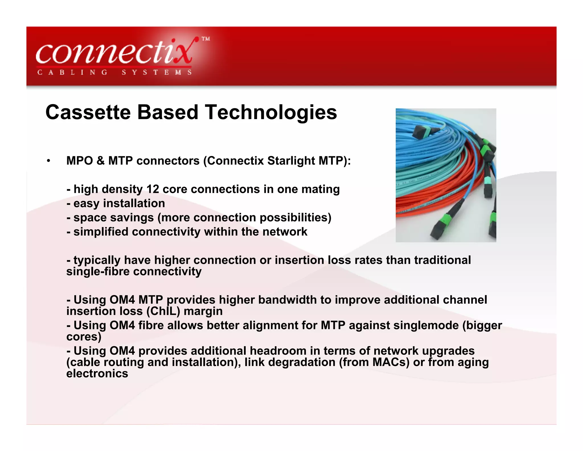
Data Centre Environments
CCS Commercial Overview - Session 2
Optical Fibre in the Data Centre


4th December 2008
Paul Mathews MInstSMM
Global Channel Manager
Introduction to Data Centres
•    The heartbeat of any business, designed to manage the flow, processing and
     storage of information

•    Must be reliable, secure and flexible to enable growth and reconfiguration

•    A data centre can support small singular businesses through to thousands of
     clients ecommerce facilities

•    “A building or portion of a building whose primary function is to house a
     computer room and its support areas,” according to TIA 942
What created the demand for Data Centres

•   Data storage and record keeping

•   Bandwidth hungry applications on the internet such as video

•   E-commerce required 24-7

•   Online learning

•   Supercomputing applications
Data Centre Dynamics

1.0    Physical location of the data centre
2.0    Physical sizing and capabilities
3.0    Electrical systems to and within the data centre
4.0    Fire minimisation, detection, alarm and suppression
5.0    Heating, Ventilation and Air Conditioning (HVAC)
6.0    Communications Cabling within and to the data centre
7.0    Cabling containment within the data centre (including
       raised floors)
8.0    Equipment racks and cabinets
9.0    Information Technology equipment
10.0   Security, Access and CCTV
11.0   Project management
12.0   Ongoing maintenance
Current and future trends driving data centres

•   Government data warehousing legislation

•   Medical and Financial Industries

•   Redundancy against catastrophic loss (natural disaster / terrorism)

•   Faster Data Centres and Storage Area Networks (SAN)

•   Speeds of 40Gb/s and 100Gb/s depending on the application
Why specify optical fibre?

•   Low loss and high bandwidth

•   Small size – high density and compact

•   Lower power consumption

•   Lower generation of heat
Network Architecture

•   Enterprise networks are moving towards 10Gbs optical fibre backbone to
    support 1Gbs copper/fibre horizontal links

•   Star topology still dominant infrastructure design

•   Trends are changing towards Fibre-To-The-Enclosure (FTTE) because of
    extended performance capabilities with fibre closer to the workstation

•   Data Centre LANs are moving towards optical fibre because of the amount of
    data being stored, processed and managed


•   A Data Centre typically consists of bank of server racks, connected to the
    SAN on one side and the Intranet for LANs and Internet links for the world
    wide web on another
Network Protocols – Computer Room LAN

•   Switches and Servers typically transmit Ethernet – currently 10Gbs is the top
    speed:

    IEEE 802.3an 10GBASE-T Copper (published 2006)
    IEEE 802.3ae 10GBASE-F Optical Fibre (published 2002)

•   IEEE is currently working on standards for Ethernet 40Gbs and 100Gbs

•   IEEE identifies standards for transceiver port types and the requirements and
    characteristics of the physical layer
Network Protocols – Storage Area Network

•   Within the SAN area of a Data Centre – Fibre Channel is the popular protocol,
    transmitting top speeds as:

    2GFC, 4GFC, 8GFC – next focus is 16GFC

•   Base2 speeds have doubled in speed each time standards have been
    publishing

•   Fibre Channel also uses Base10 for inter-switch links and core connections
    (10GFC was published just as 10GBaseT, incorporating serial vertical cavity
    surface emitting laser technology – VCSEL – max distance 300m on OM3)

•   Fibre Channel is now looking towards 20GFC and 40GFC as Base10 speeds
Multimode fibre benefits

•   Longer lifespan than copper – as looking ahead at 40Gbs and 100Gbs looks
    like copper will only support short distances – 10m approx

•   Singlemode fibre has very high bandwidth but requires advanced
    optoelectronics for transmission (approx 25-30% higher)

•   40Gbs and 100Gbs transmissions can be achieved on distances of 200-300m
    on OM3 optical fibre

•   OM3 laser-optimised fibre, OM4 extended length laser-optimised fibre

•   Optical fibre differences between multimode and singlemode are (relating to
    cost differences) explained on the next slide:

    1) Wavelength of operation
    2) Size of the optical fibre core where light is carried
Multimode or Singlemode in the Data Centre?

•   Materials transmitting long wavelengths of 1310nm and 1550nm cost more
    than short distance 850nm lasers

                                      +

•   Transceivers used to connect singlemode transmissions require tighter
    alignment tolerances to couple, or capture light. Singlemode fibre core is
    much smaller (9um)

                                      +

•   Singlemode optical fibre equipment consists of high-precision transceivers,
    tighter tolerance connectors and careful cable installation and termination

                                      =

•   Considerable costs compared to multimode fibre for data centres
Optical Fibre Technologies

•   Where optical fibre is installed in today’s data centres, 70% is OM3 or OM4
    grade

•   Vertical cavity surface emitting lasers (VCSEL) are the laser source for
    transmission on OM3 and OM4

•   Reduced differential mode delay (DMD) on OM3 and OM4; controlled core
    ensures 10Gbs on low-cost 850nm serial applications

•   OM3 supports 10Gbs up to 300m
•   OM4 supports 10Gbs up to 550m

•   OM4 is recommended for longer distances such as large building backbones,
    medium length campus backbones and/or sensitive power budget
    applications such as data centres

•   OM4 will eliminate DMD in the fibre and will have a bandwidth of
    4700MHz.km; more than double the requirement for IEEE 10Gbs 300m
    support
Cassette Based Technologies

•   MPO & MTP connectors (Connectix Starlight MTP):

    - high density 12 core connections in one mating
    - easy installation
    - space savings (more connection possibilities)
    - simplified connectivity within the network

    - typically have higher connection or insertion loss rates than traditional
    single-fibre connectivity

    - Using OM4 MTP provides higher bandwidth to improve additional channel
    insertion loss (ChIL) margin
    - Using OM4 fibre allows better alignment for MTP against singlemode (bigger
    cores)
    - Using OM4 provides additional headroom in terms of network upgrades
    (cable routing and installation), link degradation (from MACs) or from aging
    electronics
Power Consumption – Copper v Optical Fibre

•   Today’s data centres are over sized, consume too much power and waste
    money on cooling

•   Optical fibre has power savings over copper:

    10GBASE-T transceiver uses approx 6 Watts (W) of power
    10GBASE-SR transceiver uses less than 1 W to transmit the same signal

    Optical fibre saves 5 W of power with each connection

•   Major data centres consists of 10,000+ connections:

    10,000 x 5 W = 50 kW
Cooling - General Guidelines

•   The power used by transceivers is dissipated as heat – which
    is removed from the computer room by cooling (CRAC units)

•   CRAC units efficiency rating is 10 W (so 10W of power are
    used to remove 1W of heat)

•   Efficiency of air condition varies from 3:1 to 1:1, i.e it takes
    between 300W and 1000W of electricity to remove 1kW of heat
    with air conditioning

•   Improving Cooling and Airflow – Connectix Article 14
    http://www.connectixcablingsystems.com/library/detail.cfm?it
    em=83
Future proofing cabling in Data Centres

•   IEEE is currently developing 802.3ba 40Gbs and 100Gbs aimed at:

    40Gbs – server links
    100Gbs – core switching and routing applications

•   IEEE 802.3ba also offers parallel optical fibre technology (using 4 or 10
    VCSELs and detectors over optical fibres for 40Gbs or 100Gbs respectively)

•   Delay SKEW (the difference in time between one signal on a fibre adjacent to
    other cores in the cable) compensation is managed within transceiver
    circuitry
Design considerations for Data Centre cabling

•   System migration to higher speeds of 40Gbs and 100Gbs

•   Performance and reliability needed on 10Gbs transmissions – headroom, this
    can be achieved by:

    Using higher bandwidth cable to reduce intersymbol interference (ISI); occurs
    when bits of data run together

    Specifying lower loss connectors which improve headroom margin

    Specifying optical fibre rated for longer distance than will be used (OM3 and
    OM4)
Data Centre Whitepapers
•   Data Centre Design Whitepaper
    http://www.connectixcablingsystems.com/library/detail.cfm?item=10
Connectix Technical Articles

•   Log on to www.connectixcablingsystems.com for full access to our data
    centre and high speed LAN support articles

•   Log on to www.connectixcablingsystems.com/events for details of our Data
    Centre Design Principle Seminars run in association with The IET


IET Endorsed
                    CIBSE Continuing
Training            Professional Development        BICSI Continuing Education Credits
provider

Commercial Overview DC Session 2 Optical Fibre In The Data Centre

  • 1.
    Data Centre Environments CCSCommercial Overview - Session 2 Optical Fibre in the Data Centre 4th December 2008 Paul Mathews MInstSMM Global Channel Manager
  • 2.
    Introduction to DataCentres • The heartbeat of any business, designed to manage the flow, processing and storage of information • Must be reliable, secure and flexible to enable growth and reconfiguration • A data centre can support small singular businesses through to thousands of clients ecommerce facilities • “A building or portion of a building whose primary function is to house a computer room and its support areas,” according to TIA 942
  • 3.
    What created thedemand for Data Centres • Data storage and record keeping • Bandwidth hungry applications on the internet such as video • E-commerce required 24-7 • Online learning • Supercomputing applications
  • 4.
    Data Centre Dynamics 1.0 Physical location of the data centre 2.0 Physical sizing and capabilities 3.0 Electrical systems to and within the data centre 4.0 Fire minimisation, detection, alarm and suppression 5.0 Heating, Ventilation and Air Conditioning (HVAC) 6.0 Communications Cabling within and to the data centre 7.0 Cabling containment within the data centre (including raised floors) 8.0 Equipment racks and cabinets 9.0 Information Technology equipment 10.0 Security, Access and CCTV 11.0 Project management 12.0 Ongoing maintenance
  • 5.
    Current and futuretrends driving data centres • Government data warehousing legislation • Medical and Financial Industries • Redundancy against catastrophic loss (natural disaster / terrorism) • Faster Data Centres and Storage Area Networks (SAN) • Speeds of 40Gb/s and 100Gb/s depending on the application
  • 6.
    Why specify opticalfibre? • Low loss and high bandwidth • Small size – high density and compact • Lower power consumption • Lower generation of heat
  • 7.
    Network Architecture • Enterprise networks are moving towards 10Gbs optical fibre backbone to support 1Gbs copper/fibre horizontal links • Star topology still dominant infrastructure design • Trends are changing towards Fibre-To-The-Enclosure (FTTE) because of extended performance capabilities with fibre closer to the workstation • Data Centre LANs are moving towards optical fibre because of the amount of data being stored, processed and managed • A Data Centre typically consists of bank of server racks, connected to the SAN on one side and the Intranet for LANs and Internet links for the world wide web on another
  • 8.
    Network Protocols –Computer Room LAN • Switches and Servers typically transmit Ethernet – currently 10Gbs is the top speed: IEEE 802.3an 10GBASE-T Copper (published 2006) IEEE 802.3ae 10GBASE-F Optical Fibre (published 2002) • IEEE is currently working on standards for Ethernet 40Gbs and 100Gbs • IEEE identifies standards for transceiver port types and the requirements and characteristics of the physical layer
  • 9.
    Network Protocols –Storage Area Network • Within the SAN area of a Data Centre – Fibre Channel is the popular protocol, transmitting top speeds as: 2GFC, 4GFC, 8GFC – next focus is 16GFC • Base2 speeds have doubled in speed each time standards have been publishing • Fibre Channel also uses Base10 for inter-switch links and core connections (10GFC was published just as 10GBaseT, incorporating serial vertical cavity surface emitting laser technology – VCSEL – max distance 300m on OM3) • Fibre Channel is now looking towards 20GFC and 40GFC as Base10 speeds
  • 10.
    Multimode fibre benefits • Longer lifespan than copper – as looking ahead at 40Gbs and 100Gbs looks like copper will only support short distances – 10m approx • Singlemode fibre has very high bandwidth but requires advanced optoelectronics for transmission (approx 25-30% higher) • 40Gbs and 100Gbs transmissions can be achieved on distances of 200-300m on OM3 optical fibre • OM3 laser-optimised fibre, OM4 extended length laser-optimised fibre • Optical fibre differences between multimode and singlemode are (relating to cost differences) explained on the next slide: 1) Wavelength of operation 2) Size of the optical fibre core where light is carried
  • 11.
    Multimode or Singlemodein the Data Centre? • Materials transmitting long wavelengths of 1310nm and 1550nm cost more than short distance 850nm lasers + • Transceivers used to connect singlemode transmissions require tighter alignment tolerances to couple, or capture light. Singlemode fibre core is much smaller (9um) + • Singlemode optical fibre equipment consists of high-precision transceivers, tighter tolerance connectors and careful cable installation and termination = • Considerable costs compared to multimode fibre for data centres
  • 12.
    Optical Fibre Technologies • Where optical fibre is installed in today’s data centres, 70% is OM3 or OM4 grade • Vertical cavity surface emitting lasers (VCSEL) are the laser source for transmission on OM3 and OM4 • Reduced differential mode delay (DMD) on OM3 and OM4; controlled core ensures 10Gbs on low-cost 850nm serial applications • OM3 supports 10Gbs up to 300m • OM4 supports 10Gbs up to 550m • OM4 is recommended for longer distances such as large building backbones, medium length campus backbones and/or sensitive power budget applications such as data centres • OM4 will eliminate DMD in the fibre and will have a bandwidth of 4700MHz.km; more than double the requirement for IEEE 10Gbs 300m support
  • 13.
    Cassette Based Technologies • MPO & MTP connectors (Connectix Starlight MTP): - high density 12 core connections in one mating - easy installation - space savings (more connection possibilities) - simplified connectivity within the network - typically have higher connection or insertion loss rates than traditional single-fibre connectivity - Using OM4 MTP provides higher bandwidth to improve additional channel insertion loss (ChIL) margin - Using OM4 fibre allows better alignment for MTP against singlemode (bigger cores) - Using OM4 provides additional headroom in terms of network upgrades (cable routing and installation), link degradation (from MACs) or from aging electronics
  • 14.
    Power Consumption –Copper v Optical Fibre • Today’s data centres are over sized, consume too much power and waste money on cooling • Optical fibre has power savings over copper: 10GBASE-T transceiver uses approx 6 Watts (W) of power 10GBASE-SR transceiver uses less than 1 W to transmit the same signal Optical fibre saves 5 W of power with each connection • Major data centres consists of 10,000+ connections: 10,000 x 5 W = 50 kW
  • 15.
    Cooling - GeneralGuidelines • The power used by transceivers is dissipated as heat – which is removed from the computer room by cooling (CRAC units) • CRAC units efficiency rating is 10 W (so 10W of power are used to remove 1W of heat) • Efficiency of air condition varies from 3:1 to 1:1, i.e it takes between 300W and 1000W of electricity to remove 1kW of heat with air conditioning • Improving Cooling and Airflow – Connectix Article 14 http://www.connectixcablingsystems.com/library/detail.cfm?it em=83
  • 16.
    Future proofing cablingin Data Centres • IEEE is currently developing 802.3ba 40Gbs and 100Gbs aimed at: 40Gbs – server links 100Gbs – core switching and routing applications • IEEE 802.3ba also offers parallel optical fibre technology (using 4 or 10 VCSELs and detectors over optical fibres for 40Gbs or 100Gbs respectively) • Delay SKEW (the difference in time between one signal on a fibre adjacent to other cores in the cable) compensation is managed within transceiver circuitry
  • 17.
    Design considerations forData Centre cabling • System migration to higher speeds of 40Gbs and 100Gbs • Performance and reliability needed on 10Gbs transmissions – headroom, this can be achieved by: Using higher bandwidth cable to reduce intersymbol interference (ISI); occurs when bits of data run together Specifying lower loss connectors which improve headroom margin Specifying optical fibre rated for longer distance than will be used (OM3 and OM4)
  • 18.
    Data Centre Whitepapers • Data Centre Design Whitepaper http://www.connectixcablingsystems.com/library/detail.cfm?item=10
  • 19.
    Connectix Technical Articles • Log on to www.connectixcablingsystems.com for full access to our data centre and high speed LAN support articles • Log on to www.connectixcablingsystems.com/events for details of our Data Centre Design Principle Seminars run in association with The IET IET Endorsed CIBSE Continuing Training Professional Development BICSI Continuing Education Credits provider