Network engg
•
2 likes•781 views

this is a complete notes of N+ network engg.which are very useful while submitting project reports which are provided by the technical zone...

Recommended
More Related Content
What's hot
What's hot (20)
Viewers also liked
Viewers also liked (11)
Similar to Network engg
Similar to Network engg (20)
Recently uploaded
Recently uploaded (20)
Network engg
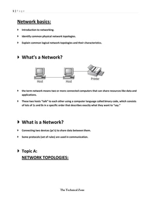
- 1. 1|Page Network basics: Introduction to networking. Identify common physical network topologies. Explain common logical network topologies and their characteristics. What’s a Network? the term network means two or more connected computers that can share resources like data and applications. These two hosts “talk” to each other using a computer language called binary code, which consists of lots of 1s and 0s in a specific order that describes exactly what they want to “say.” What is a Network? Connecting two devices (pc’s) to share data between them. Some protocols (set of rules) are used in communication. Topic A: NETWORK TOPOLOGIES:
- 2. 2|Page POINT TO POINT BUS TOPOLOGY STAR TOPOLOGY RING TOPOLOGY
- 3. 3|Page Mesh topology Hybrid topology Hierarchical topology
- 4. 4|Page Classification of network: Metropolitan areanetwork (MAN). Wide areanetwork (WAN).
- 5. 5|Page Network Architecture: Peer-to-Peer Client/Server In peer-to-peer networks do not have any central. In peer-to-peer networks do not have any central. All users are equal. Meaning that when it comes to authority, they’re all equals. If your network is running Windows, Mac, or Unix in a local LAN workgroup, you have a peer-to-peer network. Example of peer to peer network:- Client/Server networks: A single server is specified that uses a network operating system for managing the whole network. Client machine’s request for a resource goes to the main server.
- 6. 6|Page Topologies types: Physical topology: the physical presence of a Ethernet cable in a topology. Logical topology: when data sharing starts through the physical Ethernet cable in a topology.
- 7. 7|Page Categorize standard cable types and their properties CABLE STANDARDS: Ethernet cable Cable type max txn distance Max speed Notes 10 baseT UTP 100m 10mbps One of the most popular network cabling schemes. 10baseFL MMF 2000m 10mbps Ethernet over fiber optics to the desktop. 100baseT UTP Exceeds100m 100mbps Four pairs of Category 5e or higher 100baseTx UTP 100m 100-200mbps 100baseT4 UTP 100m 33mbps each 100baseFx MMF 412m,2000m 100mbps 100Mbps Ethernet over fiber optics 1000baseSx MMF 550m 1000mbps Uses SC fiber connectors. Max length depends on fiber size.
- 8. 8|Page 1000baseCx Balanced 25m 1000mbps Uses a special connector, shielded copper the HSSDC 1000baseLx Mmf & Smf 550mmf/2000mmf 1000mbps Uses longer wavelength laser than 1000Base-SX. Uses SC and LC connectors. 10GbaseT UTP 100m 10Gbps Connects to the network like a Fast Ethernet link using UTP. 10GbaseSr Mmf 300m 10Gbps 850 nm laser. Max length depends on fiber size and quality. 10GbaseLr Smf 10km 10Gbps 1310 nm laser. Max length depends on fiber size and quality. 10baseEr Smf 40km 10Gbps 1550 nm laser. Max length depends on fiber size and quality Ethernet cable Cable type max txn distance Max speed Notes 10base5 coax 500m 10mbps Also called Thicknet, this cable type uses vampire taps to connect
- 9. 9|Page devices to cable. 10base2 coax 185m 10mbps Also called Thinnet, a very popular implementation of Ethernet Rollover cable UTP 20m 10mbps Used to config routers, form a host to a console serial comm port. Wiring Standards: Straight-through cable (568A) Crossover cable (568B) Rolled cable (rollover) Straight-through cable (568A) Crossover cable (568B)
- 10. 10 | P a g e Rolled cable (rollover) Cable tester Co-axial cables: Thinnet (10base2): Its txn rate is 10mbps up to range of 200m,mainly used in small n/w’s. used to send data to longer distances. Thicknet(10base5): It specifies for thick coaxial cable carrying Ethernet signals. it ranges up to 500m and 1cm thick and is used for the original Ethernet n/w’s because of extra thickness it is protected from the moisture to reach at the core.
- 11. 11 | P a g e Ethernet Cable Descriptions: CAT-1: Two twisted wire pairs (four wires). Used in POTS, before 1983, this was the standard cable used throughout the North American telephone system. POTS cable still exists in parts of the Public Switched Telephone Network (PSTN) andsupports signals limited to the 1MHz frequency range. CAT-2: Four twisted wire pairs (eight wires). It handles up to 4Mbps, with a frequency limitation of 10MHz, and is now obsolete. CAT-3: Four twisted wire pairs (eight wires) with three twists per foot. This type can handle transmissions up to 16MHz. It was popular in the mid-1980s for up to 10Mbps Ethernet or 4Mbps token ring n/w’s Physical Media Coaxial Twisted pair
- 12. 12 | P a g e Fiber optic RS-232 USB port Patch panel MEDIA CONNECTORS: RJ-11: The connector used with UTP cable is called RJ-11 for phones that use 2pairs four wires. RJ-45:The connector used with UTP cable is called RJ-45 has four pairs (eight wires),
- 13. 13 | P a g e ST: the two most popular are the straight tip (ST) and subscriber (or square) connector (SC). The ST fiber-optic connector (developed by AT&T) is one of the most widely used fiber-optic connectors. SC: THE SC connector is another type of fiber-optic connector. SC connectors are latched—a mechanism holds the connector in securely and prevents it from falling out. LC: It is easier to terminate. It uses a ceramic insert just as standard-sized fiber-optic connectors do. MT-RJ:The MT-RJ fiber-optic connector was the first small form factor fiber-optic connector to be widely used, and it’s only one-third the size of the SC and ST connectors it most often replaces. Serial Cables:RS-232:Recommended Standard 232 (RS-232) was a cable standard commonly used for serial data signals connecting data-terminal equipment and data-communications equipment, as when you connect a computer’s serial port to an external modem. Universal Serial Bus (USB):It is now the built-in serial bus. We use USB to connect printers, scanners, and a host of other input devices like keyboards,joysticks, and mice. PROPERTIES OF CABLES:The reason we use so many different types of cables in a network is that each type has its own set of properties that specifically make it the best to use for a particular area or purpose. Different types vary in transmission speeds, distance, duplex, noise immunity, and frequency. Transmission Speeds: Distance: Duplex: Noise Immunity: Frequency:
- 14. 14 | P a g e NETWORKING DEVICES HUB: A hub is the device that connects all the segments of the network together. Any transmission received on one port will be sent out all the other ports in the hub, including the receiving pair for the transmitting device, Techniques used in hub are: CSMA/CD: CSMA/CA: TYPES OF HUBS: ACTIVE PASSSIVE REPEATER: This configuration will provide an extension to your Ethernet segment and give you a gain of another 100 meters. MODEM: A modem is a device that modulates digital data onto an analog carrier for transmission over an analog medium and then demodulates from the analog carrier to a digital signal again at the receiving end. Traditional (plain old telephone service [POTS])
- 15. 15 | P a g e DSL Cable TYPES OF MODEMS: Internal. External. Network Interface Card (NIC):A Network Interface Card (NIC) is installed in your computer to connect, or interface, your computer to the network. It provides the physical, electrical, and electronic connections to the network media. Transceiver (Media Converter): Another small device that you might come across on a network is an external transceiver, otherwise known as a media converter. These simple
- 16. 16 | P a g e devices allow a NIC or other networking device to connect to a different type of media than it was designed to connect to. Many hubs, switches, and NICs have special connectors that allow for this. For instance, let’s say you’ve got a 100Base-TX switch. Dix to rj-45 connecter 100basetx to 100basefx connecter Bridge: A bridge—specifically, a transparent bridge—is a network device that connects two similar network segments together. Its primary function is to keep traffic separated on either side of the bridge
- 17. 17 | P a g e Switch: A switch recognizes frames and pays attention to the source and destination MAC address of the incoming frame as well as the port on which it was received. TYPES OF SWITCHES: ATM SWITCHES. LAN SWITCHES. WAN SWITCHES. Wireless Access Point (WAP): A wireless access point (AP) allows mobile users to connect to a wired network wirelessly via radio frequency technologies. Using wireless technologies. Basically the wireless equivalent of hubs or switches because they can connect multiple wireless (and often wired) devices together to form a network.
- 18. 18 | P a g e Router: A router is a network device used to connect many, sometimes disparate, network segments together, combining them into what we call an internetwork. A well-configured router can make intelligent decisions about the best way to get network data to its destination. Firewall: Basically, firewalls are your network’s security guards; and to be real, they’re probably the most important thing to implement on your network.
- 19. 19 | P a g e Dynamic Host Configuration Protocol (DHCP) Server: A DHCP is a server, which used a pool, which serves randomly IP addresses to the clients by broadcasting. CSU/DSU: The channel service unit (CSU) terminates the line at the customer’s premises and also provides diagnostics and remote testing, if necessary. The Data Service Unit (DSU) does the actual transmission of the signal through the CSU and can also provide buffering and data-flow control.
- 20. 20 | P a g e Multilayer Switch: A multilayer switch (MLS) is a computer networking device. Domain Name Service (DNS) Server: A Domain Name Service (DNS) server is one of the most important servers in your network and on the Internet as well. Because without a DNS server, you would have to type http://206.123.114.186 instead of simply entering www.iiht.com. So it follows that you can pretty much think of a DNS server as the phone book of the Internet. Proxy Server: A proxy server is basically a type of server that handles its client-machine requests by forwarding them on to other servers while allowing granular control over the traffic between the local LAN and the Internet.
- 21. 21 | P a g e OSI MODEL(REFERENCE MODEL): Internetworking Models: When networks first came into being, computers could usually communicate only with computers from the same manufacturer. For example, companies ran either a complete DECnet solution or an IBM solution—not both together. In the late 1970s, the Open Systems Interconnection (OSI) reference model was created by the International Organization for Standardization (ISO) to break through this barrier. The OSI model was meant to help vendors create interoperable network device and software in the form of protocols so that different vendor networks could word with each other. Like world peace, it’ll probably never happen completely, but it’s still a great goal. The Layered Approach: Advantages of Reference Models: It divides the network communication process into smaller and simpler components, It allows multiple-vendor development through standardization of network components It encourages industry standardization by defining what functions occur at each layer of the model. It allows various types of network hardware and software to communicate. It prevents changes in one layer from affecting other layers, so it doesn’t hamper development and makes application programming easier.
- 22. 22 | P a g e The OSI Reference Model Application (Layer 7) Presentation (Layer 6) Session (Layer 5) Transport (Layer 4) Network (Layer 3) Data Link (Layer 2) Physical (Layer 1)
- 23. 23 | P a g e PHYSICAL LAYER: (layer 1) The Physical layer specifies the electrical, mechanical, procedural, and functional requirements for activating, maintaining, and deactivating a physical link between end systems. Physical layer :which does two important things: I. It sends and receivesbits (0 & 1) through the physical cable. II. It simply connect devices physically. III. Like: utp, stp, co-axial cable and etc. IV. PHYSICAL the physical layer deals with the physical characteristics of the transmission medium. It defines the electrical, mechanical, procedural, and functional specifications for activating, maintaining, and deactivating the physical link between end systems. Such characteristics as voltage levels, timing of voltage changes, physical data rates, maximum transmission distances, physical connectors, and other similar attributes are defined by physical layer specifications. Examples :- EIA/TIA-232, RJ45, NRZ. DATA LINK LAYER (LAYER 2): The data link layer formats the message into pieces, each called a data frame, and adds a customized header containing the destination and source hardware address. Encapsulation used in L2 devices is FRAMES. In L2 devices, two types has two sub-layers : 1. Media Access Control (MAC). 2. Logical Link Control (LLC).
- 24. 24 | P a g e NETWORK LAYER(Layer 3): NETWORK LAYER: The Network layer manages device-addressing, tracks the location of devices on the network, and determines the best way to move data, which means that the Network layer must transport traffic between devices that aren’t locally attached. There are two subtypes in L3: (Data packets): 1. IPV4. 2. IPV6. Route-update packets: Protocols that send route-update packets are called routing protocols. FOR EX: Routing Information Protocol (RIP), RIPv2, Enhanced Interior Gateway Routing Protocol (EIGRP), and Open Shortest Path First (OSPF). Network addresses: routing table. Interface :This is the exit interface a packet will take when destined for a specific network. Metric This value equals the distance to the remote network.
- 25. 25 | P a g e THE TRANSPORT LAYER(LAYER 4): They provide end-to-end data transport services and can establish a logical connection between the sending host and destination host on an internetwork. The Transport layer is responsible for providing mechanisms for multiplexing upper layer applications, establishing sessions, and tearing down virtual circuits. Two types of transport layer which are: 1. TCP protocol: reliable connection 2. UDP protocol: unreliable connection.
- 26. 26 | P a g e Connection-Oriented Communication: Before a transmitting host starts to send segments down the model, the sender’s TCP process contacts the destination’s TCP process to establish a connection. What is created is known as a virtual circuit. This type of communication is called connection-oriented. Flow Control: Data integrity is ensured at the Transport layer by maintaining flow control and by allowing users to request reliable data transport between systems. Flow control provides a means for the receiver to govern the amount of data sent by the sender. It prevents a sending host on one side of the connection from overflowing the buffers in the receiving host—an event that can result in lost data.
- 27. 27 | P a g e Windowing: Data throughput happens quickly and efficiently. And as you can imagine, it would be slow if the transmitting machine had to wait for an acknowledgment after sending each segment. But because time is available after the sender transmits the data segment and before it finishes processing acknowledgments from the receiving machine, the sender uses the break as an opportunity to transmit more data.
- 28. 28 | P a g e Acknowledgments: It guarantees that the data won’t be duplicated or lost. This is achieved through something called positive acknowledgment with retransmission—a technique that requires a receiving machine to communicate with the transmitting source by sending an acknowledgment message back to the sender when it receives data.
- 29. 29 | P a g e The Session Layer (layer 6): The Session layer is responsible for setting up, managing, and then tearing down sessions between Presentation-layer entities. This layer also provides dialogue control between devices, or nodes. It coordinates communication between systems and serves to organize their communication by offering three different modes: simplex, half duplex, and full duplex. To sum up, the Session layer basically keeps applications’ data separate from other applications’ data. It simply use to keep the data different from each other to be mingled easily. It used to reach data reliably to the clients in a proper and safe way. The Presentation Layer (layer 6): The Presentation layer gets its name from its purpose: It presents data to the Application layer and is responsible for data translation and code formatting. This layer is essentially a translator and provides coding and conversion functions. A successful data-transfer technique is to adapt the data into a standard format before transmission. Computers are configured to receive this generically formatted data and then convert the data back into its native format for reading (for example, EBCDIC to ASCII). By providing translation services, the Presentation layer ensures that data transferred from one system’s Application layer can be read by the Application layer of another one. For ex: data compression, decompression, encryption, and decryption are associated With this layer.
- 30. 30 | P a g e The Application layer(layer 7): The Application layer of the OSI model marks the spot where users actually communicate to the computer. Often, they unite communicating components from more than one network application. Prime examples are file transfers and email, as well as enabling remote access, network- management activities, client/server processes like printing, and information location. For ex: internet explorer (ie), Mozilla fire fox, opera browser, safari and so on.
- 31. 31 | P a g e IP TERMINOLOGY… Bit : A bit is one digit, either a 1 or a 0. Byte : A byte is 7 or 8 bits, depending on whether parity is used. For the rest of this chapter, always assume a byte is 8 bits. Octet : An octet, made up of 8 bits, is just an ordinary 8-bit binary number. In this chapter, the terms byte and octet are completely interchangeable. Network address : This is the designation used in routing to send packets to a remote network—for example, 10.0.0.0, 172.16.0.0, and 192.168.10.0. Broadcast address : The broadcast address is used by applications and hosts to send information to all hosts on a network. Examples include 255.255.255.255, which designates all networks and all hosts; 172.16.255.255, which specifies all subnets and hosts on network 172.16.0.0; and 10.255.255.255, which broadcasts to all subnets and hosts on network 10.0.0.0. The Hierarchical IP Addressing Scheme An IP address consists of 32 bits of information. These bits are divided into four sections, referred to as octets or bytes, and four octets sum up to 32 bits (8×4=32). You can depict an IP address using one of three methods: Dotted-decimal, as in 172.16.30.56 Binary, as in 10101100.00010000.00011110.00111000 Hexadecimal, as in AC.10.1E.38 Network Addressing: The network address—also called the network number—uniquely identifies each network. Every machine on the same network shares that network address as part of its IP address. In the IP address 172.16.30.56, for example, 172.16 is the network address.
- 32. 32 | P a g e Class A Addresses In a Class A network address, the first byte is assigned to the network address and the three remaining bytes are used for the host addresses. The Class A format is as follows: network.host.host.host For example, in the IP address 49.22.102.70, the 49 is the network address and 22.102.70 is the host address. Every machine on this particular network would begin with the distinctive network address of 49. Class B Addresses In a Class B network address, the first 2 bytes are assigned to the network address and the remaining 2 bytes are used for host addresses. The format is as follows: network.network.host.host
- 33. 33 | P a g e For example, in the IP address 172.16.30.56, the network address is 172.16 and the host address is 30.56. Class C Addresses The first 3 bytes of a Class C network address are dedicated to the network portion of the address, with only 1 measly byte remaining for the host address. Here’s the format: network.network.network.host Using the example IP address 192.168.100.102, the network address is 192.168.100 and the host address is 102. Class D and E Addresses The addresses 224 to 255 are reserved for Class D and E networks. Class D (224–239) is used for multicast addresses and Class E (240–255) for scientific purposes. But they’re really beyond the scope of this book, so I’m not going to go into detail about them here. But you do need to know that the multicast range is from 224.0.0.0 through 239.255.255.255. Special Purposes of Network Addresses: (Private IP Addresses) Introduction: Some IP addresses are reserved for special purposes, so network administrators can’t ever assign these addresses to hosts Private IP Addresses The people who created the IP addressing scheme also created what we call private IP addresses. These addresses can be used on a private network, but they’re not routable through the Internet. This is designed for the purpose of creating a measure of much needed security, but it also conveniently saves valuable IP address space. Address Class Reserved Address Space a. Class A 10.0.0.0 through 10.255.255.255 b. Class B 172.16.0.0 through 172.31.255.255 c. Class C 192.168.0.0 through 192.168.255.255
- 34. 34 | P a g e Broadcast Addresses Most people use the term broadcast as a generic term, and most of the time, we understand what they mean. But not always. For example, you might say, “The host broadcasted through a router to a DHCP server,” but, well, it’s pretty unlikely that this would ever really happen. here are the four different broadcast (generic term broadcast) types that I’d like to define for you: 1. Layer 2 broadcasts These are sent to all hosts on a LAN. 2. Broadcasts (Layer 3) These are sent to all hosts on the network. 3. Unicast These are sent to a single destination host. 4. Multicast These are packets sent from a single source Internet Protocol Version 6 (IPv6) People refer to IPv6 as “the next-generation Internet protocol,” and it was originally created as the answer to IPv4’s inevitable, looming address-exhaustion crisis. Though you’ve probably heard a thing or two about IPv6 already, it has been improved even further in the quest to bring us the flexibility, efficiency, capability, and optimized functionality that can truly meet our ever-increasing needs. The capacity of its predecessor, IPv4, pales in comparison—and that’s the reason it will eventually fade into history completely. Why Do We Need IPv6? because we need to communicate, and our current system isn’t really cutting it anymore It’s reality, the number of people and devices that connect to networks increases each and every day. That’s not a bad thing at all—we’re finding new and exciting ways to communicate to more people all the time; something that’s become integral to our culture today. Here’s an example of how this looks: http://[2001:0db8:3c4d:0012:0000:0000:1234:56ab]/default.html
- 35. 35 | P a g e Shortened Expression: First example 1. 2001:db8:3c4d:12:0:0:1234:56ab 2. 2001:db8:3c4d:12::1234:56ab Second Example 1. 2001:0000:0000:0012:0000:0000:1234:56ab And just know that you can’t do this: 2001::12::1234:56ab Instead, this is the best that you can do: 2001::12:0:0:1234:56ab Address Types: We’re all familiar with IPv4’s unicast, broadcast, and multicast addresses, which basically define who or at least how many other devices we’re talking to. Let’s find out what each of these types of IPv6 addressing and communication methods do for us: Unicast Packets addressed to a unicast address are delivered to a single interface. For load balancing, multiple interfaces can use the same address. There are a few different types of unicast addresses, but we don’t need to get into that here. Global unicast addresses These are your typical publicly routable addresses, and they’re the same as they are in IPv4. Multicast Again, as in IPv4, packets addressed to a multicast address are delivered to all interfaces identified by the multicast address. Sometimes people call them one-to many addresses. Link-local addresses These are like the private addresses in IPv4 in that they’re not meant to be routed. Think of them as a handy tool that gives you the ability to throw a temporary LAN together for meetings or for creating a small LAN that’s not going to be routed but still needs to share and access files and services locally.
- 36. 36 | P a g e Unique local addresses These addresses are also intended for non-routing purposes, but they are nearly globally unique, so it’s unlikely you’ll ever have one of them overlap with any other address. Unique local addresses were designed to replace site-local addresses, so they basically do almost exactly what IPv4 private addresses do—allow communication throughout a site while being routable to multiple local networks. Anycast: An anycast address identifies multiple interfaces, but there’s a big difference: the anycast packet is delivered to only one address—actually, to the first IPv6 address it finds defined in terms of routing distance. And again, this address is special because you can apply a single address to more than one interface. You could call them one-to-one-of-many addresses. They’re all special or reserved for specific use; but unlike IPv4, IPv6 gives us a galaxy of addresses, so reserving a few here and there doesn’t hurt a thing. 0:0:0:0:0:0:0:0 Equals ::. This is the equivalent of IPv4’s 0.0.0.0 and is typically the source address of a host when you’re using stateful configuration. 0:0:0:0:0:0:0:1 Equals ::1. The equivalent of 127.0.0.1 in IPv4. 0:0:0:0:0:0:192.168.100.1 This is how an IPv4 address would be written in a mixed IPv6/IPv4 network environment. 2000::/3 The global unicast address range. FC00::/7 The unique local unicast range. FE80::/10 The link-local unicast range. FF00::/8 The multicast range. 3FFF:FFFF::/32 Reserved for examples and documentation. 2001:0DB8::/32 Also reserved for examples and documentation. 2002::/16 Used with 6to4, which is the transition system—the structure that allows IPv6 packets to be transmitted over an IPv4 network without the need to configure explicit tunnels.
- 37. 37 | P a g e SUBNETTING How to Create Subnets 21 = 2 22 = 4 23 = 8 24 = 16 25 = 32 26 = 64 27 = 128 28 = 256 29 = 512 210 = 1,024 211 = 2,048 212 = 4,096 213 = 8,192 214 = 16,384 Subnet Masks For the subnet address scheme to work, every machine on the network must know which part of the host address will be used as the subnet address. This is accomplished by assigning a subnet mask to each machine. A subnet mask is a 32-bit value that allows the recipient of Subnetting Basics 245 IP packets to distinguish the network ID portion of the IP address from the host ID portion of the IP address. The network administrator creates a 32-bit subnet mask composed of 1s and 0s. The 1s in the subnet mask represent the positions that refer to the network or subnet addresses. Default Subnet Mask Class Format Default Subnet Mask A network.host.host.host 255.0.0.0 B network.network.host.host 255.255.0.0 C network.network.network.host 255.255.255.0
- 38. 38 | P a g e Classless Inter-Domain Routing (CIDR): It’s basically the method that Internet service providers (ISPs) use to allocate an amount of addresses to a company, a home—a customer. When you receive a block of addresses from an ISP, what you get will look something like this: 192.168.10.32/28. This is telling you what your subnet mask is. The slash notation (/) means how many bits are turned on (1s). Obviously, the maximum could only be /32 because a byte is 8 bits and there are 4 bytes in an IP address: 4 × 8 = 32. But keep in mind that the largest subnet mask available (regardless of the class of address) can only be a /30 because you’ve got to keep at least 2 bits for host bits. Take, for example, a Class A default subnet mask, which is 255.0.0.0. This means that the first byte of the subnet mask is all ones (1s), or 11111111. When referring to a slash notation, you need to count all the 1s bits to figure out your mask. The 255.0.0.0 is considered a /8 because it has 8 bits that are 1s—that is, 8 bits that are turned on. A Class B default mask would be 255.255.0.0, which is a /16 because 16 bits are ones (1s): 11111111.11111111.00000000.00000000. Subnet Mask CIDR Value 255.0.0.0 /8 255.128.0.0 /9 255.192.0.0 /10 255.224.0.0 /11 255.240.0.0 /12 255.248.0.0 /13 255.252.0.0 /14 255.254.0.0 /15 255.255.0.0 /16 255.255.128.0 /17 255.255.192.0 /18 255.255.224.0 /19 255.255.240.0 /20 255.255.248.0 /21 255.255.252.0 /22 255.255.254.0 /23 255.255.255.0 /24
- 39. 39 | P a g e 255.255.255.128 /25 255.255.255.192 /26 255.255.255.224 /27 255.255.255.240 /28 255.255.255.248 /29 255.255.255.252 /30 Subnetting Class C Addresses There are many different ways to subnet a network. The right way is the way that works best for you. In a Class C address, only 8 bits are available for defining the hosts. Remember that subnet bits start at the left and go to the right, without skipping bits. This means that the only Class C subnet masks can be the following: Binary Decimal CIDR 00000000 0 /24 10000000 128 /25 11000000 192 /26 11100000 224 /27 11110000 240 /28 11111000 248 /29 11111100 252 /30 The Fast Way! How many subnets does the chosen subnet mask produce? How many valid hosts total subnet are available? What are the valid subnets? What’s the broadcast address of each subnet? What are the valid hosts in each subnet? Practice Example # 192.168.10.0 1C: 255.255.255.128 (/25) 2C: 255.255.255.192 (/26) 3C: 255.255.255.224 (/27) 4C: 255.255.255.240 (/28) 5C: 255.255.255.248 (/29) 6C:255.255.255.252 (/30)
- 40. 40 | P a g e Routing Basics To be capable of routing packets, a router must know at least the following information: Destination address Neighbor routers from which it can learn about remote networks Possible routes to all remote networks The best route to each remote network How to maintain and verify routing information The router learns about remote networks from neighbor The router learns about remote networks from neighbor routers or from an administrator. The router then builds a routing table (a map of the internetwork) that describes how to find the remote networks. If a network is directly connected, then the router already knows how to get to it. If a network isn’t directly connected to the router, the router must use one of two ways to learn how to get to it. Static Routing: which can be a ton of work because it requires someone to hand-type all network locations into the routing table. the administrator is responsible for updating all changes by hand into all routers. Dynamic Routing: a protocol on one router communicates with the same protocol running on neighbor routers. The routers then update each other about all the networks they know about and place this information into the routing table. If a change occurs in the network, the dynamic routing protocols automatically inform all routers about the event. Router’s output: Router_A#show ip route [output cut] Gateway of last resort is not set C 10.10.10.0/24 is directly connected, FastEthernet0/0 C 10.10.20.0/24 is directly connected, FastEthernet0/1
- 41. 41 | P a g e C 10.10.30.0/24 is directly connected, FastEthernet0/2 C 10.10.40.0/24 is directly connected, Serial 0/0 Routing Protocol Basics There are two types of routing protocols used in internetworks: Interior gateway protocols (IGPs) and exterior gateway protocols (EGPs). IGPs are used to exchange routing information with routers in the same autonomous system (AS). An AS is a collection of networks under a common administrative domain, which simply means that all routers sharing the same routing table information are in the same AS. EGPs are used to communicate between multiple ASs. A nice example of an EGP would be Border Gateway Protocol (BGP).
- 42. 42 | P a g e Administrative Distances The administrative distance (AD) is used to rate the trustworthiness of routing information received on one router from its neighboring router. An AD is an integer from 0 to 255, where 0 equals the most trusted route and 255 the least. A value of 255 essentially means, “No traffic is allowed to be passed via this route.” Default Administrative Distances: Route Source Default AD Connected interface 0 Static route 1 EIGRP 90 IGRP 100 OSPF 110 RIP 120 External EIGRP 170
- 43. 43 | P a g e Distance vector: (rip v1 & v2) The distance-vector protocols find the best path to a remote network by judging—you guessed it—distance. Each time a packet goes through a router, it equals something we call a hop. The route with fewest hops to the network is determined to be the Best route. The vector indicates the direction to the remote network. RIP, RIPv2, and Interior Gateway Routing Protocol (IGRP) are distance-vector routing protocols. These protocols send the entire routing table to all directly connected neighbors. RIPv1 RIPv2 Distance vector Distance vector Maximum hop count of 15 Maximum hop count of 15 Classful Classless Broadcast based Uses Multicast 224.0.0.9 No support for VLSM Supports VLSM networks No authentication Allows for MD5 authentication No support for Supports discontiguous networks discontiguous networks
- 44. 44 | P a g e Classfull Network/Classless network VLSM is classless, meaning that the routing protocol sends subnet-mask information with the route updates. The reason it’s good to do this is to save address space. If we didn’t use a routing protocol that supports VLSMs, then every router interface, every node (PC, printer, server, and so on), would have to use the same subnet mask. Classless network Classfull Network VLSM and Discontiguous Networks VLSM is classless, meaning that the routing protocol sends subnet-mask information with the route updates. The reason it’s good to do this is to save address space. If we didn’t use a routing protocol that supports VLSMs, then every router interface, every node (PC, printer, server, and so on), would have to use the same subnet mask.
- 45. 45 | P a g e Link state: Using link-state protocols, also called shortest-path-first protocols, the routers each create three separate tables. One of these tables keeps track of directly attached neighbors, one determines the topology of the entire internetwork, and one is used as the actual routing table. Link-state routers know more about the internetwork than any distance-vector routing protocol. OSPF and IS-IS are IP routing protocols that are completely link state. Linkstate protocols send updates containing the state of their own links to all other routers on the network. Hybrid A hybrid protocol uses aspects of both distance vector and link state, and at this writing, there’s only one—EIGRP. It happens to be a Cisco proprietary protocol, meaning that it will only run on Cisco equipment. So if you have a multi-vendor environment, by default, this won’t work for you. EIGRP EIGRP is a classless, enhanced distance-vector protocol that gives us a real edge over another Cisco proprietary protocol, IGRP. That’s basically why it’s called Enhanced IGRP. IGRP is an older routing protocol and no longer supported by Cisco. Support for IP and IPv6 (and some other useless routed protocols) via protocol-dependent modules. Considered classless (same as RIPv2 and OSPF) Support for VLSM / Classless Inter-NN Domain Routing (CIDR) Support for summaries and discontiguous networks Efficient neighbor discovery Communication via Reliable Transport Protocol (RTP) Best path selection via Diffusing Update Algorithm (DUAL) EIGRP PROTOCOL: Neighbor table Each router keeps state information about adjacent neighbors. When a newly discovered neighbor is learned about, the address and interface of that neighbor are recorded, and the information is held in the neighbor table and stored in RAM.
- 46. 46 | P a g e Topology table :The topology table is populated by the neighbor table, and the best path to each remote network is found by running DUAL. The topology table contains all destinations advertised by neighboring routers, holding each destination address and a list of neighbors that have advertised the destination. For each neighbor, the advertised metric, which comes only from the neighbor’s routing table, is recorded. Feasible successor (backup routes) A feasible successor is a path whose reported distance is less than the feasible (best) distance, and it is considered a backup route. EIGRP will keep up to six feasible successors in the topology table. Only the one with the best metric (the successor) is copied and placed in the routing table. Successor (routes in a routing table) A successor route (think successful!) is the best route to a remote network. A successor route is used by EIGRP to forward traffic to a destination and is stored in the routing table. It is backed up by a feasible successor route that is stored in the topology table—if one is available.
- 47. 47 | P a g e Border Gateway Protocol (BGP): In a way, you can think of Border Gateway Protocol (BGP) as the heavyweight of routing protocols. In fact, it just happens to be the core routing protocol of the Internet. Link-State Routing Protocols Link-state protocols also fall into the classless category of routing protocols, and they work within packet-switched networks. Examples of link-state routing protocols include OSPF and IS-IS. Open Shortest Path First (OSPF) Open Shortest Path First (OSPF) is an open standard routing protocol that’s been implemented by a wide variety of network vendors, including Cisco. OSPF works by using the Dijkstra algorithm. First, a shortest-path tree is constructed, and then the routing table is Populated with the resulting best paths. OSPF converges quickly. OSPF provides the following features: Consists of areas and autonomous systems Minimizes routing update traffic Allows scalability Supports VLSM/CIDR Has unlimited hop count Allows multi-vendor deployment (open standard)
- 48. 48 | P a g e IPv6 Routing Protocols RIPng To be honest, the primary features of RIPng are the same as they were with RIPv2. It is still a distance-vector protocol, has a max hop count of 15, and uses split horizon, poison reverse, and other loop avoidance mechanisms, but it now uses UDP port 521. EIGRPv6 As with RIPng, EIGRPv6 works much the same as its IPv4 predecessor does—most of the features that EIGRP provided before EIGRPv6 will still be available. OSPFv3 The new version of OSPF continues the trend of the routing protocols having many similarities with their IPv4 versions.
- 49. 49 | P a g e SWITCHING Networking Before Layer 2 Switching: The first switched LAN
- 50. 50 | P a g e The typical switched network design: Bridging vs. LAN Switching:Bridges are software based, whereas switches are hardware based because they use ASIC chips to help make filtering decisions. A switch can be viewed as a multiport bridge. There can be only one spanning-tree instance per bridge, whereas switches can have many. (I’m going to tell you all about spanning trees in a bit.) Switches have a higher number of ports than most bridges. Both bridges and switches forward Layer 2 broadcasts. Bridges and switches learn MAC addresses by examining the source address of each frame received. Both bridges and switches make forwarding decisions based on Layer 2 addresses.
- 51. 51 | P a g e Three Switch Functions at Layer 2: There are three distinct functions of Layer 2 switching—you need to know these! They are: Address learning Forward/filter decisions Loop avoidance Address learning: Forward/Filter Decisions:When a frame arrives at a switch interface, the destination hardware address is compared to the forward/filter MAC database and the switch makes a forward/filter decision. In other words, if the destination hardware address is known (listed in the database), the frame is only sent out the specified exit interface. The switch will not transmit the frame out any interface except the destination interface. Not transmitting the frame preserve bandwidth on the other network segments and is called frame filtering.
- 52. 52 | P a g e Loop Avoidance:Redundant links between switches can be a wise thing to implement because they help prevent complete network failures in the event that one link stops working. Spanning Tree Protocol (STP):Once upon a time, a company called Digital Equipment Corporation (DEC) was purchased and renamed Compaq. But before that happened, DEC created the original version of Spanning Tree Protocol (STP). The IEEE later created its own version of STP called 802.1D. Yet again, it’s not all clear skies—by default, most switches run the IEEE 802.1D version of STP, which isn’t compatible with the DEC version. The good news is that there is a new industry standard called 802.1w, which is
- 53. 53 | P a g e faster, but not enabled by default on any switches. Spanning-Tree Port States: Blocking : A blocked port won’t forward frames; it just listens to BPDUs and will drop all other frames. The purpose of the blocking state is to prevent the use of looped paths. All ports are in blocking state by default when the switch is powered up. Listening : The port listens to BPDUs to make sure no loops occur on the network before passing data frames. A port in listening state prepares to forward data frames without populating the MAC address table. Learning : The switch port listens to BPDUs and learns all the paths in the switched network. A port in learning state populates the MAC address table but doesn’t forward data frames. Forward delay means the time it takes to transition a port from listening to learning mode. It’s set to 15 seconds by default. Forwarding : The port sends and receives all data frames on the bridged port. If the port is still a designated or root port at the end of the learning state, it enters the forwarding state. Disabled : A port in the disabled state (administratively) does not participate in the frame forwarding or STP. A port in the disabled state is virtually nonoperational.
- 54. 54 | P a g e Virtual LANs (VLANs):Layer 2 switched networks are typically designed—as flat networks. With this configuration, every broadcast packet transmitted is seen by every device on the network regardless of whether the device needs to receive that data or not. Physical LANs connected to a router Physical LANs connected to a router:
- 55. 55 | P a g e Switches removing the physical boundary: VLAN TERMS: VLAN Memberships: Static VLANs Dynamic VLANs Identifying VLANs: Access Ports Trunk Ports
- 56. 56 | P a g e Two Additional Advanced Features of Switches: Power over Ethernet (PoE) Port Mirroring/Spanning
- 57. 57 | P a g e WIRELESS TECHNOLOGY: 2.4GHz (802.11b):First on the menu is the 802.11b standard. It was the most widely deployed wireless standard,and it operates in the 2.4GHz unlicensed radio band that delivers a maximum data rate of11Mbps. The 802.11b standard has been widely adopted by both vendors and customerswho found that its 11Mbps data rate worked pretty well for most applications.
- 58. 58 | P a g e 2.4GHz (802.11g):The 802.11g standard was ratified in June 2003 and is backward compatible to 802.11b. The 802.11g standard delivers the same 54Mbps maximum data rate as you’ll find in the 802.11arange but runs in the 2.4GHz range—the same as 802.11b. Because 802.11b/g operates in the same 2.4GHz unlicensed band, migrating to 802.11g is an affordable choice for organizations with existing 802.11b wireless infrastructures. Just keep in mind that 802.11b products can’t be “software upgraded” to 802.11g. This limitation is because 802.11g radios use a different chipset in order to deliver the higher data rate.
- 59. 59 | P a g e 5GHz (802.11a):The IEEE ratified the 802.11a standard in 1999, but the first 802.11a products didn’t begin appearing on the market until late 2001—and boy, were they pricey! The 802.11a standard delivers a maximum data rate of 54Mbps with 12 non-overlapping frequency channels. 2.4GHz/5GHz (802.11n):802.11n builds on previous 802.11 standards by adding Multiple-Input Multiple-Output (MIMO), which employs multiple transmitters and receiver antennas to increase data throughput. 802.11n can have up to eight antennas, but most of today’s access points use four. These are sometimes referred to as smart antennas, and if you did have four of them. Wireless LAN Modulation Techniques: Direct-Sequence Spread Spectrum (DSSS) Frequency-Hopping Spread Spectrum (FHSS) Orthogonal Frequency Division Multiplexing (OFDM) Wireless Network Components:Wireless Access Points You’ll find a central component—like a hub or switch—in the vast majority of wired networks that serves to connect hosts together and allow them to communicate with each other. It’s the same idea with wireless networks. They also have a component that connects all wireless devices together, only that device is known as a wireless access point (WAP), or just AP.
- 60. 60 | P a g e Command-Line Tools: Using Traceroute: C:Userstlammle>tracert www.mkstech.com Tracing route to lammle.com [206.123.114.186] over a maximum of 30 hops: 1 1 ms <1 ms <1 ms dslmodem.domain.actdsltmp [192.168.0.1] 2 53 ms 52 ms 52 ms hlrn-dsl-gw36-228.hlrn.qwest.net [207.225.112.228] 3 52 ms 53 ms 52 ms hlrn-agw1.inet.qwest.net [71.217.189.25] 4 75 ms 75 ms 74 ms dal-core-01.inet.qwest.net [67.14.2.53] 5 76 ms 76 ms 76 ms dap-brdr-01.inet.qwest.net [205.171.225.49] 6 76 ms 76 ms 76 ms 205.171.1.110 7 75 ms 76 ms 106 ms xe-0-0-0.er2.dfw2.us.above.net [64.125.26.206] 8 76 ms 76 ms 76 ms 209.249.122.74.available.above.net [209.249.122.74] 9 76 ms 76 ms 76 ms 65.99.248.250 10 76 ms 76 ms 76 ms pageuppro.pageuppro.com [206.123.114.186] Trace complete. Using ipconfig and ifconfig: The utilities known as ipconfig (in Windows), and ifconfig (in Unix/Linux/Mac) will display the current configuration of TCP/IP on a given workstation—including the current IP address, DNS configuration, Windows Internet Naming Service (WINS) configuration,and default gateway. In the following sections, we will discuss how to use both. C:Usershome>IPCONFIG Windows IP Configuration Ethernet adapter Local Area Connection 2: Media State . . . . . . . . . . . : Media disconnected Connection-specific DNS Suffix . : Tunnel adapter isatap.{8B05233E-90C1-433E-B4E3-FC5E4501CD0B}: Media State . . . . . . . . . . . : Media disconnected Connection-specific DNS Suffix . : Tunnel adapter isatap.{BACEBA75-2661-4B91-805E-3F6A091DBCF5}:
- 61. 61 | P a g e Media State . . . . . . . . . . . : Media disconnected Connection-specific DNS Suffix . : Media State . . . . . . . . . . . : Media disconnected Connection-specific DNS Suffix . : Tunnel adapter Teredo Tunneling Pseudo-Interface: Media State . . . . . . . . . . . : Media disconnected Connection-specific DNS Suffix . : Tunnel adapter Reusable Microsoft 6To4 Adapter: Media State . . . . . . . . . . . : Media disconnected Connection-specific DNS Suffix . : Tunnel adapter Local Area Connection* 12: Media State . . . . . . . . . . . : Media disconnected Connection-specific DNS Suffix . : # ifconfig eth0 eth0 Link encap 10Mbps Ethernet HWaddr 00:00:C0:90:B3:42 inetaddr 172.16.0.2 Bcast 172.16.0.255 Mask 255.255.255.0 UP BROADCAST RUNNING MTU 1500 Metric 0 RX packets 3136 errors 217 dropped 7 overrun 26 TX packets 1752 errors 25 dropped 0 overrun 0 Looking at this, we can see that the eth0 interface is a 10Mbps Ethernet interface. The interface’s MAC and IP address information is displayed in this output as well. And, Although not shown in the output, the ifconfig tool can show you the DNS information Configured on the host. Using the ping Utility Ping is the most basic TCP/IP utility, and it’s included with most TCP/IP stacks for most Platforms. Windows, again, is no exception. In most cases, ping is a command-line utility, Although there are many GUI implementations available. You use the ping utility for two Primary purposes: To f NN ind out if a host is responding NN To find out if you can reach a host Here’s the syntax: Ping hostname or IP address If you ping any station that has an IP address, the ICMP that’s part of that particular host’s TCP/IP stack will respond to the request. This ICMP test and response looks something
- 62. 62 | P a g e like this: ping 204.153.163.2 Pinging 204.153.163.2 with 32 bytes of data: Reply from 204.153.163.2: bytes=32 time<10ms TTL=128 Reply from 204.153.163.2: bytes=32 time=1ms TTL=128 Reply from 204.153.163.2: bytes=32 time<10ms TTL=128 Reply from 204.153.163.2: bytes=32 time<10ms TTL=128 Options for ping Switches Option Description -t Pings the specified host until stopped. To see statistics and continue, press Ctrl+Break; to stop, press Ctrl+C. -a Resolves addresses to hostnames. -n count Specifies the number of echo requests to send. -l size Sends the buffer size. -f Sets the Don’t Fragment flag in the packet (IPv4-only). -i TTL Specifies the time to live. -v TOS Specifies the type of service (IPv4-only). -r count Records the route for count hops (IPv4-only). -s count Specifies the timestamp for count hops (IPv4-only). -j host-list Uses a loose source route along the host-list (IPv4-only). -k host-list Uses a strict source route along host-list (IPv4-only). -w timeout Specifies the timeout in milliseconds to wait for each reply. -R Uses the routing header to test the reverse route also (IPv6-only). -S srcaddr Specifies the source address to use. -4 Forces using IPv4. -6 Forces using IPv6. Using the Address Resolution Protocol (ARP) The Address Resolution Protocol (ARP) is part of the TCP/IP protocol stack. It’s used to translate TCP/IP addresses to MAC addresses using broadcasts. When a machine running TCP/IP wants to know which machine on an Ethernet network is using a certain IP address, it will send an ARP broadcast that says, in effect, “Hey… exactly who is IP address xxx.xxx.xxx.xxx?” The machine that owns the specific address will respond with its own MAC address, supplying the answer. The machine that made the inquiry will respond by adding the newly gained information to its own ARP table.
- 63. 63 | P a g e Using the arp Utility Okay—you now know that ARP is a protocol included the TCP/IP suite. You also understand that ARP is used by IP to determine the MAC address of a device that exists on the same subnet as the requesting device. When a TCP/IP device needs to forward a packet to a device on the local subnet, it first looks in its own table, called an ARP cache, for an association between the known IP address of the destination device on the local subnet and that same device’s MAC address. The cache is called that because the contents are periodically weeded out. C:UsesMKStech>arp Displays and modifies the IP-to-Physical address translation tables used by address resolution protocol (ARP). ARP -s inet_addr eth_addr [if_addr] ARP -d inet_addr [if_addr] ARP -a [inet_addr] [-N if_addr] [-v] C:UsersMKStech>arp -a Interface: 192.168.0.6 --- 0xb Internet Address Physical Address Type 192.168.0.1 00-15-05-06-31-b0 dynamic 192.168.0.255 ff-ff-ff-ff-ff-ff static 224.0.0.22 01-00-5e-00-00-16 static 224.0.0.252 01-00-5e-00-00-fc static 239.255.255.250 01-00-5e-7f-ff-fa static 255.255.255.255 ff-ff-ff-ff-ff-ff static Interface: 10.100.10.54 --- 0x10 Internet Address Physical Address Type 10.100.10.1 00-15-05-06-31-b0 dynamic 10.100.10.255 ff-ff-ff-ff-ff-ff static 224.0.0.22 01-00-5e-00-00-16 static 224.0.0.252 01-00-5e-00-00-fc static 239.255.255.250 01-00-5e-7f-ff-fa static Using the nslookup Utility Whenever you’re configuring a server or a workstation to connect to the Internet, you’ve got to start by configuring DNS if you want name resolution to happen (that is, if you want to be able to type www.IIHT.com instead of an IP address). When configuring DNS, it’s a very good thing to be able to test what IP address DNS is returning to ensure that it’s working properly. The nslookup utility allows you to query a name server and quickly find out which name resolves to which IP address. C:UsersMKStech>nslookup Default Server: gnt-corpdc1.globalnet.local
- 64. 64 | P a g e Address: 10.100.36.12 > lammle.com Server: dslmodem.domain.actdsltmp Address: 192.168.0.1 Non-authoritative answer: Name: IIHT.com Address: 206.123.114.186 Using the File Transfer Protocol (FTP) Okay, you already know that File Transfer Protocol (FTP) is a subset of TCP/IP, and that FTP is used for the transfer of files. In recent years, FTP has become a truly cross-platform protocol for transferring files. Because Internet (and thus TCP/IP) use has skyrocketed, almost every client and server platform has implemented FTP. Windows is no exception. Its TCP/IP stack comes with a command-line ftp utility. To start the ftp utility, enter ftp at a command prompt. The result is an ftp command prompt: C:Userstlammle>ftp ftp>