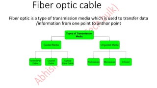
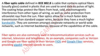
Fiber optic cable
Fiber optic is a type of transmission media which is used to transfer data
/information from one point to anthor point
A fiber optic cable defined in IEEE 802.8 is cable that contains optical fibers
(usually glass) coated in plastic that are used to send data by pulses of light.
The coating helps protect the fibers from heat, cold, electromagnetic
interference from other types of wiring, as well as some protection from
ultraviolet rays from the sun. Fiber optics allow for a much faster data
transmission than standard copper wires, because they have a much higher
bandwidth. They are common amongst corporate networks or world-wide
networks, such as Internet backbones, because of the capabilities of the cable.
Fiber optics are also commonly used in telecommunication services such as
internet, television and telephones. As an example, companies such as Verizon
and Google use fiber optics in their Verizon FIOS and Google Fiber services,
providing gigabit internet speeds to users.
All fiber optic cable types are comprised of a core that transmits light, generally either glass or
plastic, a cladding which reflects that light to prevent loss, and surrounded by sheathing meant
to protect the core and cladding from damage. The thickness of these layers can vary,
depending on where the cable will be placed and what kind of performance is needed.
Advantages of fiber optic
1. Greater Bandwidth
Copper cables were originally designed for voice transmission and have a limited bandwidth.
Fiber optic cables provide more bandwidth
2. Faster Speeds
Fiber optic cables have a core that carries light to transmit data. This allows fiber optic cables to
carry signals at speeds that are only about 31 percent slower than the speed of light—faster
than Cat5 or Cat6 copper cables. There is also less signal degradation with fiber cables.
3. Longer Distances
Fiber optic cables can carry signals much farther than the typical 328-foot limitation for copper
cables. For example, some 10 Gbps singlemode fiber cables can carry signals almost 25
miles/40km. The actual distance depends on the type of cable, the wavelength and the network.
Optical fiber is rising in both telecommunication and data communication due to its unsurpassed
advantages: faster speed with less attenuation, less impervious to electromagnetic interference
(EMI), smaller size and greater information carrying capacity.
Disadvantages of fiber optic
• Installation Challenges
• Splicing fiber optic cabling is not easy and if they are bent or manipulated in shape too
much they will break. They are highly susceptible to being cut or damaged during
installation or through construction activity.
• Fragility
• Fiber optic cable is made of glass, which is more fragile than electrical wires such as
copper cabling. Not only that, but glass can be damaged by chemicals such as hydrogen
gas that can affect transmission. Particular care has to be taken with laying undersea
fiber cabling because of its fragility.
• Attenuation and Dispersion
• With long distance transmission, light will attenuate and disperse, which means
additional components such as EDFA (Erbium-doped fiber amplifier – an optical
repeater device that is used to boost the intensity of optical signals being carried
through a fiber optic communications system) are required.
• Cost
• Cost to produce fiber cabling is higher than that of copper
Speed of light in fiber optic cable 299792 KM/s
The standard line is that fiber optic networks transfer data at the speed of
light. But in reality, light travels about 31 percent slower through fiber
optical cables than it does through a vacuum. But that's changing.
Researchers at University of Southampton in England have found a way to
build cables that work at 99.7 percent of the speed of light in a vacuum.
Types of fiber optic cable
. SMF (single mode fiber)
. MMF (multi mode fiber)
SMF - Single mode fiber has a smaller core diameter 9 microns (8.3 microns to be exact) and only
allows a single wavelength and pathway for light to travel, which greatly decreases light
reflections and lowers attenuation.
MMF - Multimode fiber allows a large number of modes for the light ray traveling
through it. The core diameter is generally (40um) and that of cladding is (70um). The
relative refractive index difference is also greater than single mode fiber. It is not suitable
for long-distance communication due to large dispersion and attenuation of the signal.
• On the basis of refractive index its two types
I. Step index optical fiber
II. Graded index optical fiber
Step index MMF -
STEP-INDEX MULTIMODE FIBER has a large core, up to 100 microns in diameter. As a
result, some of the light rays that make up the digital pulse may travel a direct route,
whereas others zigzag as they bounce off the cladding
Graded index MMF –
Graded index multimode cables have a core arranged in concentric circles, like the cross
section of a tree. As light enters, it is transmitted through the rings with the outer rings
travelling faster than transmissions in the central core. This type of cable can handle many
wavelengths of light at once, making it perfect for clear communication and data transfer
requiring up to 100Gb transfer rate, as you would find at a large data center.
Submarine cables
TYPES OF MMF
OM1 vs OM2 vs OM3 vs OM4 vs OM5
• Multimode fibers are able to transmit different distance ranges at various data rate
• Physical difference mainly lies in diameter, jacket color, optical source and bandwidth
MMF Category Fast Ethernet 1GbE 10GbE 40GbE 100GbE
OM1 2000m 275m 33m / /
OM2 2000m 550m 82m / /
OM3 2000m / 300m 100m 70m
OM4 2000m / 550m 150m 150m
OM5 / / 550m 150m 150m
MMF Cable Type Diameter Jacket Color Optical Source Bandwidth
OM1 62.5/125µm Orange LED 200MHz*km
OM2 50/125µm Orange LED 500MHz*km
OM3 50/125µm Aqua VSCEL 2000MHz*km
OM4 50/125µm Aqua VSCEL 4700MHz*km
OM5 50/125µm Lime Green VSCEL 28000MHz*km
• OM1 FIBER - OM1 fiber typically comes with an orange jacket and have a core size of 62.5 µm.
It can support 10 Gigabit Ethernet at lengths of up to 33 meters. It is most commonly used for
100 Megabit Ethernet applications. This type commonly uses a LED light source.
Color – Orange
Core Size – 62.5um
Data Rate – 1GB @ 850nm
Distance – Up to 300 meters
Applications – Short-Haul Networks, Local Area Networks (LANs) & Private Networks
62.5/125 Multimode Duplex Fiber Cable
• OM2 FIBER - OM2 fiber also comes with an orange jacket and uses a LED light source
but with a smaller core size of 50 µm. It supports up to 10 Gigabit Ethernet at lengths
up to 82 meters but is more commonly used for 1 Gigabit Ethernet applications.
Color – Orange
Core Size – 50um
Data Rate – 1GB @ 850nm
Distance – Up to 600 meters
Generally used for shorter distances • 2x Distance Capacity of OM1
Applications – Short-Haul Networks, Local Area Networks (LANs) & Private Networks
OM2 Fiber Optic Multimode Cable
• OM3 FIBER - OM3 fiber comes with an aqua color jacket. Like the OM2, its core size is
50 µm, but the cable is optimized for laser based equipment. OM3 supports 10 Gigabit
Ethernet at lengths up to 300 meters. Besides, OM3 is able to support 40 Gigabit and
100 Gigabit Ethernet up to 100 meters, however, 10 Gigabit Ethernet is most commonly
used.
• Color – Aqua
• Core Size – 50um
• Date Rate – 10GB @ 850nm
• Distance – Up to 300 meters
• Uses fewer modes of light, enabling increased speeds
• Able to run 40GB or 100GB up to 100 meters utilizing a MPO connector
• Applications – Larger Private Networks
• 10 Gigabit Laser Optimized Aqua OM3 Fiber Optic Cables
• OM4 FIBER - OM4 fiber is completely backwards compatible with OM3 fiber and
shares the same distinctive aqua jacket. OM4 was developed specifically for VSCEL laser
transmission and allows 10 Gig/s link distances of up to 550m compared to 300M with
OM3. And it’s able to run 40/100GB up to 150 meters utilizing a MPO connector.
• Color – Aqua
• Core Size – 50um
• Data Rate – 10GB @ 850nm
• Distance – Up to 550 meters
• Able to run 100GB up to 150 meters utilizing a MPO connector
• Applications – High-Speed Networks – Data Centers, Financial Centers & Corporate Campuses
• OM4 50µ - Multimode 10Giga/550m optimized Cables
• OM5 FIBER - OM5 fiber, also known as WBMMF (wideband multimode fiber), is the
newest type of multimode fiber, and it is backwards compatible with OM4. It has the
same core size as OM2, OM3, and OM4. The color of OM5 fiber jacket was chosen as
lime green. It is designed and specified to support at least four WDM channels at a
minimum speed of 28Gbps per channel through the 850-953 nm window. More details
can be found at: Three Critical Focuses on OM5 Fiber Optic Cable
OM5 may be a potential new option for data centers that require greater link distances
and higher speeds.
Single mode fiber types
• OS 1 (optical SMF)
• OS 2 (optical SMF)
• OS 1 - Is an old fiber specification that was introduced back in 2002, which mechanical,
environmental and optical features comply with ITU-T G.652A or ITU-T G.652B
standards. It is a tight buffered cable, suitable for indoor applications, such as data
centers or enterprises campuses.
• It has an attenuation of 1 dB per kilometer and a top transmission distance of 2 km at
10 Gigabit Ethernet. It works between 1310 nm and 1550 nm.
• OS 2 - It was introduced back in 2006 under the ITU-T G.652C and ITU-T G.652D specifications.
It is manufactured with a chemical process that reduces the presence of hydroxyl ions in order
to decrease loss at the water peak region.
It is a loose tube fiber recommended to be used in outdoor applications, even in underground
conditions. OS2 fiber has an attenuation of 0.4 dB between 1310 nm and 1550 nm, (Outdoor
Use) high fiber count, long distance telco backbone and backhaul lines, direct bury applications
along streets and railroads. OS2 can support speeds up to 100G and distances up to 200km (124
miles).
Name OS1 OS2
Standards ITU-T G.652A/B/C/D ITU-T G.652C/D
Construction Tight buffered Loose tube
Application Indoor Outdoor
Attenuation 1.0db/km 0.4db/km
Distance 2 km 200KM
Price Low High
Fiber patch cord connectors
• SC connector – The SC connector was developed in Japan by NTT (the Japanese
telecommunications company), and is believed to stand for ‘Subscriber Connector’ or
‘Standard Connector’.
• SC connectors use a round 2.5mm ferrule and come with a locking tab that enables
push on / pull off mating mechanism to offer quick insertion and removal. The SC
connector can be utilised with single-mode and multi-mode fibre optic cables.
• The connector body of an SC connector is square shaped. Two SC connectors are
commonly bound together with a plastic clip, creating a duplex connection.
LC connector -Developed by Lucent Technologies, the LC connector otherwise known as a
‘Lucent Connector’ measures about half the size of an SC connector.
• Available in simplex or duplex versions, LC connectors can be used with both single-mode and
multi-mode cables.
• The LC connector uses a 1.25mm ferrule with a retaining tab mechanism.
ST connector - connectors were one of the first connector types widely implemented in fibre
optic networking applications. Originally developed by AT&T, ST stands for ‘Straight Tip’
connector.
• The ST connector utilises a 2.5mm ferrule with a round plastic or metal body. The connector
stays in place with the help of a “twist-on/twist-off” bayonet-style lock mechanism.
• FC connector - FC is an acronym for ‘ferrule connector” or ‘fibre channel’.
• The connectors have a threaded body and a position locatable notch to achieve exact locating
of the SMF in relation to the receiver and the optical source. Once the connector is installed,
its position is maintained with total precision.
• The FC is designed for durable connections, and can be used in high-vibration environments.
MTP/MPO connector - MPO is a fiber connector type while MTP is a registered trademark of an MPO
connector manufactured by US Conec. All MTPs are MPOs but not all MPOs are MTPs.
• MPO stands for Multi-Fiber Push On. This connector is commonly used to terminate multi-fiber ribbon
connections in indoor environments. It conforms to IEC-61754-7; EIA/TIA-604-5 (FOCIS 5) standards.
MTP is a brand name for an MPO connector manufactured by US Conec. It conforms to MPO specs. MTP stands for
“Multi-fiber Termination Push-on” connector. MTP connectors are engineered for high mechanical and optical specs
MPO or MTP terminated cables are widely used in high density cabling environments like data centers. Traditional,
tight-buffered multi-fibre cable needs to have each fiber individually terminated by a skilled technician. MPO cable
which carries multiple fibers, comes pre-terminated. Factory terminated MPO / MTP connectors commonly have
either 12 fiber or 24 fiber array.
The MPO connector can be either male or female. You can tell the male connector
MTP/MPO cables accommodating more fibers in one multi-fiber MTP/MPO connector came into the market,
which prove to be practical solutions for 40G/100G/400G high-density cabling in data centers.
TYPES OF MTP/MPO CABLE –
MTP/MPO cables are classified into three types: trunk cable, harness cable and conversion cable.
Trunk cable - MTP/MPO trunk cable is a cable with two MPO or MTP connectors at both ends, with nothing
different from ordinary patch cables seen from outside. However, the truth is that the cable usually
accommodates 12, 24, 48 and even 72 fibers, and the ends are terminated with 12-fiber or 24-fiber MTP/MPO
connectors according to customer’s choice. FS MTP/MPO trunk cables are designed for high density application
which offers excellent benefits in terms on site installation time and space saving. They are available in multiple
lengths and in single mode, multimode OM1, OM2, OM3 or OM4 with LSZH or PVC Jackets. With BIF, FS MTP
and MPO cables are designed for improved bend performance in reduced-radius applications such as residential
or office environments which have less bend sensitivity.
MTP cascatette
MPO Breakout cable –
The MPO to LC breakout cable is also an economical solution for a smaller network environment
in which you don’t need complicated equipment, because the MPO cable allows redistribution
of various fibers into one round cable for short distance transmission, it offers 8, 12, 24 and up
to 144 fibers for these applications.
• OM3 & OM4 types MPO-LC breakout cable are very popular in markets. You might see both
aqua and magenta colors are used for OM4 cable, it’s just choice by different markets.
MPO/MTP breakout cable offers up to 144 fibers, but most common versions are 8, 12 and
24. 8F is usually with 4 LC duplex connectors, because they connect with SFP transceivers,
which normally have small LC duplex ports. Each pair of fibers for TX & RX of 10G.
MTP conversion cable –
MTP/MPO conversion cables have the same fanout design as MTP/MPO breakout cables but are
different in fiber counts and types. They are terminated with MTP/MPO connectors on both
ends. Specifically, commonly-used ones are 24-fiber to 2×12-fiber, 24-fiber to 3×8-fiber, 2×12-
fiber to 3×8-fiber MTP/MPO conversion cables. They are especially ideal for 10G-40G, 40G-
40G, 40G-100G, 40G-120G connections.
LC connector vs SC connector –
• Size: LC is half the size of SC. Actually, one SC-adapter is exactly the same size as a duplex LC-adapter. Therefore
LC is more and more common in central offices where packing density (number of connections per area) is an
important cost factor
• Handling: SC is a true “push-pull-connector” and LC is a “latched connector”, although there are very innovative,
real “push-pull-LCs” available which have the same handling capabilities like SC.
• The History of Connector: The LC is the “younger” connector of the two, SC is wider spread around the world but
LC is catching up. Both connectors have the same insertion loss and return loss capabilities. Generally, it depends
where in the network you want to use the connector, no matter SC or LC, even the other different
kinds of connect
Simplex/duplex LC VS SC fiber –
Single mode and multimode simplex optic patch cords can be used for applications that only require one-way
data transfer. They are usually used to accomplish connectivity between two BiDi transceivers, which is usually
designed with LC simplex single mode fiber to fit the optical interface of the BiDi SFP/ SFP+ optics and
operating wavelength. In addition, simplex BiDi WDM Mux/DeMux is designed for use in single strand fiber
transmission. So it also needs the simplex fiber cable to combine and separate wavelengths. In addition to
these equipments, there are so many other components associated with simplex fiber solution, such as
simplex PLC (Planar Lightwave Circuit) splitters, OADM (Optical Add Drop Multiplexer) and other simplex fiber
products. As for duplex fiber optic cables, they are usually used in standard optical transceivers, such as SFP,
10G SFP+, 40G QSFP+ and 100G QSFP 28 (only LC duplex fiber cables can be used for long distance, such as
40G-LR4 and 100G-LR4). When the distance between two device is too long, duplex fiber is also used for
interconnector or cross connector between fiber optic transceivers and MPO/MTP cassettes.
Fiber polish type –
• APC vs UPC vs FLAT vs PC
the main difference between UPC and APC connector is the fiber end face. UPC connectors are polished with no
angle, but APC connectors feature a fiber end face that is polished at an 8-degree angle. With UPC connectors,
any reflected light is reflected straight back towards the light source. However, the angled end face of the APC
connector causes reflected light to reflect at an angle into the cladding versus straight back toward the source.
This causes some differences in return loss. Therefore, UPC connector is usually required to have at least -50dB
return loss or higher, while APC connector return loss should be -60dB or higher. In general, the higher the return
loss the better the performance of the mating of two connectors. Besides the fiber end face, another more
obvious difference is the color. Generally, UPC connectors are blue while APC connectors are green.
Multimode fiber UPC connector are GREY
• Fiber Optic Cable Jacket Material
• Fiber cable jacket is made of various types of materials. It’s important to consider the jacket
type when selecting the compatibility with the application’s connectors and environment. The
table below contains some of the most common fiber cable jacket material types used both
indoor and outdoor cables:
Jacket Material Benefit of Jacket Material
PE (Polyethylene) PE has excellent properties of moisture and weather resistance, and
has the good electrical properties over a wide temperature range. It's also abrasion resistant.
So PE is the standard jacket material for outdoor fiber optic cables.
PVC (Polyvinyl Chloride ) PVC is usually low-cost, flexible, fairly rugged, and a flame/oil-
resistant material, so it can be formulated to function in a variety of environments and
applications. In other words, it can be used as the jacket materials for both indoor and
outdoor cables.
PVDF (Polyvinyl Difluoride) PVDF is used for plenum cables, because it has better fire-
retardant properties than PE and produces little smoke.
LSZH (Low Smoke Zero Halogen) LSZH jacket is free of halogenated materials which can be
transformed into toxic and corrosive matte during combustion. LSZH materials are used to
make a special cable called LSZH cable, which is a good choice for inner installations. But it is
the most expensive jacket material.
• Fiber Optic Cable Fire Rating
• Typically, there are eight levels of fire resistance for both non-conductive and conductive cables
specified by NEC (National Electrical Code). All indoor fiber optic cables must be marked and
installed properly for its intended use: plenums, risers and general purpose areas.
• Note:
• (1) A Plenum area is a building space used for air flow or air distribution system (drop ceiling and
raised floors).
• (2) A Riser area is a floor opening, shaft or duct that runs vertically through one or more floors.
• (3) A general purpose area is all other area that is not plenum or riser and on the same floor.
• OFNP vs. OFNR
• As mentioned above, OFNP and OFNR are two types of fiber optic cables that are used in buildings.
OFNP cables have fire-resistance and low smoke production characteristics. This is the highest fire
rating fiber cable and no other cable types can be used as substitutes. So these cables are mostly
installed in plenum areas. Whereas, the fiber-resistance and low smoke of OFNR cables are not good as
OFNP. OFNP plenum cables can be used as substitutes for OFNR cables. Through OFNR vs. OFNP, it is
worth noticing that OFNR fiber optic cable cannot be used in plenum areas to replace OFNP cables,
however, the latter can be used in the riser areas. Both OFNP and OFNR can be used in general
purpose areas.
OPNP - Optical Fiber Non-conductive Plenum Cable
OFNR - Optical Fiber Non-conductive Rise Cable
THANK YOU

Fiber optic cable and its types including patchcables and connector types

  • 1.
    Fiber optic cable Fiberoptic is a type of transmission media which is used to transfer data /information from one point to anthor point
  • 2.
    A fiber opticcable defined in IEEE 802.8 is cable that contains optical fibers (usually glass) coated in plastic that are used to send data by pulses of light. The coating helps protect the fibers from heat, cold, electromagnetic interference from other types of wiring, as well as some protection from ultraviolet rays from the sun. Fiber optics allow for a much faster data transmission than standard copper wires, because they have a much higher bandwidth. They are common amongst corporate networks or world-wide networks, such as Internet backbones, because of the capabilities of the cable. Fiber optics are also commonly used in telecommunication services such as internet, television and telephones. As an example, companies such as Verizon and Google use fiber optics in their Verizon FIOS and Google Fiber services, providing gigabit internet speeds to users.
  • 3.
    All fiber opticcable types are comprised of a core that transmits light, generally either glass or plastic, a cladding which reflects that light to prevent loss, and surrounded by sheathing meant to protect the core and cladding from damage. The thickness of these layers can vary, depending on where the cable will be placed and what kind of performance is needed.
  • 4.
    Advantages of fiberoptic 1. Greater Bandwidth Copper cables were originally designed for voice transmission and have a limited bandwidth. Fiber optic cables provide more bandwidth 2. Faster Speeds Fiber optic cables have a core that carries light to transmit data. This allows fiber optic cables to carry signals at speeds that are only about 31 percent slower than the speed of light—faster than Cat5 or Cat6 copper cables. There is also less signal degradation with fiber cables. 3. Longer Distances Fiber optic cables can carry signals much farther than the typical 328-foot limitation for copper cables. For example, some 10 Gbps singlemode fiber cables can carry signals almost 25 miles/40km. The actual distance depends on the type of cable, the wavelength and the network. Optical fiber is rising in both telecommunication and data communication due to its unsurpassed advantages: faster speed with less attenuation, less impervious to electromagnetic interference (EMI), smaller size and greater information carrying capacity.
  • 5.
    Disadvantages of fiberoptic • Installation Challenges • Splicing fiber optic cabling is not easy and if they are bent or manipulated in shape too much they will break. They are highly susceptible to being cut or damaged during installation or through construction activity. • Fragility • Fiber optic cable is made of glass, which is more fragile than electrical wires such as copper cabling. Not only that, but glass can be damaged by chemicals such as hydrogen gas that can affect transmission. Particular care has to be taken with laying undersea fiber cabling because of its fragility. • Attenuation and Dispersion • With long distance transmission, light will attenuate and disperse, which means additional components such as EDFA (Erbium-doped fiber amplifier – an optical repeater device that is used to boost the intensity of optical signals being carried through a fiber optic communications system) are required. • Cost • Cost to produce fiber cabling is higher than that of copper
  • 6.
    Speed of lightin fiber optic cable 299792 KM/s The standard line is that fiber optic networks transfer data at the speed of light. But in reality, light travels about 31 percent slower through fiber optical cables than it does through a vacuum. But that's changing. Researchers at University of Southampton in England have found a way to build cables that work at 99.7 percent of the speed of light in a vacuum.
  • 7.
    Types of fiberoptic cable . SMF (single mode fiber) . MMF (multi mode fiber) SMF - Single mode fiber has a smaller core diameter 9 microns (8.3 microns to be exact) and only allows a single wavelength and pathway for light to travel, which greatly decreases light reflections and lowers attenuation.
  • 9.
    MMF - Multimodefiber allows a large number of modes for the light ray traveling through it. The core diameter is generally (40um) and that of cladding is (70um). The relative refractive index difference is also greater than single mode fiber. It is not suitable for long-distance communication due to large dispersion and attenuation of the signal. • On the basis of refractive index its two types I. Step index optical fiber II. Graded index optical fiber
  • 10.
    Step index MMF- STEP-INDEX MULTIMODE FIBER has a large core, up to 100 microns in diameter. As a result, some of the light rays that make up the digital pulse may travel a direct route, whereas others zigzag as they bounce off the cladding
  • 11.
    Graded index MMF– Graded index multimode cables have a core arranged in concentric circles, like the cross section of a tree. As light enters, it is transmitted through the rings with the outer rings travelling faster than transmissions in the central core. This type of cable can handle many wavelengths of light at once, making it perfect for clear communication and data transfer requiring up to 100Gb transfer rate, as you would find at a large data center.
  • 13.
  • 14.
    TYPES OF MMF OM1vs OM2 vs OM3 vs OM4 vs OM5
  • 15.
    • Multimode fibersare able to transmit different distance ranges at various data rate • Physical difference mainly lies in diameter, jacket color, optical source and bandwidth MMF Category Fast Ethernet 1GbE 10GbE 40GbE 100GbE OM1 2000m 275m 33m / / OM2 2000m 550m 82m / / OM3 2000m / 300m 100m 70m OM4 2000m / 550m 150m 150m OM5 / / 550m 150m 150m MMF Cable Type Diameter Jacket Color Optical Source Bandwidth OM1 62.5/125µm Orange LED 200MHz*km OM2 50/125µm Orange LED 500MHz*km OM3 50/125µm Aqua VSCEL 2000MHz*km OM4 50/125µm Aqua VSCEL 4700MHz*km OM5 50/125µm Lime Green VSCEL 28000MHz*km
  • 16.
    • OM1 FIBER- OM1 fiber typically comes with an orange jacket and have a core size of 62.5 µm. It can support 10 Gigabit Ethernet at lengths of up to 33 meters. It is most commonly used for 100 Megabit Ethernet applications. This type commonly uses a LED light source. Color – Orange Core Size – 62.5um Data Rate – 1GB @ 850nm Distance – Up to 300 meters Applications – Short-Haul Networks, Local Area Networks (LANs) & Private Networks 62.5/125 Multimode Duplex Fiber Cable
  • 17.
    • OM2 FIBER- OM2 fiber also comes with an orange jacket and uses a LED light source but with a smaller core size of 50 µm. It supports up to 10 Gigabit Ethernet at lengths up to 82 meters but is more commonly used for 1 Gigabit Ethernet applications. Color – Orange Core Size – 50um Data Rate – 1GB @ 850nm Distance – Up to 600 meters Generally used for shorter distances • 2x Distance Capacity of OM1 Applications – Short-Haul Networks, Local Area Networks (LANs) & Private Networks OM2 Fiber Optic Multimode Cable
  • 18.
    • OM3 FIBER- OM3 fiber comes with an aqua color jacket. Like the OM2, its core size is 50 µm, but the cable is optimized for laser based equipment. OM3 supports 10 Gigabit Ethernet at lengths up to 300 meters. Besides, OM3 is able to support 40 Gigabit and 100 Gigabit Ethernet up to 100 meters, however, 10 Gigabit Ethernet is most commonly used. • Color – Aqua • Core Size – 50um • Date Rate – 10GB @ 850nm • Distance – Up to 300 meters • Uses fewer modes of light, enabling increased speeds • Able to run 40GB or 100GB up to 100 meters utilizing a MPO connector • Applications – Larger Private Networks • 10 Gigabit Laser Optimized Aqua OM3 Fiber Optic Cables
  • 19.
    • OM4 FIBER- OM4 fiber is completely backwards compatible with OM3 fiber and shares the same distinctive aqua jacket. OM4 was developed specifically for VSCEL laser transmission and allows 10 Gig/s link distances of up to 550m compared to 300M with OM3. And it’s able to run 40/100GB up to 150 meters utilizing a MPO connector. • Color – Aqua • Core Size – 50um • Data Rate – 10GB @ 850nm • Distance – Up to 550 meters • Able to run 100GB up to 150 meters utilizing a MPO connector • Applications – High-Speed Networks – Data Centers, Financial Centers & Corporate Campuses • OM4 50µ - Multimode 10Giga/550m optimized Cables
  • 20.
    • OM5 FIBER- OM5 fiber, also known as WBMMF (wideband multimode fiber), is the newest type of multimode fiber, and it is backwards compatible with OM4. It has the same core size as OM2, OM3, and OM4. The color of OM5 fiber jacket was chosen as lime green. It is designed and specified to support at least four WDM channels at a minimum speed of 28Gbps per channel through the 850-953 nm window. More details can be found at: Three Critical Focuses on OM5 Fiber Optic Cable OM5 may be a potential new option for data centers that require greater link distances and higher speeds.
  • 21.
    Single mode fibertypes • OS 1 (optical SMF) • OS 2 (optical SMF) • OS 1 - Is an old fiber specification that was introduced back in 2002, which mechanical, environmental and optical features comply with ITU-T G.652A or ITU-T G.652B standards. It is a tight buffered cable, suitable for indoor applications, such as data centers or enterprises campuses. • It has an attenuation of 1 dB per kilometer and a top transmission distance of 2 km at 10 Gigabit Ethernet. It works between 1310 nm and 1550 nm.
  • 22.
    • OS 2- It was introduced back in 2006 under the ITU-T G.652C and ITU-T G.652D specifications. It is manufactured with a chemical process that reduces the presence of hydroxyl ions in order to decrease loss at the water peak region. It is a loose tube fiber recommended to be used in outdoor applications, even in underground conditions. OS2 fiber has an attenuation of 0.4 dB between 1310 nm and 1550 nm, (Outdoor Use) high fiber count, long distance telco backbone and backhaul lines, direct bury applications along streets and railroads. OS2 can support speeds up to 100G and distances up to 200km (124 miles). Name OS1 OS2 Standards ITU-T G.652A/B/C/D ITU-T G.652C/D Construction Tight buffered Loose tube Application Indoor Outdoor Attenuation 1.0db/km 0.4db/km Distance 2 km 200KM Price Low High
  • 24.
    Fiber patch cordconnectors
  • 25.
    • SC connector– The SC connector was developed in Japan by NTT (the Japanese telecommunications company), and is believed to stand for ‘Subscriber Connector’ or ‘Standard Connector’. • SC connectors use a round 2.5mm ferrule and come with a locking tab that enables push on / pull off mating mechanism to offer quick insertion and removal. The SC connector can be utilised with single-mode and multi-mode fibre optic cables. • The connector body of an SC connector is square shaped. Two SC connectors are commonly bound together with a plastic clip, creating a duplex connection.
  • 26.
    LC connector -Developedby Lucent Technologies, the LC connector otherwise known as a ‘Lucent Connector’ measures about half the size of an SC connector. • Available in simplex or duplex versions, LC connectors can be used with both single-mode and multi-mode cables. • The LC connector uses a 1.25mm ferrule with a retaining tab mechanism. ST connector - connectors were one of the first connector types widely implemented in fibre optic networking applications. Originally developed by AT&T, ST stands for ‘Straight Tip’ connector. • The ST connector utilises a 2.5mm ferrule with a round plastic or metal body. The connector stays in place with the help of a “twist-on/twist-off” bayonet-style lock mechanism.
  • 27.
    • FC connector- FC is an acronym for ‘ferrule connector” or ‘fibre channel’. • The connectors have a threaded body and a position locatable notch to achieve exact locating of the SMF in relation to the receiver and the optical source. Once the connector is installed, its position is maintained with total precision. • The FC is designed for durable connections, and can be used in high-vibration environments.
  • 28.
    MTP/MPO connector -MPO is a fiber connector type while MTP is a registered trademark of an MPO connector manufactured by US Conec. All MTPs are MPOs but not all MPOs are MTPs. • MPO stands for Multi-Fiber Push On. This connector is commonly used to terminate multi-fiber ribbon connections in indoor environments. It conforms to IEC-61754-7; EIA/TIA-604-5 (FOCIS 5) standards. MTP is a brand name for an MPO connector manufactured by US Conec. It conforms to MPO specs. MTP stands for “Multi-fiber Termination Push-on” connector. MTP connectors are engineered for high mechanical and optical specs MPO or MTP terminated cables are widely used in high density cabling environments like data centers. Traditional, tight-buffered multi-fibre cable needs to have each fiber individually terminated by a skilled technician. MPO cable which carries multiple fibers, comes pre-terminated. Factory terminated MPO / MTP connectors commonly have either 12 fiber or 24 fiber array. The MPO connector can be either male or female. You can tell the male connector
  • 30.
    MTP/MPO cables accommodatingmore fibers in one multi-fiber MTP/MPO connector came into the market, which prove to be practical solutions for 40G/100G/400G high-density cabling in data centers. TYPES OF MTP/MPO CABLE – MTP/MPO cables are classified into three types: trunk cable, harness cable and conversion cable. Trunk cable - MTP/MPO trunk cable is a cable with two MPO or MTP connectors at both ends, with nothing different from ordinary patch cables seen from outside. However, the truth is that the cable usually accommodates 12, 24, 48 and even 72 fibers, and the ends are terminated with 12-fiber or 24-fiber MTP/MPO connectors according to customer’s choice. FS MTP/MPO trunk cables are designed for high density application which offers excellent benefits in terms on site installation time and space saving. They are available in multiple lengths and in single mode, multimode OM1, OM2, OM3 or OM4 with LSZH or PVC Jackets. With BIF, FS MTP and MPO cables are designed for improved bend performance in reduced-radius applications such as residential or office environments which have less bend sensitivity.
  • 31.
  • 32.
    MPO Breakout cable– The MPO to LC breakout cable is also an economical solution for a smaller network environment in which you don’t need complicated equipment, because the MPO cable allows redistribution of various fibers into one round cable for short distance transmission, it offers 8, 12, 24 and up to 144 fibers for these applications. • OM3 & OM4 types MPO-LC breakout cable are very popular in markets. You might see both aqua and magenta colors are used for OM4 cable, it’s just choice by different markets. MPO/MTP breakout cable offers up to 144 fibers, but most common versions are 8, 12 and 24. 8F is usually with 4 LC duplex connectors, because they connect with SFP transceivers, which normally have small LC duplex ports. Each pair of fibers for TX & RX of 10G.
  • 33.
    MTP conversion cable– MTP/MPO conversion cables have the same fanout design as MTP/MPO breakout cables but are different in fiber counts and types. They are terminated with MTP/MPO connectors on both ends. Specifically, commonly-used ones are 24-fiber to 2×12-fiber, 24-fiber to 3×8-fiber, 2×12- fiber to 3×8-fiber MTP/MPO conversion cables. They are especially ideal for 10G-40G, 40G- 40G, 40G-100G, 40G-120G connections.
  • 34.
    LC connector vsSC connector – • Size: LC is half the size of SC. Actually, one SC-adapter is exactly the same size as a duplex LC-adapter. Therefore LC is more and more common in central offices where packing density (number of connections per area) is an important cost factor • Handling: SC is a true “push-pull-connector” and LC is a “latched connector”, although there are very innovative, real “push-pull-LCs” available which have the same handling capabilities like SC. • The History of Connector: The LC is the “younger” connector of the two, SC is wider spread around the world but LC is catching up. Both connectors have the same insertion loss and return loss capabilities. Generally, it depends where in the network you want to use the connector, no matter SC or LC, even the other different kinds of connect
  • 35.
    Simplex/duplex LC VSSC fiber – Single mode and multimode simplex optic patch cords can be used for applications that only require one-way data transfer. They are usually used to accomplish connectivity between two BiDi transceivers, which is usually designed with LC simplex single mode fiber to fit the optical interface of the BiDi SFP/ SFP+ optics and operating wavelength. In addition, simplex BiDi WDM Mux/DeMux is designed for use in single strand fiber transmission. So it also needs the simplex fiber cable to combine and separate wavelengths. In addition to these equipments, there are so many other components associated with simplex fiber solution, such as simplex PLC (Planar Lightwave Circuit) splitters, OADM (Optical Add Drop Multiplexer) and other simplex fiber products. As for duplex fiber optic cables, they are usually used in standard optical transceivers, such as SFP, 10G SFP+, 40G QSFP+ and 100G QSFP 28 (only LC duplex fiber cables can be used for long distance, such as 40G-LR4 and 100G-LR4). When the distance between two device is too long, duplex fiber is also used for interconnector or cross connector between fiber optic transceivers and MPO/MTP cassettes.
  • 36.
    Fiber polish type– • APC vs UPC vs FLAT vs PC the main difference between UPC and APC connector is the fiber end face. UPC connectors are polished with no angle, but APC connectors feature a fiber end face that is polished at an 8-degree angle. With UPC connectors, any reflected light is reflected straight back towards the light source. However, the angled end face of the APC connector causes reflected light to reflect at an angle into the cladding versus straight back toward the source. This causes some differences in return loss. Therefore, UPC connector is usually required to have at least -50dB return loss or higher, while APC connector return loss should be -60dB or higher. In general, the higher the return loss the better the performance of the mating of two connectors. Besides the fiber end face, another more obvious difference is the color. Generally, UPC connectors are blue while APC connectors are green. Multimode fiber UPC connector are GREY
  • 38.
    • Fiber OpticCable Jacket Material • Fiber cable jacket is made of various types of materials. It’s important to consider the jacket type when selecting the compatibility with the application’s connectors and environment. The table below contains some of the most common fiber cable jacket material types used both indoor and outdoor cables: Jacket Material Benefit of Jacket Material PE (Polyethylene) PE has excellent properties of moisture and weather resistance, and has the good electrical properties over a wide temperature range. It's also abrasion resistant. So PE is the standard jacket material for outdoor fiber optic cables. PVC (Polyvinyl Chloride ) PVC is usually low-cost, flexible, fairly rugged, and a flame/oil- resistant material, so it can be formulated to function in a variety of environments and applications. In other words, it can be used as the jacket materials for both indoor and outdoor cables. PVDF (Polyvinyl Difluoride) PVDF is used for plenum cables, because it has better fire- retardant properties than PE and produces little smoke. LSZH (Low Smoke Zero Halogen) LSZH jacket is free of halogenated materials which can be transformed into toxic and corrosive matte during combustion. LSZH materials are used to make a special cable called LSZH cable, which is a good choice for inner installations. But it is the most expensive jacket material.
  • 39.
    • Fiber OpticCable Fire Rating • Typically, there are eight levels of fire resistance for both non-conductive and conductive cables specified by NEC (National Electrical Code). All indoor fiber optic cables must be marked and installed properly for its intended use: plenums, risers and general purpose areas. • Note: • (1) A Plenum area is a building space used for air flow or air distribution system (drop ceiling and raised floors). • (2) A Riser area is a floor opening, shaft or duct that runs vertically through one or more floors. • (3) A general purpose area is all other area that is not plenum or riser and on the same floor. • OFNP vs. OFNR • As mentioned above, OFNP and OFNR are two types of fiber optic cables that are used in buildings. OFNP cables have fire-resistance and low smoke production characteristics. This is the highest fire rating fiber cable and no other cable types can be used as substitutes. So these cables are mostly installed in plenum areas. Whereas, the fiber-resistance and low smoke of OFNR cables are not good as OFNP. OFNP plenum cables can be used as substitutes for OFNR cables. Through OFNR vs. OFNP, it is worth noticing that OFNR fiber optic cable cannot be used in plenum areas to replace OFNP cables, however, the latter can be used in the riser areas. Both OFNP and OFNR can be used in general purpose areas. OPNP - Optical Fiber Non-conductive Plenum Cable OFNR - Optical Fiber Non-conductive Rise Cable
  • 40.