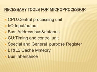
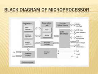
MICROPROCESSOR ORGANIZATION
R.PAVITHRA
I-MSc(it)
MICROPROCESSOR
 Micro processor is an electronic circuit that
functions as the central processing
unit(CPU)of a computer, providing
computational control.
 The microprocessor,(or CPU),is the brain of
the computer.
 A microprocessor is “a component that
implements memory”.
 Microprocessor is the core of the system.
MICRO PROCESSOR IMAGE
OPRATION TYPES IN MICROPROCCESSOR
 All of the operations of the microprocessor
can be classified into one of three types:
 Micro processor initiated operation
 Internal operations
 Peripheral initiated operations
MICROPROCESSOR ARCHITECTURE
 The microprocessor can be programmed to
perform functions on given data by writing
specific instruction into its memory.
 The microprocessor reads one instruction at a time
,matches it with its instruction set, and performs the
data manipulation specified.
 The result is either stored back into memory or
display on an output device.
NECESSARY TOOLS FOR MICROPROCESSOR
 CPU:Central processing unit
 I/O:Input/output
 Bus: Address bus&databus
 CU:Timing and control unit
 Special and General purpose Register
 L1&L2 Cache Mmeory
 Bus Inheritance
BLACK DIAGRAM OF MICROPROCESSOR
TIMING AND CONTROL UNIT
 CPU is partitioned into A.L.U&C.U.
 The function of control unit is to generate the
relevant timing&control singnals to all
operation in the computer.
 It controls the flow of the data between the
pricessor & memory &peripherals.
ARITHMETIC &LOGIC UNIT
 An arithmetic-logic
unit(ALU) is the part of a
CPU that carries out
arithmetic and logic
operations on the
operands in computer
instruction words.
 The ALU includes
storage places for input
operands, that are being
added, the accumulated
result(stored in an
accumulator), and
shifted results.
L1&L2 CACHE MEMORY
 L1 and L2 are levels of
cache memory in a
computer.
 “Level-1” cache memory
of cache memory,
usually bulit onto the
microprocessor chip
itself.
 L2 (that’s level-2) cache
memory is on a separate
chip(possibly on an
experience card) that
can be accessed more
quickly than the
larger”main”memory.
SPECIAL &GENERAL PURPOSE REGISTER
 General purpose register can be used as
either data or address register.
 There are 6 general purpose registers
namely B,C,D,E,H,L.
 Each of them is a 8-bit registers.
 They are used to hold data and results.
 To hold 16 bit data, combination of two 8-bits
registers can be used.
BUS INTERFACE
 The bus interface unit is the part of the
processor that interfaces with the rest of the PC.
 It deals with moving information over the
processor data bus, the primary conduit for the
transfer of information to and from the CPU.
 The bus interface unit is responsible for
responding to all signals that go to the
processor, and generating all signals that go
from the processor to other parts of the system.
DATA BUS
 A collection of wires in which data is
transmitted from one computer to another
external drive.
 The data bus carries digital information.
 The data bus is connected to the inputs of
several gates and to the outputs of several
gates.
ADDRESS BUS
 An address bus is a computer bus(a series of
lines connecting two or more devices) that is
used to specify a physical address.
 The width of the address bus determines the
amount of memory a system can address.
 It transfer the address of the location.
ADDRESS BUS MEMORY CAPACITY CHART
 Address bus size
20 bits
24 bits
32 bits
36 bits
40 bits
44bits
 Maximum RAM
1mb
16mb
4 gb
64gb
1tb
16tb
THANK YOU

Microprocessor organization in digital

  • 1.
  • 2.
    MICROPROCESSOR  Micro processoris an electronic circuit that functions as the central processing unit(CPU)of a computer, providing computational control.  The microprocessor,(or CPU),is the brain of the computer.  A microprocessor is “a component that implements memory”.  Microprocessor is the core of the system.
  • 3.
  • 4.
    OPRATION TYPES INMICROPROCCESSOR  All of the operations of the microprocessor can be classified into one of three types:  Micro processor initiated operation  Internal operations  Peripheral initiated operations
  • 5.
    MICROPROCESSOR ARCHITECTURE  Themicroprocessor can be programmed to perform functions on given data by writing specific instruction into its memory.  The microprocessor reads one instruction at a time ,matches it with its instruction set, and performs the data manipulation specified.  The result is either stored back into memory or display on an output device.
  • 6.
    NECESSARY TOOLS FORMICROPROCESSOR  CPU:Central processing unit  I/O:Input/output  Bus: Address bus&databus  CU:Timing and control unit  Special and General purpose Register  L1&L2 Cache Mmeory  Bus Inheritance
  • 7.
    BLACK DIAGRAM OFMICROPROCESSOR
  • 8.
    TIMING AND CONTROLUNIT  CPU is partitioned into A.L.U&C.U.  The function of control unit is to generate the relevant timing&control singnals to all operation in the computer.  It controls the flow of the data between the pricessor & memory &peripherals.
  • 9.
    ARITHMETIC &LOGIC UNIT An arithmetic-logic unit(ALU) is the part of a CPU that carries out arithmetic and logic operations on the operands in computer instruction words.  The ALU includes storage places for input operands, that are being added, the accumulated result(stored in an accumulator), and shifted results.
  • 10.
    L1&L2 CACHE MEMORY L1 and L2 are levels of cache memory in a computer.  “Level-1” cache memory of cache memory, usually bulit onto the microprocessor chip itself.  L2 (that’s level-2) cache memory is on a separate chip(possibly on an experience card) that can be accessed more quickly than the larger”main”memory.
  • 11.
    SPECIAL &GENERAL PURPOSEREGISTER  General purpose register can be used as either data or address register.  There are 6 general purpose registers namely B,C,D,E,H,L.  Each of them is a 8-bit registers.  They are used to hold data and results.  To hold 16 bit data, combination of two 8-bits registers can be used.
  • 12.
    BUS INTERFACE  Thebus interface unit is the part of the processor that interfaces with the rest of the PC.  It deals with moving information over the processor data bus, the primary conduit for the transfer of information to and from the CPU.  The bus interface unit is responsible for responding to all signals that go to the processor, and generating all signals that go from the processor to other parts of the system.
  • 13.
    DATA BUS  Acollection of wires in which data is transmitted from one computer to another external drive.  The data bus carries digital information.  The data bus is connected to the inputs of several gates and to the outputs of several gates.
  • 14.
    ADDRESS BUS  Anaddress bus is a computer bus(a series of lines connecting two or more devices) that is used to specify a physical address.  The width of the address bus determines the amount of memory a system can address.  It transfer the address of the location.
  • 15.
    ADDRESS BUS MEMORYCAPACITY CHART  Address bus size 20 bits 24 bits 32 bits 36 bits 40 bits 44bits  Maximum RAM 1mb 16mb 4 gb 64gb 1tb 16tb
  • 16.