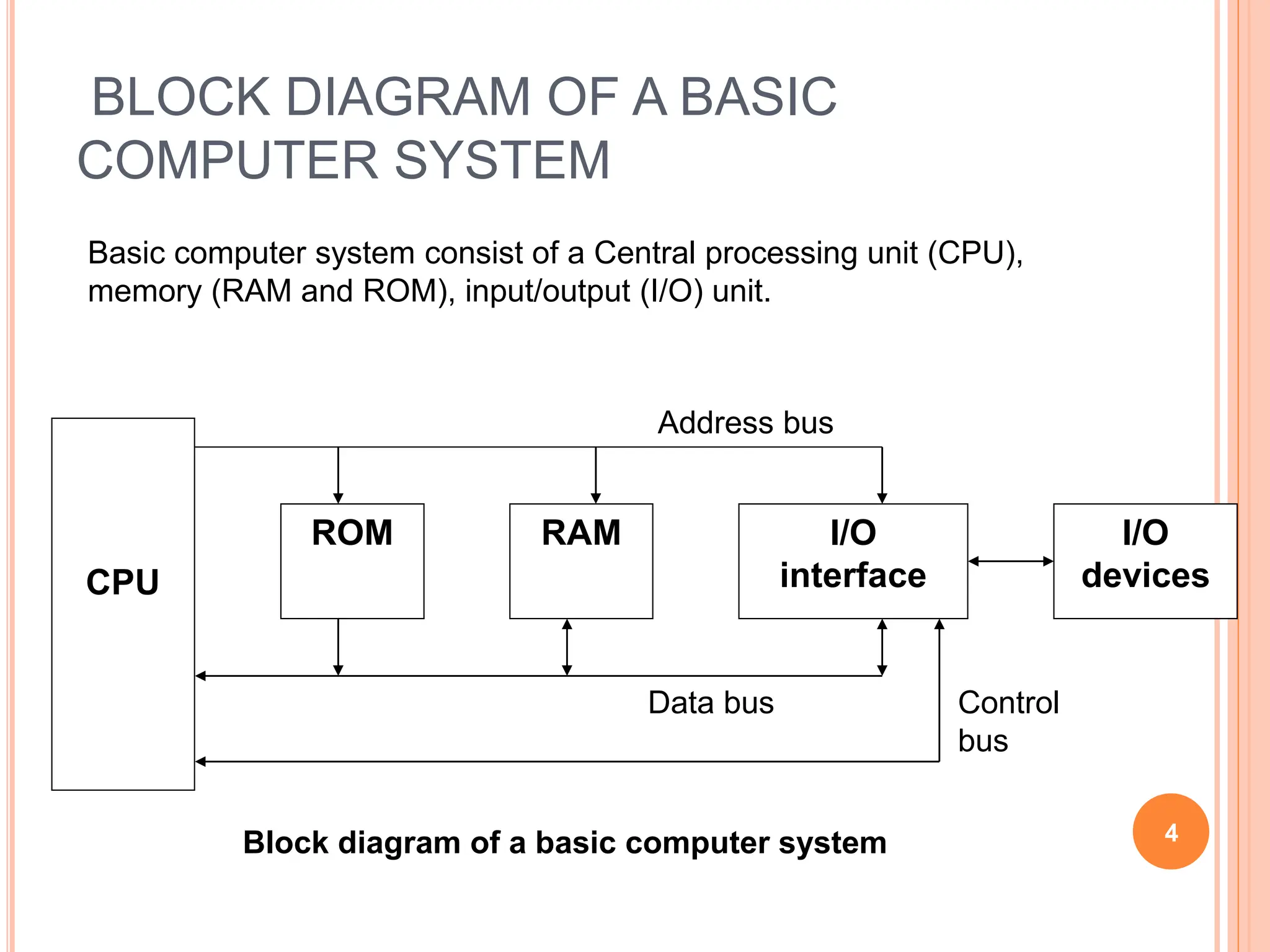
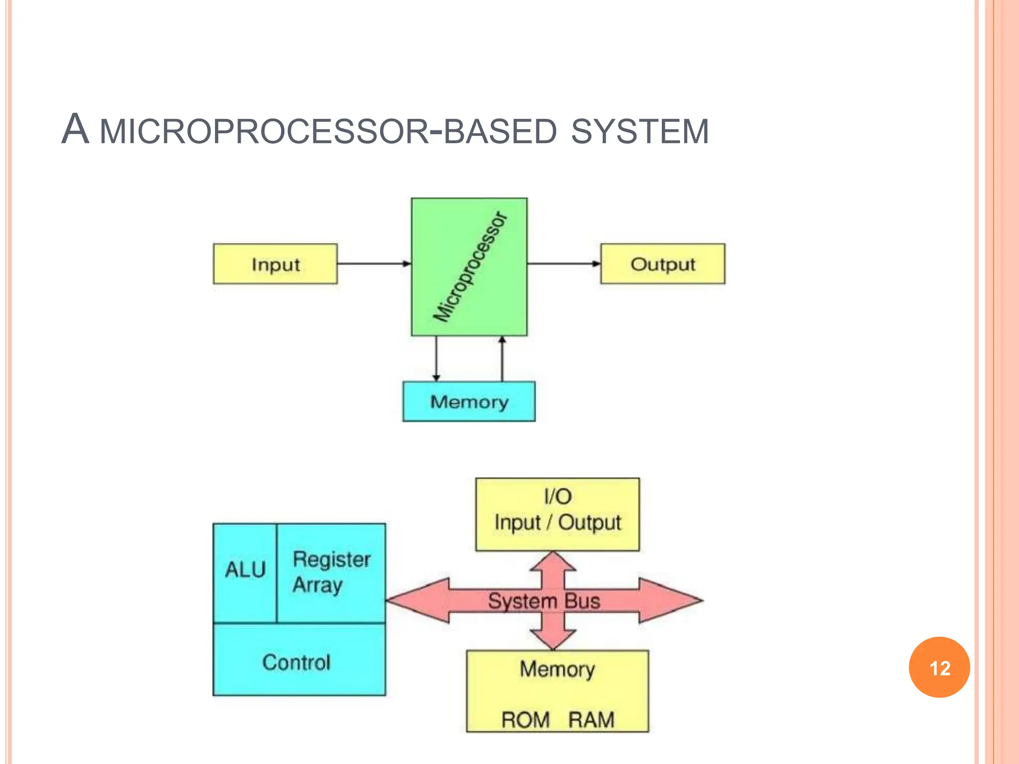
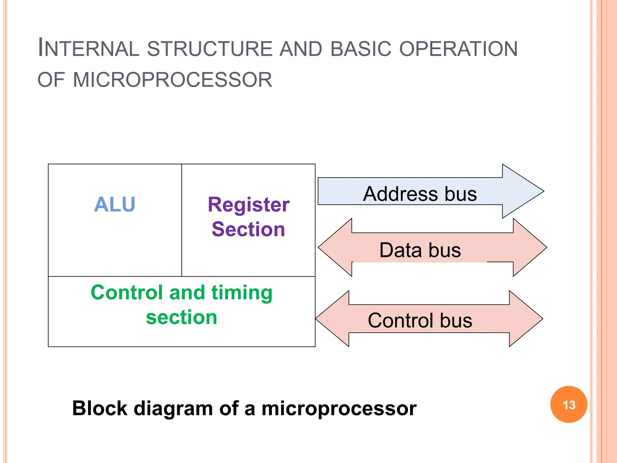
2. CHAPTER OUTLINE
Block diagram of a computer system
Basic components of a computer system using block
diagrams:
Cpu
Memory
Input and output unit
Evolution of microprocessor : 4,8,16,32 dan 64 byte
Nibble, byte, word dan longword
Fecthing and execution cycles.
Internal structure and basic operation of a microprocessor
(arithmetic and logic unit, control unit, register sets,
accumulator, condition code register, program counter, stack
pointer)
Bus system: data bus, address bus and control bus.
Microprocessor clock system
Examples of microprocessor: 8085,8086. 2
3. DIAGRAM OF A COMPUTER SYSTEM
A computer is a programmable machine that receives input, stores and
manipulates data//information, and provides output in a useful format.
3
Diagram Of A Computer System
4. BLOCK DIAGRAM OF A BASIC
COMPUTER SYSTEM
ROM RAM I/O
interface
I/O
devices
CPU
4
Basic computer system consist of a Central processing unit (CPU),
memory (RAM and ROM), input/output (I/O) unit.
Block diagram of a basic computer system
Address bus
Data bus Control
bus
5. BASIC COMPONENT OF MICROCOMPUTER
1. CPU - Central Processing Unit
the portion of a computer system that carries out the
instructions of a computer program
the primary element carrying out the computer's functions. It is
the unit that reads and executes program instructions.
The data in the instruction tells the processor what to do.
5
Pentium D dual core processors
6. 2. Memory
physical devices used to store data or programs.
Computer main memory comes in two principal varieties:
random-access memory (RAM) and read-only memory (ROM).
RAM can be read and written to anytime the CPU commands it,
but ROM is pre-loaded with data and software that never
changes, so the CPU can only read from it.
ROM is typically used to store the computer's initial start-up
instructions.
In general, the contents of RAM are erased when the power to
the computer is turned off, but ROM retains its data indefinitely.
In a PC, the ROM contains a specialized program called the
BIOS that orchestrates loading the computer's operating system
from the hard disk drive into RAM whenever the computer is
turned on or reset.
6
7. 3. I/O Unit
Input/output (I/O), refers to the communication between an
information processing system (such as a computer), and the
outside world possibly a human, or another information
processing system.
Inputs are the signals or data received by the system, and
outputs are the signals or data sent from it
Devices that provide input or output to the computer are called
peripherals
On a typical personal computer, peripherals include input devices
like the keyboard and mouse, and output devices such as the
display and printer. Hard disk drives, floppy disk drives and
optical disc drives serve as both input and output devices.
Computer networking is another form of I/O.
7
9. WHAT IS MICROPROCESSOR
The word comes from the combination micro and processor.
Processor means a device that processes whatever. In this context
processor means a device that processes numbers, specifically binary
numbers, o's and I’s.
To process means to manipulate.
It means to perform certain operations on numbers that depends on microprocessor
designs.
Definition of Microprocessor: The microprocessor is a programmable
device that takes in numbers, performs on them arithmetic or logical
operations according to the proqram stored in memory and then
produces other numbers as a result.
9
10. DEFINITION (CONTD)
Arithmetic and Logic Operations: Every
microprocessor has arithmetic operations such as
add and subtract as part of its instruction set. Most
microprocessors will have operations such as
multiply and divide.
In addition, microprocessors have logic operations as well. Such as AND,
OR, XOR, shift left, shift right, etc.
Again, the number and types of operations define
the microprocessor's instruction set and depends on the
specific microprocessor.
10
11. DEFINITION (CONTD)
Program: A program is a sequence of instructions that bring data into
the microprocessor, processes it and sends it out.
There are many programming languages (C, C++, FORTRAN, and JAVA...)
However, these programming languages can be grouped into three main levels
(these days a fourth level is developing).
Programming Languages:
Machine Language:
Assembly Language
High level language
11
13. INTERNAL STRUCTURE AND BASIC OPERATION
OF MICROPROCESSOR
ALU Register
Section
Control and timing
section
Address bus
Data bus
Control bus
13
Block diagram of a microprocessor
14. ARITHMETIC AND LOGIC UNIT (ALU)
The component that performs the arithmetic and
logical operations
the most important components in a microprocessor,
and is typically the part of the processor that is
designed first.
able to perform the basic logical operations (AND,
OR), including the addition operation.
14
16. CONTROL UNIT
The circuitry that controls the flow of information
through the processor, and coordinates the
activities of the other units within it.
In a way, it is the "brain within the brain", as it
controls what happens inside the processor, which
in turn controls the rest of the PC.
On a regular processor, the control unit performs
the tasks of fetching, decoding, managing
execution and then storing results.
16
17. REGISTER SETS
The register section/array consists completely of
circuitry used to temporarily store data or program
codes until they are sent to the ALU or to the
control section or to memory.
The number of registers are different for any
particular CPU and the more register a CPU have
will result in easier programming tasks.
Registers are normally measured by the number of
bits they can hold, for example, an "8-bit register" or
a "32-bit register". 17
18. REGISTER IN MOTOROLA 68000
MICROPROCESSOR
SUPERVISOR STACK POINTER
USER STACK POINTER
USER VYTE
SYSTEM BYTE
D0
D1
D2
D3
D4
D5
D6
D7
A0
A1
A2
A3
A4
A5
A6
A7
A7
PC
SR
31 16 15 8 7 0
31 16 15 8 7 0
15 8 7 0
DATA REGISTERS
ADDRESS REGISTERS
STACK POINTER
PROGRAM CONTER
STATUS REGISTER
18
19. ACCUMULATOR
a register in which intermediate arithmetic and logic
results are stored.
example for accumulator use is summing a list of
numbers.
The accumulator is initially set to zero, then each
number in turn is added to the value in the accumulator.
Only when all numbers have been added is the result
held in the accumulator written to main memory or to
another, non-accumulator, CPU register.
19
20. CONDITION CODE REGISTER (CCR) = FLAGS
an 8 bit register used to store the status of CPU,
such as carry, zero, overflow and half carry.
20
21. Flag Name Description
Z Zero flag Indicates that the result of a mathematical or logical operation was zero.
C Carry flag
Indicates that the result of an operation produced an answer greater
than the number of available bits. (This flag may also be set before a
mathematical operation as an extra operand to certain instructions, e.g.
"add with carry".)
X Extend flag
Masks the XIRQ request when set. It is set by the hardware and
cleared by the software as well is set by unmaskable XIRQ.
N Negative/ Sign flag
Indicates that the result of a mathematical operation is negative. In
some processors, the N and S flags have different meanings: the S flag
indicates whether a subtraction or addition has taken place, whereas
the N flag indicates whether the last operation result is positive or
negative.
V Overflow Flag
Indicates that the result of an operation has overflowed according to the
CPU's word representation, similar to the carry flag but for signed
operations.
I interrupts
Interrupts can be enabled or disabled by respectively setting or clearing
this flag. Modifying this flag may be restricted to programs executing in
supervisor mode
21
22. PROGRAM COUNTER (PC)
a 16 bit register, used to store the next
address of the operation code to be fetched
by the CPU.
Not much use in programming, but as an
indicator to user only.
Purpose of PC in a Microprocessor
to store address of tos (top of stack)
to store address of next instruction to be
executed.
count the number of instructions.
22
23. STACK POINTER (SP)
The stack is configured as a data structure
that grows downward from high memory to
low memory.
At any given time, the SP holds the 16-bit
address of the next free location in the
stack.
The stack acts like any other stack when
there is a subroutine call or on an interrupt.
ie. pushing the return address on a jump,
and retrieving it after the operation is
complete to come back to its original
location.
23
24. DATA BUS
The data bus is 'bi-directional'
data or instruction codes from memory or
input/output.are transferred into the
microprocessor
the result of an operation or computation is sent
out from the microprocessor to the memory or
input/output.
Depending on the particular microprocessor,
the data bus can handle 8 bit or 16 bit data.
24
25. ADDRESS BUS
The address bus is 'unidirectional', over which the
microprocessor sends an address code to the
memory or input/output.
The size (width) of the address bus is specified by
the number of bits it can handle.
The more bits there are in the address bus, the
more memory locations a microprocessor can
access.
A 16 bit address bus is capable of addressing
65,536 (64K) addresses.
25
26. CONTROL BUS
The control bus is used by the microprocessor to
send out or receive timing and control signals in
order to coordinate and regulate its operation and
to communicate with other devices, i.e. memory or
input/output.
26
27. MICRO PROCESSOR CLOCK
Also called clock rate, the speed at
which a microprocessor executes
instructions. Every computer contains
an internal clock that regulates the rate
at which instructions are executed and
synchronizes all the various computer
components.
27