i. The 8086 microprocessor is a 16-bit processor with 16-bit data bus and 20-bit address bus, allowing it to access up to 1 MB of memory space.
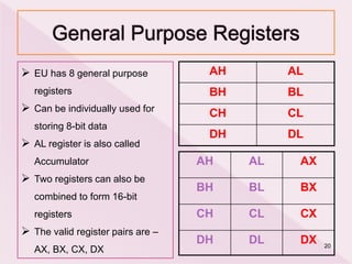
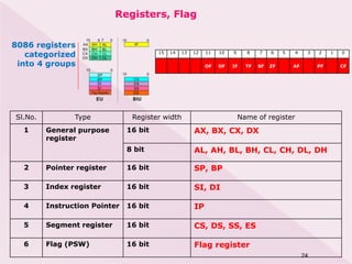
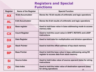
ii. It has 14 internal 16-bit registers used for storing data and addressing memory, including the Accumulator (AX), Base (BX), Count (CX), and Data (DX) registers.
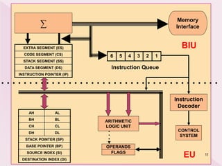
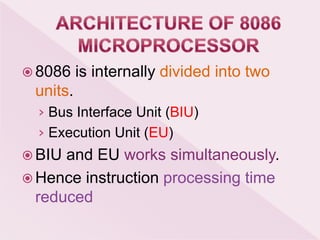
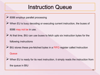
iii. The 8086 uses a Harvard architecture with separate buses for instructions and data, allowing it to fetch instructions simultaneously with data processing for improved performance.