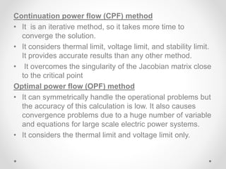
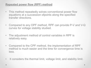
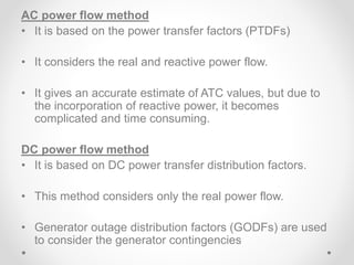
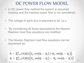
AVAILABLE
TRANSFER CAPABILITY(ATC) ON
OASIS
Presented by
Shridhar kulkarni
M-tech (power system)
(RIT Islampur)
1529010
Available transfer capability
• According to NERC definitions, ATC is nothing but the
remaining energy in the physical transmission network
for future commercial activity over and above already
committed uses.
• Mathematically,
ATC = TTC – TRM –CBM – ETC
• What is in the present deregulated scenario?
Various methods to calculate the
value of ATC are
1) Continuation power flow method (CPF)
2) Optimal power flow method (OPF)
3) Repeated power flow method (RPF)
ATC calculation based on sensitivity factors, using AC
power flow method and DC power flow method
Continuation power flow (CPF) method
• It is an iterative method, so it takes more time to
converge the solution.
• It considers thermal limit, voltage limit, and stability limit.
It provides accurate results than any other method.
• It overcomes the singularity of the Jacobian matrix close
to the critical point
Optimal power flow (OPF) method
• It can symmetrically handle the operational problems but
the accuracy of this calculation is low. It also causes
convergence problems due to a huge number of variable
and equations for large scale electric power systems.
• It considers the thermal limit and voltage limit only.
Repeated power flow (RPF) method
• This method repeatedly solves conventional power flow
equations at a succession ofpoints along the specified
transfer directions.
• Compared to any OPF method, RPF can provide P-V and V-Q
curves for voltage stability studied.
• The adjustment method of control variables in RPF is
relatively easy.
• Compared to the CPF method, the implementation of RPF
method is much easier and the time for convergence time is
less.
• It considers the thermal limit, voltage limit, and stability limit.
AC power flow method
• It is based on the power transfer factors (PTDFs)
• It considers the real and reactive power flow.
• It gives an accurate estimate of ATC values, but due to
the incorporation of reactive power, it becomes
complicated and time consuming.
DC power flow method
• It is based on DC power transfer distribution factors.
• This method considers only the real power flow.
• Generator outage distribution factors (GODFs) are used
to consider the generator contingencies
DC POWER FLOW MODEL
• In DC power flow method the system is assumed
lossless and the reactive power flow is not considered.
• The voltage of each bus is assumed to be 1p.u.
• By considering all these assumptions the Newton
Raphson load flow equations are modified.
• The Newton Raphson load flow equations can be
expressed as:
The resistance of transmission circuits is significantly less
than the reactance. Usually, it is the case that the x/r ratio is
between 2 and 10
If r is very small compared to x, then we observe that g will
be very small compared to b, and it is reasonable to
approximate equation (5) as:
𝑔 = 0 &𝑏 = − 1/ 𝑥
Now if 𝑔 = 0 then the real part of the elements of Y-bus
matrix will also be zero
Sine of the angle is angle itself. So, the load flow equations
become:
The voltages of each bus are assumed to be unity. So, the
load flow equations can be written as:
The reactive power flow in the lines is very small as
compared to the real power flow, so the reactive power flow
is not considered in DC power flow method.
THANK YOU

Atc calculation methods by shridhar kulkarni

  • 1.
    AVAILABLE TRANSFER CAPABILITY(ATC) ON OASIS Presentedby Shridhar kulkarni M-tech (power system) (RIT Islampur) 1529010
  • 2.
    Available transfer capability •According to NERC definitions, ATC is nothing but the remaining energy in the physical transmission network for future commercial activity over and above already committed uses. • Mathematically, ATC = TTC – TRM –CBM – ETC • What is in the present deregulated scenario?
  • 3.
    Various methods tocalculate the value of ATC are 1) Continuation power flow method (CPF) 2) Optimal power flow method (OPF) 3) Repeated power flow method (RPF) ATC calculation based on sensitivity factors, using AC power flow method and DC power flow method
  • 4.
    Continuation power flow(CPF) method • It is an iterative method, so it takes more time to converge the solution. • It considers thermal limit, voltage limit, and stability limit. It provides accurate results than any other method. • It overcomes the singularity of the Jacobian matrix close to the critical point Optimal power flow (OPF) method • It can symmetrically handle the operational problems but the accuracy of this calculation is low. It also causes convergence problems due to a huge number of variable and equations for large scale electric power systems. • It considers the thermal limit and voltage limit only.
  • 5.
    Repeated power flow(RPF) method • This method repeatedly solves conventional power flow equations at a succession ofpoints along the specified transfer directions. • Compared to any OPF method, RPF can provide P-V and V-Q curves for voltage stability studied. • The adjustment method of control variables in RPF is relatively easy. • Compared to the CPF method, the implementation of RPF method is much easier and the time for convergence time is less. • It considers the thermal limit, voltage limit, and stability limit.
  • 6.
    AC power flowmethod • It is based on the power transfer factors (PTDFs) • It considers the real and reactive power flow. • It gives an accurate estimate of ATC values, but due to the incorporation of reactive power, it becomes complicated and time consuming. DC power flow method • It is based on DC power transfer distribution factors. • This method considers only the real power flow. • Generator outage distribution factors (GODFs) are used to consider the generator contingencies
  • 7.
    DC POWER FLOWMODEL • In DC power flow method the system is assumed lossless and the reactive power flow is not considered. • The voltage of each bus is assumed to be 1p.u. • By considering all these assumptions the Newton Raphson load flow equations are modified. • The Newton Raphson load flow equations can be expressed as:
  • 8.
    The resistance oftransmission circuits is significantly less than the reactance. Usually, it is the case that the x/r ratio is between 2 and 10 If r is very small compared to x, then we observe that g will be very small compared to b, and it is reasonable to approximate equation (5) as: 𝑔 = 0 &𝑏 = − 1/ 𝑥 Now if 𝑔 = 0 then the real part of the elements of Y-bus matrix will also be zero
  • 9.
    Sine of theangle is angle itself. So, the load flow equations become: The voltages of each bus are assumed to be unity. So, the load flow equations can be written as: The reactive power flow in the lines is very small as compared to the real power flow, so the reactive power flow is not considered in DC power flow method.
  • 10.