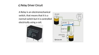
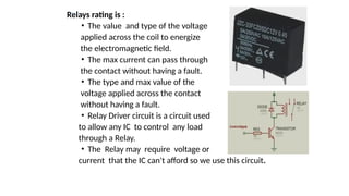
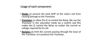
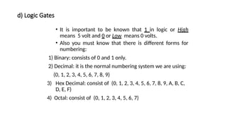
The document provides an in-depth overview of microcontrollers, detailing their components, functionalities, and applications. It explains critical concepts such as the differences between microcontrollers and microprocessors, various memory types, and the significance of input/output ports and communication protocols. Additionally, it elaborates on practical electronics elements like relays, logic gates, and interfacing techniques essential for effective microcontroller use.

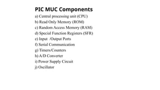
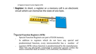

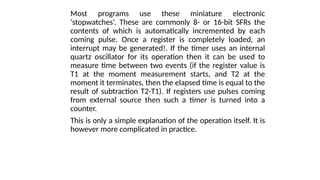
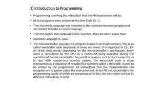
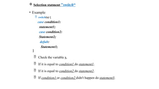
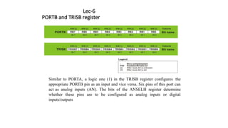
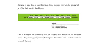
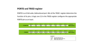
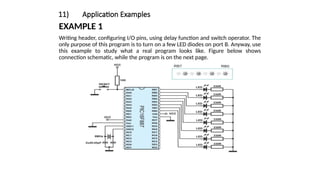
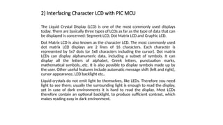
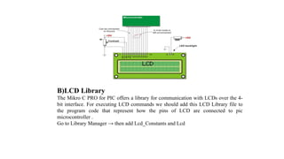
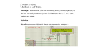
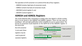
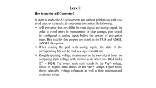
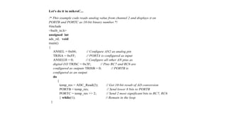
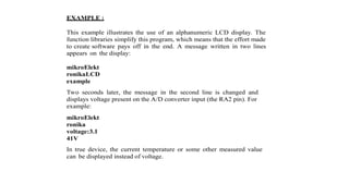
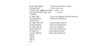
![• One of the most important things concerning serial communication
is the Protocol which should be strictly observed. It is a set of rules
which must be applied in order that devices can correctly interpret
data they mutually exchange. Fortunately, the microcontroller
automatically takes care of this, so that the work of the
programmer/user is reduced to simple write (data to be sent) and
read (received data).
• Baud Rate: The term baud rate is used to denote the number of bits
transferred per second [bps]. Note that it refers to bits, not bytes. It is
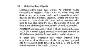
usually required by the protocol that each byte is transferred along
with several control bits. It means that one byte in serial data stream
may consist of 11 bits. For example, if the baud rate is 300 bps then
maximum 37 and minimum 27 bytes may be transferred per second.
• The most commonly used serial communication systems are:](https://image.slidesharecdn.com/controller-250114224531-9a439739/85/Micro-Controllers-engineering-computer-engineering-26-320.jpg)
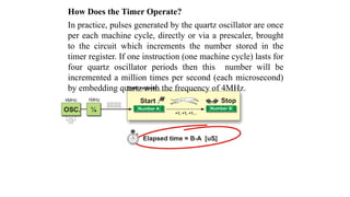
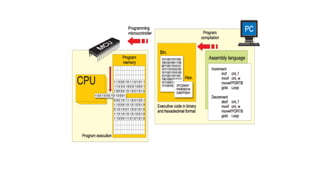
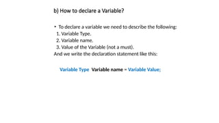
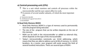
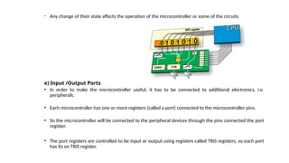
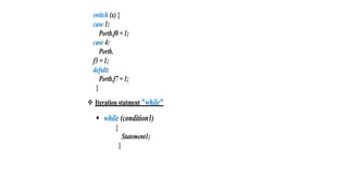
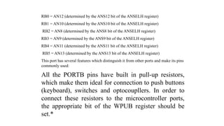
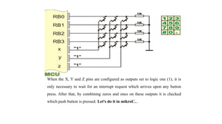
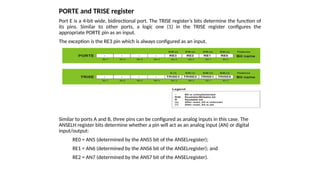
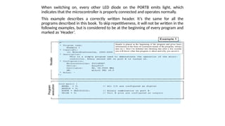
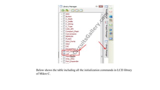
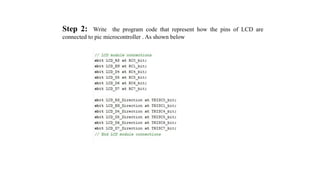
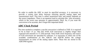
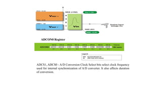
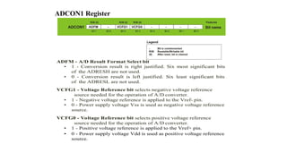
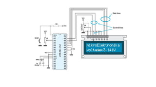
![d) Variable Name
• Variable Names must be Unique.
• Variable Names must begin with alphabetical characters (uppercase or
lowercase) or Underscore characters.
• It may contain numbers and can contain uppercase or lowercase
characters.
• Variable Names must not be like the reserved names of the compiler.
• It must not contain any special characters like ( ) : ; _ " ' & % $ # } [ { ].
• Examples:
• Correct Variable Names: (sum, Result, student_1, Student4, _sum).
• Wrong Variable Names: (5student, 5_student, #sum, if, switch, while, enum, case, else, asm, goto .....
e) Examples of Variable Declaration
• int x ;
• char n = 'A' ;
• float sum = 0 ;
• long z =12 ;
• Int L = 0b110011 ;](https://image.slidesharecdn.com/controller-250114224531-9a439739/85/Micro-Controllers-engineering-computer-engineering-57-320.jpg)

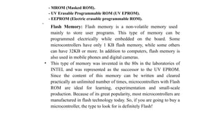
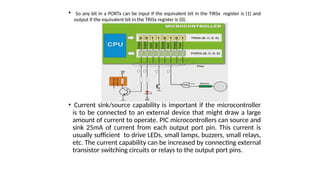
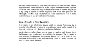
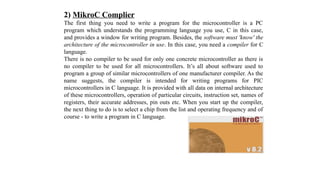
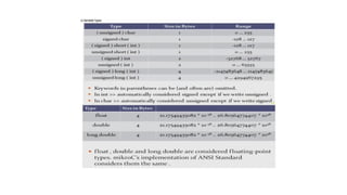
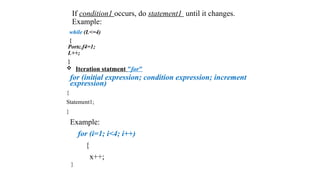
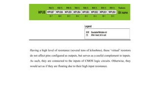
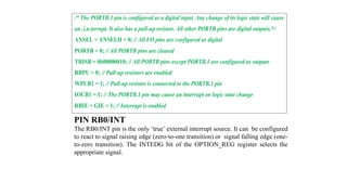
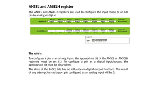
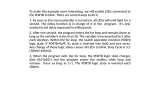
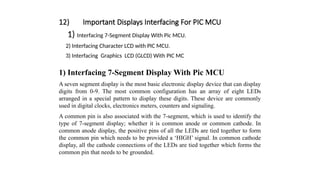
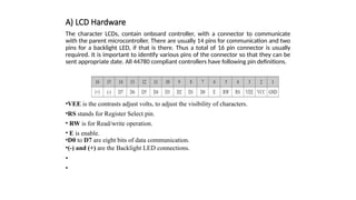
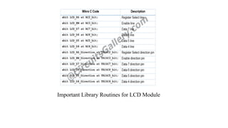
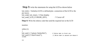
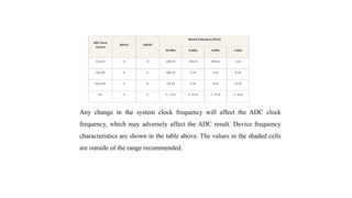
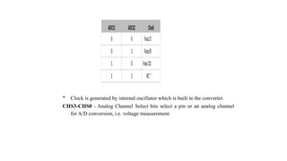
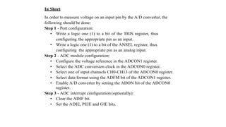
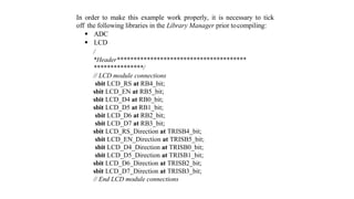
![a) What are Arrays and why using them?
•Array used to store elements with the same type in memory.
•We may use arrays to one operation to more than a couple of variables like adding
three number to an other three numbers in the same time.
•Arrays will help you to store and handle data easily during the program such as in
loops and many other uses.
b) How to declare an array?
Like a variable with declaring name and type but we need to
add the number of elements (optional).
Index of the elements of an array begins from zero.
char name [ ] = "Ahmed" ;
int numbers [4] = {1, 2, 3, 4} ;
char name [ ] = {'A', 'h', 'm', 'e', 'd'} ;](https://image.slidesharecdn.com/controller-250114224531-9a439739/85/Micro-Controllers-engineering-computer-engineering-59-320.jpg)

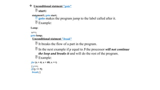

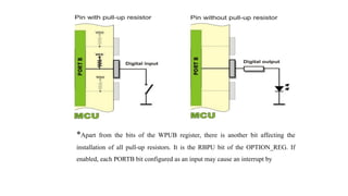
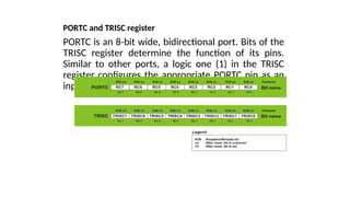
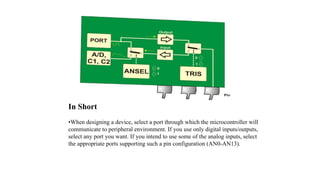

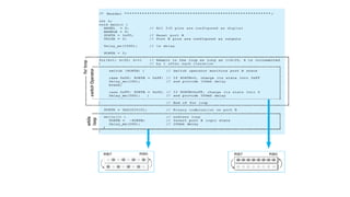
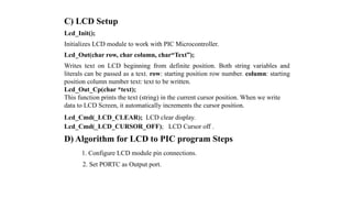
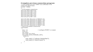
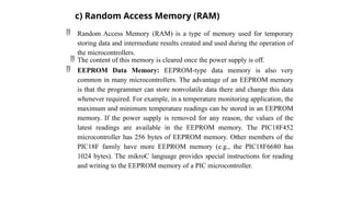
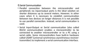
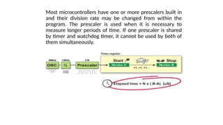
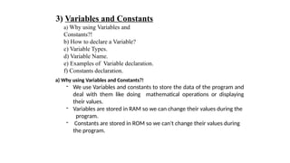
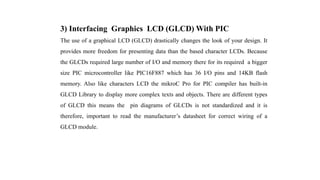
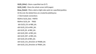
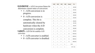
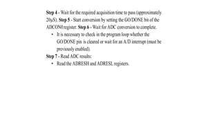
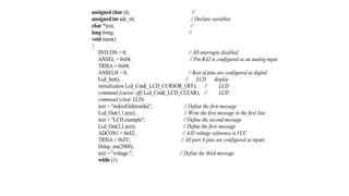
![// LCD module
connections sbit
LCD_RS at RB4_bit;
sbit LCD_EN at
RB5_bit; sbit
LCD_D4 at RB0_bit;
sbit LCD_D5 at
RB1_bit; sbit
LCD_D6 at RB2_bit;
sbit LCD_D7 at
RB3_bit;
sbit LCD_RS_Direction at
TRISB4_bit; sbit
LCD_EN_Direction at
TRISB5_bit; sbit
LCD_D4_Direction at
TRISB0_bit; sbit
LCD_D5_Direction at
TRISB1_bit; sbit
LCD_D6_Direction at
TRISB2_bit; sbit
LCD_D7_Direction at
TRISB3_bit;
// End LCD module connections
char txt1[] =
"mikroElektronika"; char
txt2[] = "EasyPIC6";
char txt3[] =
"Lcd4bit"; char
txt4[] =
"example";
char i; // Loop variable
void Move_Delay() { // Function used for text moving
Delay_ms(500); // You can change the moving speed here
}](https://image.slidesharecdn.com/controller-250114224531-9a439739/85/Micro-Controllers-engineering-computer-engineering-114-320.jpg)


![[Deck] What's New in Spark-Iceberg Integration via DSV2.pptx](https://cdn.slidesharecdn.com/ss_thumbnails/deckwhatsnewinspark-icebergintegrationviadsv2-260210005337-25955b12-thumbnail.jpg?width=640&height=640&fit=bounds)


