Download to read offline


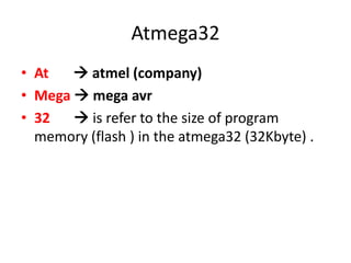

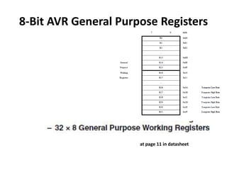

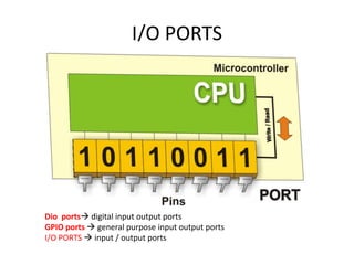
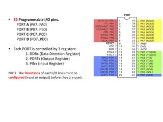
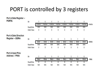
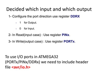
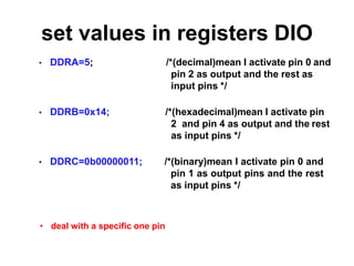
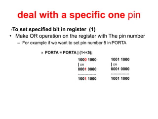


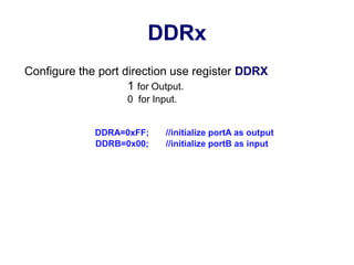

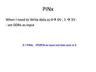

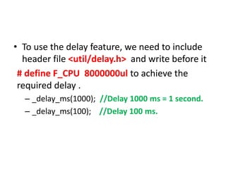

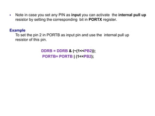

The document discusses the Atmega32 microcontroller. It has 32 KB of program memory and 32 programmable I/O pins across four ports (PORTA-PORTD). Each port is controlled by data direction, output, and input registers (DDRx, PORTx, PINx). The document explains how to configure the registers to set pin directions and write/read pin values. It also covers delays, buttons, and using internal pull-up resistors.