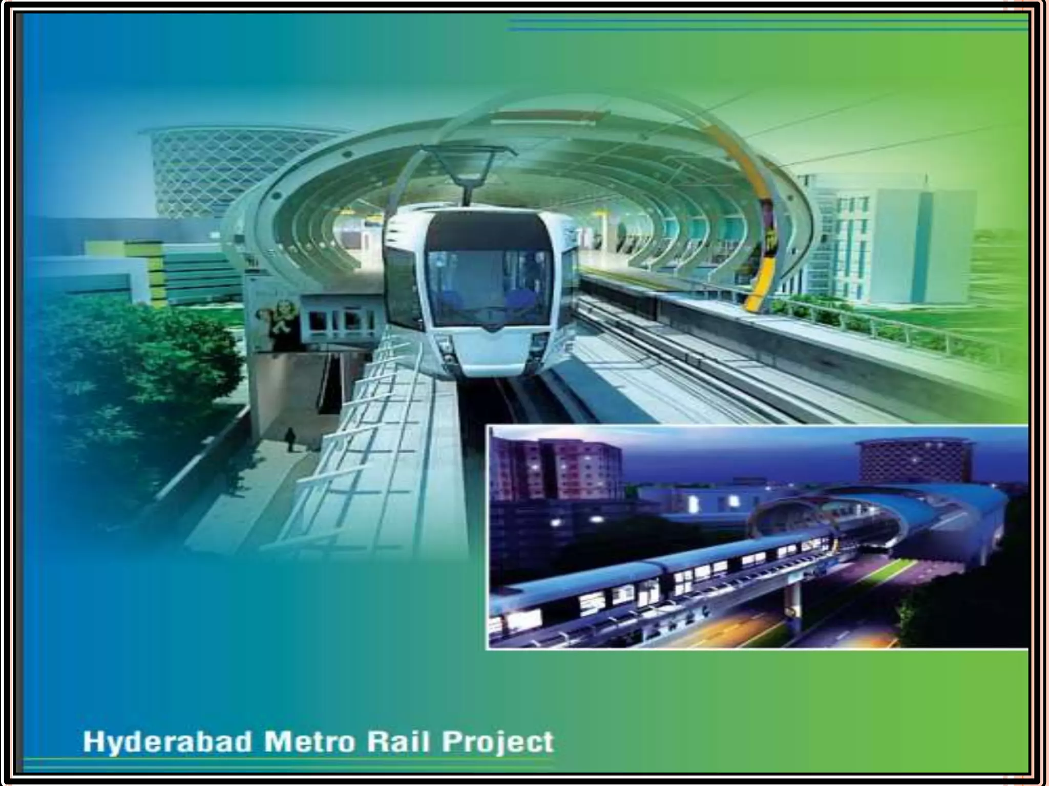
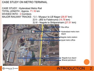
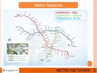
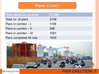
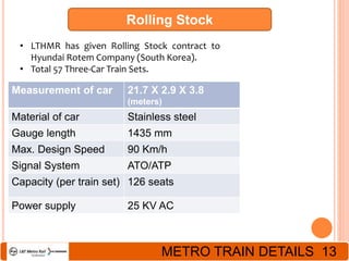
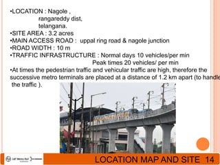
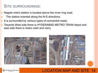
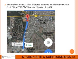
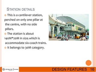
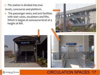
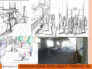
IMPORTANCE AND USE 1
 ARCHITECTURE OF HYDERABAD : Indo- Islamic Architecture.
 The city of Hyderabad- known for NIZAM rule, the architecture of hyderabad
reflects this architectural style.
 METRO STATION ARCHITECTURE (Hyderabad) : Indo- French
Architecture.
 French touch to Hyderabad metro rail project for the 1st time in Telangana.
 The passion of people of Hyderabad and Bordeaux have for their respective
cities, which brought the development to the city and at the same time keeping
its historical flavour alive.
 Metro development was a solution to the increasing population, pollution,
traffic etc.
 BENEFITS OF METRO RAIL:
 Fuel cost saving
 Number of vehicles off the road
 Vehicle cost saving
 Reduction in emission of greenhouse gases
 Emission cost saving
 Number of Road accidents avoided
INTRODUCTION 2
CASE STUDY ON METRO TERMINAL
CASE STUDY : Hyderabad Metro Rail
TOTAL LENGTH : Approx. 71.16 km
DIVIDED INTO : 3 Corridors
MAJOR RAILWAY TRACKS : 1) I - Miyapur to LB Nagar (28.87 km)
2) II - JBS to Falaknuma (14.78 km)
3) III - Nagole to Shilparamam (27.51 km)
Rta office
Hyderabad metro train
depot
Nagole metro station
Uppal metro office
Nagole bus depot
Bharat petroleum
Metro Network
CORRIDOR I - RED
CORRIDOR II - GREEN
CORRIDOR III - BLUE
METRO NETWORK 3
Financial Aspects
• Initially allotted to MAYTAS, but, was cancelled due to delay in
Financial closure.
• Allotted to L&T in PPP mode, DBFOT basis.
Total cost of Project Rs.14,320 Cr.
Central GOVT 10% of Total cost
L&T Metro Rail Hyderabad
limited
Remaining Total cost
State GOVT (Telangana) Ready to bear the extra cost
State GOVT (Andhra
Pradesh)
0%
PROJECT DETAILS 4
Structure - Overview
STRUCTURAL DETAIL 5
Foundation
• Soil Investigation
• Shifting of Services and Amenities
• Foundation
• Open foundation
• Pile foundation
Concrete/
Rock Breaker
Vibrator
Compactor
FOUNDATION DETAIL 6
Piers (Contd.)
Total distance covered 72 KM
Total no. of piers 2748
Piers in corridor – I 1109
Piers in corridor – II 588
Piers in corridor – III 1051
Piers completed till now 1635
Piers
PIER ERECTION 7
Bearings
• Bearings are used for resisting the rotatory loads
Bearings
STRUCTURAL DETAIL 8
Pre-Fabrication
Piers hold the viaduct, this is done by stringing and sticking the Segments
together
Segments
Gantry and Travel for Lifting and
Loading Segments in the Yard
CONSTRUCTION ON SITE 9
Pre-Cast Segments
• In gen, 10 Segments between 2 Piers, each Segment about 40 Tons.
• Placing Viaduct Segments with the help of Launching Gantry.
Traveler
For Lifting
And Shifting
Segments
Slings for holding
Viaduct Segments
Launching
Gantry
Viaduct Segments
under-slung during
Sticking and
Stitching process
P
I
E
R
VIADUCT PLACEMENTS 10
Pre-Cast Segments (Contd.)
Sticking the Pre-Cast Segments
Application of
Epoxy on
surface
of Segment
VIADUCT CONNECTIONS 11
Station Concept (Contd.)
• Stations are covered by an overlapping roofing system, open at
sides, covering the platform
• Staircases & Escalators designed based on
• Architectural Elements
• Functional Aspects.
Station Design
STATION CONCEPT 12
Rolling Stock
• LTHMR has given Rolling Stock contract to
Hyundai Rotem Company (South Korea).
• Total 57 Three-Car Train Sets.
Measurement of car 21.7 X 2.9 X 3.8
(meters)
Material of car Stainless steel
Gauge length 1435 mm
Max. Design Speed 90 Km/h
Signal System ATO/ATP
Capacity (per train set) 126 seats
Power supply 25 KV AC
METRO TRAIN DETAILS 13
NAGOLE METRO STATION
•LOCATION : Nagole ,
rangareddy dist,
telangana.
•SITE AREA : 3.2 acres
•MAIN ACCESS ROAD : uppal ring road & nagole junction
•ROAD WIDTH : 10 m
•TRAFFIC INFRASTRUCTURE : Normal days 10 vehicles/per min
Peak times 20 vehicles/ per min
•At times the pedestrian traffic and vehicular traffic are high, therefore the
successive metro terminals are placed at a distance of 1.2 km apart (to handle
the traffic ).
LOCATION MAP AND SITE 14
SITE SURROUNDINGS:
 Nagole metro station is located above the inner ring road.
 The station oriented along the N-S directions.
 It is surrounded by various types of connected roads.
 Towards West side there is HYDERABAD METRO TRAIN depot and
east side there is metro cash and carry.
LOCATION MAP AND SITE 14
 The another metro station is located nearer to nagole station which
is UPPAL METRO STATION at a distance of 1.2KM.
STATION SITE & SURROUNDINGS 15
STATION DETAILS
 This is a cantilever station,
perched on only one pillar at
the centre, with no side
pillars.
 The station is about
140M*20M in size.which is
accommodate six-coach trains.
 It belongs to 30M category.
DESIGN FEATURES 16
 The station is divided into two
levels, concourse and platform.
 The passenger entry and exit facilities
with stair cases, escalators and lifts.
Which is began at concourse level at a
height of 8M.
CIRCULATION SPACES 17
ARCHITECTURAL FEATURES
 The station is designed in
the form of SPINE and
WING,which resembles
a bird and 70% of it is
pre- fabricated.
 This is to avoid
inconvenience to road
Traffic.
 The openings on the either
sides of the station, do not
provide sufficient amount
of ventilation when the
space is heavily crowded.
 Unlike all the stations
the HMR stations are
completely ECO-FRIENDLY.
ARCHITECTURAL FEATURES 18
STATION ZONE WITH HEAVY TRAFFIC 19

Metro ppt - copy

  • 2.
    IMPORTANCE AND USE1  ARCHITECTURE OF HYDERABAD : Indo- Islamic Architecture.  The city of Hyderabad- known for NIZAM rule, the architecture of hyderabad reflects this architectural style.  METRO STATION ARCHITECTURE (Hyderabad) : Indo- French Architecture.  French touch to Hyderabad metro rail project for the 1st time in Telangana.  The passion of people of Hyderabad and Bordeaux have for their respective cities, which brought the development to the city and at the same time keeping its historical flavour alive.  Metro development was a solution to the increasing population, pollution, traffic etc.  BENEFITS OF METRO RAIL:  Fuel cost saving  Number of vehicles off the road  Vehicle cost saving  Reduction in emission of greenhouse gases  Emission cost saving  Number of Road accidents avoided
  • 3.
    INTRODUCTION 2 CASE STUDYON METRO TERMINAL CASE STUDY : Hyderabad Metro Rail TOTAL LENGTH : Approx. 71.16 km DIVIDED INTO : 3 Corridors MAJOR RAILWAY TRACKS : 1) I - Miyapur to LB Nagar (28.87 km) 2) II - JBS to Falaknuma (14.78 km) 3) III - Nagole to Shilparamam (27.51 km) Rta office Hyderabad metro train depot Nagole metro station Uppal metro office Nagole bus depot Bharat petroleum
  • 4.
    Metro Network CORRIDOR I- RED CORRIDOR II - GREEN CORRIDOR III - BLUE METRO NETWORK 3
  • 5.
    Financial Aspects • Initiallyallotted to MAYTAS, but, was cancelled due to delay in Financial closure. • Allotted to L&T in PPP mode, DBFOT basis. Total cost of Project Rs.14,320 Cr. Central GOVT 10% of Total cost L&T Metro Rail Hyderabad limited Remaining Total cost State GOVT (Telangana) Ready to bear the extra cost State GOVT (Andhra Pradesh) 0% PROJECT DETAILS 4
  • 6.
  • 7.
    Foundation • Soil Investigation •Shifting of Services and Amenities • Foundation • Open foundation • Pile foundation Concrete/ Rock Breaker Vibrator Compactor FOUNDATION DETAIL 6
  • 8.
    Piers (Contd.) Total distancecovered 72 KM Total no. of piers 2748 Piers in corridor – I 1109 Piers in corridor – II 588 Piers in corridor – III 1051 Piers completed till now 1635 Piers PIER ERECTION 7
  • 9.
    Bearings • Bearings areused for resisting the rotatory loads Bearings STRUCTURAL DETAIL 8
  • 10.
    Pre-Fabrication Piers hold theviaduct, this is done by stringing and sticking the Segments together Segments Gantry and Travel for Lifting and Loading Segments in the Yard CONSTRUCTION ON SITE 9
  • 11.
    Pre-Cast Segments • Ingen, 10 Segments between 2 Piers, each Segment about 40 Tons. • Placing Viaduct Segments with the help of Launching Gantry. Traveler For Lifting And Shifting Segments Slings for holding Viaduct Segments Launching Gantry Viaduct Segments under-slung during Sticking and Stitching process P I E R VIADUCT PLACEMENTS 10
  • 12.
    Pre-Cast Segments (Contd.) Stickingthe Pre-Cast Segments Application of Epoxy on surface of Segment VIADUCT CONNECTIONS 11
  • 13.
    Station Concept (Contd.) •Stations are covered by an overlapping roofing system, open at sides, covering the platform • Staircases & Escalators designed based on • Architectural Elements • Functional Aspects. Station Design STATION CONCEPT 12
  • 14.
    Rolling Stock • LTHMRhas given Rolling Stock contract to Hyundai Rotem Company (South Korea). • Total 57 Three-Car Train Sets. Measurement of car 21.7 X 2.9 X 3.8 (meters) Material of car Stainless steel Gauge length 1435 mm Max. Design Speed 90 Km/h Signal System ATO/ATP Capacity (per train set) 126 seats Power supply 25 KV AC METRO TRAIN DETAILS 13
  • 15.
  • 16.
    •LOCATION : Nagole, rangareddy dist, telangana. •SITE AREA : 3.2 acres •MAIN ACCESS ROAD : uppal ring road & nagole junction •ROAD WIDTH : 10 m •TRAFFIC INFRASTRUCTURE : Normal days 10 vehicles/per min Peak times 20 vehicles/ per min •At times the pedestrian traffic and vehicular traffic are high, therefore the successive metro terminals are placed at a distance of 1.2 km apart (to handle the traffic ). LOCATION MAP AND SITE 14
  • 17.
    SITE SURROUNDINGS:  Nagolemetro station is located above the inner ring road.  The station oriented along the N-S directions.  It is surrounded by various types of connected roads.  Towards West side there is HYDERABAD METRO TRAIN depot and east side there is metro cash and carry. LOCATION MAP AND SITE 14
  • 18.
     The anothermetro station is located nearer to nagole station which is UPPAL METRO STATION at a distance of 1.2KM. STATION SITE & SURROUNDINGS 15
  • 19.
    STATION DETAILS  Thisis a cantilever station, perched on only one pillar at the centre, with no side pillars.  The station is about 140M*20M in size.which is accommodate six-coach trains.  It belongs to 30M category. DESIGN FEATURES 16
  • 20.
     The stationis divided into two levels, concourse and platform.  The passenger entry and exit facilities with stair cases, escalators and lifts. Which is began at concourse level at a height of 8M. CIRCULATION SPACES 17
  • 21.
    ARCHITECTURAL FEATURES  Thestation is designed in the form of SPINE and WING,which resembles a bird and 70% of it is pre- fabricated.  This is to avoid inconvenience to road Traffic.  The openings on the either sides of the station, do not provide sufficient amount of ventilation when the space is heavily crowded.  Unlike all the stations the HMR stations are completely ECO-FRIENDLY. ARCHITECTURAL FEATURES 18
  • 22.
    STATION ZONE WITHHEAVY TRAFFIC 19