The document provides details about the Bangalore Metro Rail Project, including:
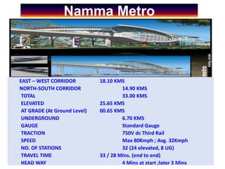
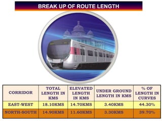
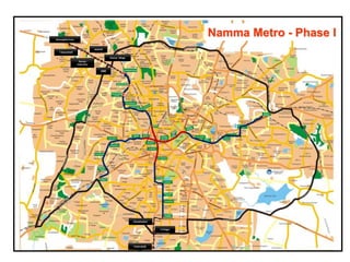
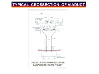
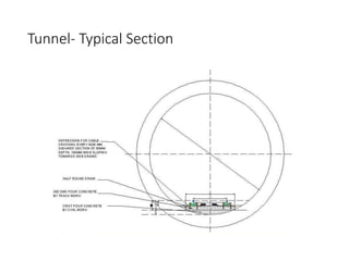
- The East-West and North-South corridors will have a total length of 33kms, with 25.65kms elevated, 0.65kms at ground level, and 6.7kms underground.
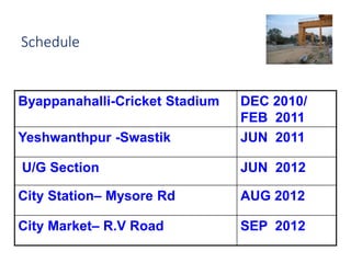
- Phase 1 will connect the stations of Byappanahalli to Swastik with underground sections opening by 2012.
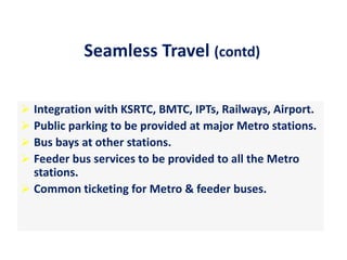
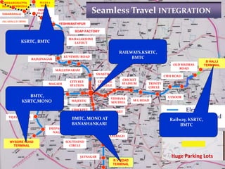
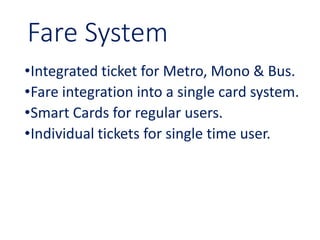
- Seamless travel integration is planned with other transit modes like KSRTC, BMTC, Railways and the Airport through coordination on ticketing, bus bays, and feeder services.
![Utilization of Electrical Power [18EE742]
Beyond Syllabus
Topic: BMRCL
By:
Dr. J P Sridhar
Associate Professor
EEE Department
SJB Institute of Technology
Date: 31/10/2022](https://image.slidesharecdn.com/epubeyondsyllabus1bmrcl-230329033003-3c6ebbc5/85/BMRCL-ppt-1-320.jpg)