Downloaded 111 times

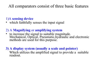

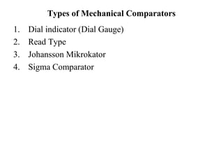
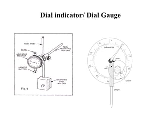

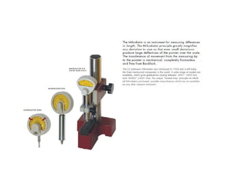

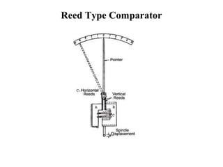
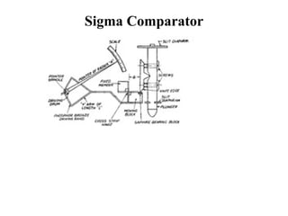
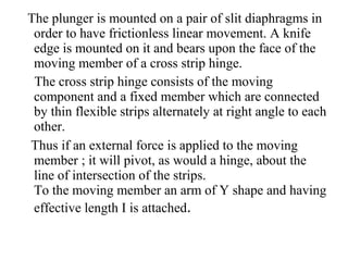

Mechanical comparators indicate differences in size between a standard and workpiece using a pointer on a magnified scale. They have three basic features - a sensing device, magnifying system, and display scale/pointer. Common types include dial indicators, reed, and sigma comparators. Dial indicators use a plunger and dial gauge. Reed comparators use a frictionless reed mechanism to magnify spindle motion. Sigma comparators use a knife edge and cross strip hinge arrangement. Advantages are low cost and portability while disadvantages include friction, slackness reducing accuracy, and limited range.