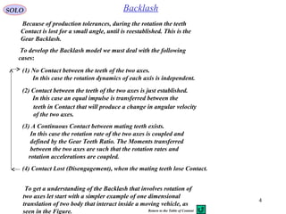
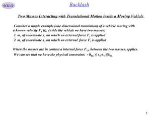
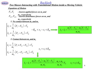
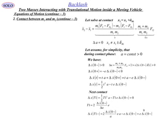
Downloaded 103 times
![7
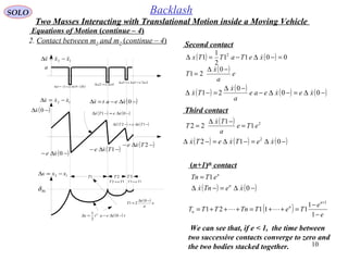
SOLO Backlash
Equations of Motion (continue – 1)
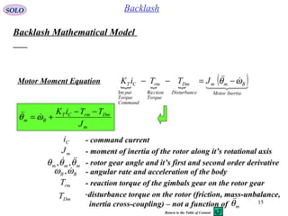
At collision between m1 and m2 a transfer of linear impulse ΔP occurs between the two masses
( )( ) ( )( )[ ] ( )( ) ( )( )[ ]
( ) ( )[ ] ( ) ( )[ ]−−+−=−−+=
−+−++−=−+−++=∆=∆
222111
22211112
xxmxxm
xVxVmxVxVmtFP BBBB
or
( ) ( )[ ] ( ) ( )[ ] 0222111 =−−++−−+ xxmxxm
The second equation is obtained by using the elastic coefficient
of collision e (e = 0, for plastic collision and e =1 for an elastic
collision), that is defined as:
We obtain one equation with two unknowns ( ) ( )++ 21 , xx
( ) ( )
( ) ( )
( )[ ] ( )[ ]
( )[ ] ( )[ ]−+−−+
++−++
−=
−−−
+−+
−=
21
21
21
21
:
xVxV
xVxV
VV
VV
e
BB
BB
( ) ( )
( ) ( )−−−
+−+
−=
21
21
xx
xx
e
or
We have x2 = x1 - δBL if before contact (-) ( ) ( ) 012 <−−− xx
We have x2 = x1 +δBL if before contact (-) ( ) ( ) 012 >−−− xx
2. Contact between m1 and m2 (continue – 1)
Two Masses Interacting with Translational Motion inside a Moving Vehicle](https://image.slidesharecdn.com/2-backlashsimulation-141227085426-conversion-gate01/85/2-backlash-simulation-7-320.jpg)
![8
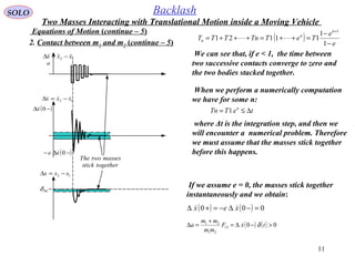
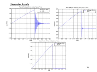
SOLO Backlash
Equations of Motion (continue – 2)
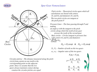
Now we have two equations with two unknowns:
or
Solving for , we obtain:( ) ( )++ 21 ,xx
( ) ( ) ( ) ( ) ( ) ( )−++−−=++ 22121121 1 xmexemmxmm
( ) ( ) ( ) ( ) ( ) ( )−−+−+=++ 21211221 1 xemmxmexmm
( ) ( ) ( )
( )
( ) ( )[ ]−−−
+
+
+−=+ 12
21
2
11
1
xx
mm
me
xx
( ) ( ) ( )
( )
( ) ( )[ ]−−−
+
+
−−=+ 12
21
1
22
1
xx
mm
me
xx
2. Contact between m1 and m2 (continue – 2)
( )
( )
( ) ( )[ ]−−−
+
+
=∆=∆ 12
21
21
12
1
xx
mm
mme
tFP ( ) ( )[ ] ( ) ( )[ ]−−+−=−−+=∆=∆ 22211112 xxmxxmtFP or
1F
2m
1x
2x
BV
1m
BLδ
1 2
P∆P∆
BLδ
0&12 >∆=− Pxx BLδ
2F
( ) ( ) ( ) ( )
( ) ( ) ( ) ( )−−−=+−+
−+−=+++
1221
22112211
xexexx
xmxmxmxm
Two Masses Interacting with Translational Motion inside a Moving Vehicle](https://image.slidesharecdn.com/2-backlashsimulation-141227085426-conversion-gate01/85/2-backlash-simulation-8-320.jpg)
![14
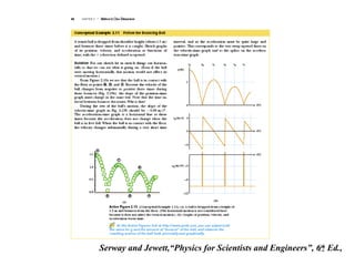
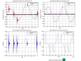
SOLO Backlash
Equations of Motion (continue – 7)
1F
1DF
12F
12F
2DF
12F
2F
( ) ( ) ( )
( )
( ) ( )[ ]−−−
+
+
−−=+ 12
21
1
22
1
xx
mm
me
xx
2
1
m s
1
s
1
BV
2x
BL
( ) ( ) ( )
( )
( ) ( )[ ]−−−
+
+
+−=+ 12
21
2
11
1
xx
mm
me
xx
1
1
m s
1
s
1
BV
1x
BL
( )
( ) ( )
( )11
21
2
2
21
1
2 DD FF
mm
m
FF
mm
m
−
+
−−
+
2x
12 xx −
BL
1
0 12 xx −
BLδBLδ−
1x
2x
12F
( )121 2 xxF −
1 ( )[ ]1212 xxFsign −
AND
BL
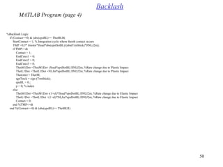
Stick
mode
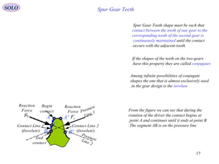
Two Masses Interacting with Translational Motion inside a Moving Vehicle
Return to the Table of Content](https://image.slidesharecdn.com/2-backlashsimulation-141227085426-conversion-gate01/85/2-backlash-simulation-14-320.jpg)
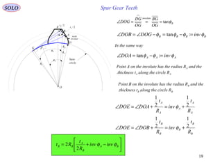
![23
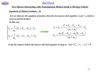
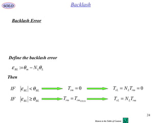
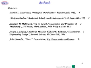
SOLO Backlash
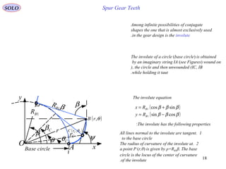
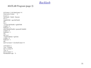
From this equation we can find the moment Trm necessary to stick the
motor gear to the gimbals gear is:
L
LDL
BB
m
DmrmCT
LL
L
L
rL
rm
N
TT
J
TTiK
NN
J
N
T
T
+
+
+
+
−−
== ωω
1
( )[ ] ( )
2
2
1
1
1
1
LmL
LDLmLBLmDmCTL
Lm
L
L
LDL
BB
m
DmCT
LL
L
rm
NJJ
TTJNNJTiKJ
NJ
J
N
TT
J
TiK
NN
J
T STICK
+
++++−
=
+
+
+
+
+
−
=
ω
ωω
m
DmrmCT
Bm
J
TTiK −−
=−ωθ
L
LDLrmL
BL
J
TTTN −−
=+ωθ
Contact Moment
Return to the Table of Content](https://image.slidesharecdn.com/2-backlashsimulation-141227085426-conversion-gate01/85/2-backlash-simulation-23-320.jpg)
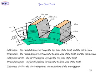
![26
SOLO Backlash
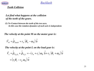
The collision between toot M and L will produce an equal and opposite
impulse Pr on the gear tooth, that will produce reaction impulses on the gear
axes, and a change in angular impulse on both gears (ΔHm, ΔHL)
( )[ ] ( )[ ]
( ) ( )[ ] mrmmm
BmmBmmm
rPJ
JJH
∆−=−−+=
−−−−+=∆
θθ
ωθωθ
( )[ ] ( )[ ]
( ) ( )[ ] LrLLL
BLLBLLL
rPJ
JJH
∆=−−+=
+−−++=∆
θθ
ωθωθ
( ) ( )−− Lm θθ , and are the angular
rates of the motor and gimbals gears, respectively,
before (-) and after(+) the collision.
( ) ( )++ Lm θθ ,
We obtain the following equations
( ) ( )[ ] ( ) ( )[ ]−−+−=−−+=∆ mmm
m
LLL
L
r J
r
J
r
P θθθθ 11
Teeth collision (continue – 1)](https://image.slidesharecdn.com/2-backlashsimulation-141227085426-conversion-gate01/85/2-backlash-simulation-26-320.jpg)
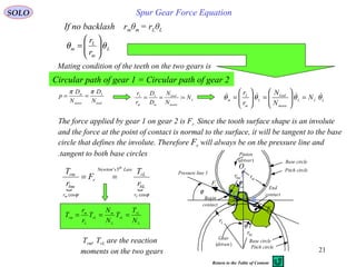
![27
SOLO Backlash
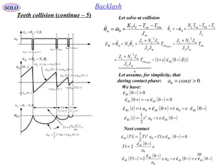
The second equation is obtained by using the
elastic coefficient of collision e (e = 0, for plastic
collision and e =1 for an elastic collision), that is
defined as:
( ) ( )[ ] ( ) ( )[ ]−−+−=−−+=∆ mmm
m
LLL
L
r J
r
J
r
P θθθθ 11
or
( ) ( )[ ] ( ) ( )[ ] 0=−−++−−+ mmmLLLL JNJ θθθθ
We obtain one equation with two unknowns ( ) ( )++ Lm θθ ,
( ) ( )
( ) ( )
( )[ ] ( )[ ]
( )[ ] ( )[ ]
( ) ( )
( ) ( )
( ) ( )
( ) ( )−−−
+−+
−=
−−−
+−+
−=
−−−−−
−+−−+
−=
−−−
+−+
−=
mLL
mLL
mmLL
mmLL
BmmmBmLL
BmmmBmLL
ML
ML
N
N
rr
rr
rrrr
rrrr
VV
VV
e
θθ
θθ
θθ
θθ
ωθωθ
ωθωθ
:
Teeth collision (continue – 2)](https://image.slidesharecdn.com/2-backlashsimulation-141227085426-conversion-gate01/85/2-backlash-simulation-27-320.jpg)
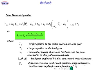
![28
SOLO Backlash
or:
Now we have two equations with two unknowns ( ) ( )++ Lm θθ ,
( ) ( ) ( ) ( )
( ) ( ) ( ) ( )
−−−=+++−
−+−=+++
LLmLLm
LLmmLLLmmL
eNeN
JJNJJN
θθθθ
θθθθ
Solving for we obtain( ) ( )++ Lm θθ ,
( ) ( ) ( ) ( ) ( ) ( )
( ) ( ) ( ) ( ) ( ) ( )−−+−+=++
−++−−=++
LmLLmmLGmLL
LLLmLmLmmLL
JNeJJNeJNJ
JNeJeJNJNJ
θθθ
θθθ
22
22
1
1
( ) ( ) ( )
( ) ( ) ( )[ ]−−−
+
+
−−=+ LLm
mLL
L
mm N
JNJ
Je
θθθθ
2
1
( ) ( ) ( )
( ) ( ) ( )[ ]−−−
+
+
+−=+ LLm
mLL
mL
LL N
JNJ
JNe
θθθθ
2
1
Teeth collision (continue – 3)
Also
( ) ( )[ ] ( ) ( ) ( )[ ]−−−
+
+
=−−+−=∆=∆ LLm
mLL
Lm
mmmmrrm N
JNJ
JJe
JrPtT C
θθθθ
2
1](https://image.slidesharecdn.com/2-backlashsimulation-141227085426-conversion-gate01/85/2-backlash-simulation-28-320.jpg)
![29
SOLO Backlash
Let compute ( ) ( )+−+ LLm N θθ
( ) ( ) ( )
( ) ( ) ( )[ ]−−−
+
+
−−=+ LLm
mLL
L
mm N
JNJ
Je
θθθθ
2
1
( ) ( ) ( )
( ) ( ) ( )[ ]−−−
+
+
+−=+ LLm
mLL
mL
LL N
JNJ
JNe
θθθθ
2
1
Teeth collision (continue – 4)
( ) ( ) ( )
( )
( )
( ) ( ) ( )[ ]−−−
+
+
−
+
+
−=+−+ LLm
mLL
mL
mLL
L
LLm N
JNJ
JNe
JNJ
Je
N θθθθ
2
2
2
11
1
or
( ) ( ) ( ) ( )[ ]−−−−=+−+ LLmLLm NeN θθθθ
We can see that
( ) ( )[ ] ( ) ( )[ ]−−−−=+−+ LLmLLm NsignNsign θθθθ ](https://image.slidesharecdn.com/2-backlashsimulation-141227085426-conversion-gate01/85/2-backlash-simulation-29-320.jpg)
![31
SOLO Backlash
The kinetic energy loss due to the collision is given by
( ) ( ) ( ) ( )
2
2222
2
1
2
1
2
1
2
1
+++−
−+−=∆ LLmmLLmmk JJJJE θθθθ
( ) ( )
( ) ( )
( ) ( ) ( )[ ]
( ) ( )
( ) ( ) ( )[ ]
2
2
2
2
22
1
2
1
1
2
1
2
1
2
1
−−−
+
+
+−−
−−−
+
+
−−−
−+−=
LLm
mLL
mL
LL
LLm
mLL
L
mm
LLmm
N
JNJ
JNe
J
N
JNJ
Je
J
JJ
θθθ
θθθ
θθ
( )
( ) ( ) ( )[ ] ( ) ( )[ ]
( )
( )
( ) ( )[ ] ( )mLLLLm
mLL
mL
LLmLLm
mLL
mL
JNJN
JNJ
JJe
NN
JNJ
JJe
22
22
2
2
2
1
1
+−−−
+
+
−
−−−−−−
+
+
−=
θθ
θθθθ
( )
( ) ( ) ( )[ ]2
2
2
2
1
−−−
+
−
= LLm
mLL
mL
N
JNJ
JJe
θθ
Teeth collision (continue – 6)](https://image.slidesharecdn.com/2-backlashsimulation-141227085426-conversion-gate01/85/2-backlash-simulation-31-320.jpg)
![32
SOLO Backlash
The kinetic energy loss due to the collision is given by
( )
( ) ( ) ( )[ ]2
2
2
2
1
−−−
+
−
=∆ LLm
mLL
mL
k N
JNJ
JJe
E θθ
We can see that
1. If (soft touch) then( ) ( )−=− mLLN θθ
( ) ( )−=+ mm θθ
( ) ( )−=+ LL θθ
0=∆ kE
2. If e = 1 (elastic collision)
0=∆ kE
3. The maximum kinetic energy loss is obtained when e = 0 (plastic collision)
( ) ( ) ( )[ ]2
2
2
−−−
+
=∆ LLm
mLL
mL
k N
JNJ
JJ
E MAX
θθ
Teeth collision (continue – 7)
Return to the Table of Content](https://image.slidesharecdn.com/2-backlashsimulation-141227085426-conversion-gate01/85/2-backlash-simulation-32-320.jpg)
![36
SOLO Backlash
Dynamic computations in contact
Compute
Contact Flag = .True.
[ ]
mr
LmL
DLmLBmDmCTL
rm rF
NJJ
TJNJTiKJ
T STICK
=
+
++−
= 2
ω
m
DmrmCT
Bm
J
TTiK −−
=−ωθ
L
LDLrmL
BL
J
TTTN +−
=+ωθ
Integrate both equations to obtain
BLBm ωθωθ +− ,
Compute and integrate to obtainLm θθ , Lm θθ ,
Backlash Logic (continue - 3)](https://image.slidesharecdn.com/2-backlashsimulation-141227085426-conversion-gate01/85/2-backlash-simulation-36-320.jpg)
![37
SOLO Backlash
Dynamic computations in contact (second way)
Compute
Contact Flag = .True.
[ ]
mr
LmL
DLmLBmDmCTL
rm rF
NJJ
TJNJTiKJ
T STICK
=
+
++−
= 2
ω
B
m
DmrmCT
m
J
TTiK
ωθ +
−−
=
B
L
LDLrmL
L
J
TTTN
ωθ −
+−
=
Integrate both equations to obtain
Lm θθ ,
and integrate to obtain Lm θθ ,
Backlash Logic (continue - 4)](https://image.slidesharecdn.com/2-backlashsimulation-141227085426-conversion-gate01/85/2-backlash-simulation-37-320.jpg)
![40
SOLO Backlash
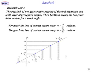
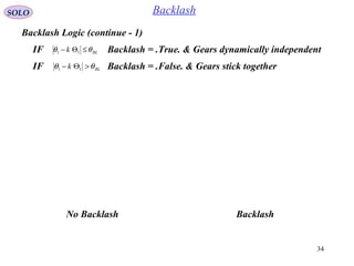
Backlash Logic (continue - 7)
Contact Between Gears Teeth is Detected
( )[ ] ( )
mr
LmL
LDLmLBLmDmCTL
rm rF
NJJ
TTJNNJTiKJ
T STICK
=
+
++++−
= 2
1 ω
Compute
( ) ( ) ( )
( ) ( ) ( )[ ]−−−
+
+
+−=+ mLL
mLL
L
mm N
JNJ
Je
θθθθ
2
1
( ) ( ) ( )
( ) ( ) ( )[ ]−−−
+
+
−−=+ mLL
mLL
mL
LL N
JNJ
JNe
θθθθ
2
1
on pressure line 1 if
210 GG →>θ
120 GG →<θIf 0>= mrrm rFT STICK
Contact begins at point A
Contact begins at point B
on pressure line 2 if
120 GG →>θ
210 GG →<θ
If 0<= mrrm rFT STICK
Contact begins at point C
Contact begins at point D
Contact Start changes from .False. to .True.
Store ( ) mθθ =+
Reinitialize the integrators using](https://image.slidesharecdn.com/2-backlashsimulation-141227085426-conversion-gate01/85/2-backlash-simulation-40-320.jpg)
![41
SOLO Backlash
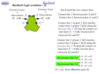
Backlash Logic (continue - 8)
When Contact Start = .True. the elastic collisions
between gears teeth will occur and the time
between two successive collisions will be
( )
e
a
T
T nBL
n
θ
ε
2
1 −
= −
LLmBL N θθε −=
θa
BLθ
( )−0BLε
The two gears
stick together
LLmBL N θθε −=
( )−− 0BLe ε
LLmBL N θθε −=
1−nT nT
( )
e
a
T
T NBL
n
θ
ε
2
1 −
= −
We can see that if e=0 (plastic collision),
we have T1 = 0 and the teeth remain in
contact. In this case
Contact Flag = .True.
when Contact Start = .True.
0=eIf
( ) ( ) ( )
( ) ( ) ( )[ ]
0
2
1
=
−−−
+
+
+−=+
e
mLL
mLL
L
mm N
JNJ
Je
θθθθ
( ) ( ) ( )
( ) ( ) ( )[ ]
0
2
1
=
−−−
+
+
−−=+
e
mLL
mLL
mL
LL N
JNJ
JNe
θθθθ
STICKrm
mLL
Lm
T
JNJ
JJ
a 2
+
=θ
Contact Between Gears Teeth is Detected (continue - 1)
Reinitialize the integrators using](https://image.slidesharecdn.com/2-backlashsimulation-141227085426-conversion-gate01/85/2-backlash-simulation-41-320.jpg)
![42
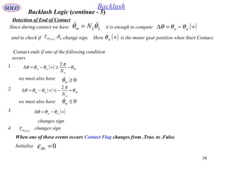
SOLO Backlash
To prevent numerical problems, when
Contact Flag = .True.
Backlash Logic (continue - 9)
When Contact Start = .True. the elastic collisions
between gears teeth will occur and the time
between two successive collisions will be
( )
e
a
T
T nBL
n
θ
ε
2
1 −
= −
LLmBL N θθε −=
θa
BLθ
( )−0BLε
The two gears
stick together
LLmBL N θθε −=
( )−− 0BLe ε
LLmBL N θθε −=
1−nT nT
( )
e
a
T
T NBL
n
θ
ε
2
1 −
= −
tTn ∆≤
(where Δt is related to the integration
time), we say that the two gears teeth are
in continuous contact and we declare
To assure that the teeth gears are in
continuous contact, we will reinitialize
using e=0, for this
computation cycle.
( ) ( )++ 0,0 Lm θθ
( ) ( ) ( )
( ) ( ) ( )[ ]
0
2
1
=
−−−
+
+
+−=+
e
mLL
mLL
L
mm N
JNJ
Je
θθθθ
( ) ( ) ( )
( ) ( ) ( )[ ]
0
2
1
=
−−−
+
+
−−=+
e
mLL
mLL
mL
LL N
JNJ
JNe
θθθθ
0≠eIf
STICKrm
mLL
Lm
T
JNJ
JJ
a 2
+
=θ
Return to the Table of Content
Contact Between Gears Teeth is Detected (continue - 2)](https://image.slidesharecdn.com/2-backlashsimulation-141227085426-conversion-gate01/85/2-backlash-simulation-42-320.jpg)
![45
SOLO Backlash
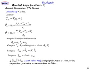
Backlash Logic (continue - 10)
When Contact Start = .True. instead of
performing reinitialization of integrals we can,
for one computation cycle, simulate the impulse
at collision.
LLmBL N θθε −=
θa
BLθ
( )−0BLε
The two gears
stick together
LLmBL N θθε −=
( )−− 0BLe ε
LLmBL N θθε −=
1−nT nT
( )
e
a
T
T NBL
n
θ
ε
2
1 −
= −
by using
Contact between gears is detected (continue - 1)
( ) ( ) ( )[ ]−−−
+
+
=∆=∆ LLm
mLL
Lm
mrrm N
JNJ
JJe
rPtT C
θθ
2
1
( ) ( ) ( )[ ]−−−
+
+
∆
= LLm
mLL
Lm
rm N
JNJ
JJe
t
T C
θθ
2
11](https://image.slidesharecdn.com/2-backlashsimulation-141227085426-conversion-gate01/85/2-backlash-simulation-45-320.jpg)


The document presents a mathematical model of gear backlash, detailing the interaction of two masses under translational motion within a moving vehicle. It explains the different scenarios of gear contact and the corresponding equations of motion, emphasizing the implications of production tolerances leading to backlash. Additionally, it discusses the impact of gear engagement and disengagement on motion dynamics, providing examples and equations related to the transfer of forces and moments during these interactions.


![Polymer [ बहुलक ] Chemistry Notes PDF - Irfanullah Mehar - JJ Sir Chemistry.pdf](https://cdn.slidesharecdn.com/ss_thumbnails/polymerchemistrynotespdf-irfanullahmehar-jjsirchemistry-260210172118-3f9b37f7-thumbnail.jpg?width=640&height=640&fit=bounds)
