Download as PDF, PPTX


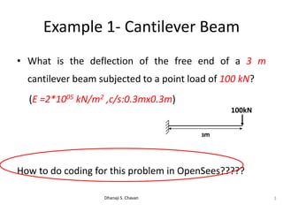
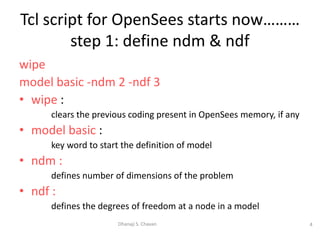
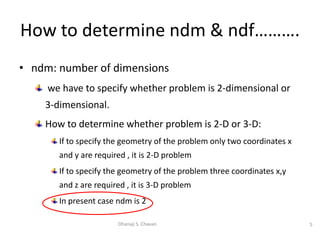
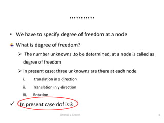
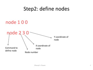
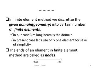
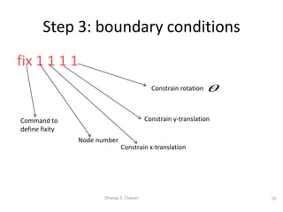
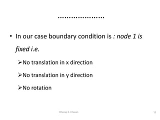
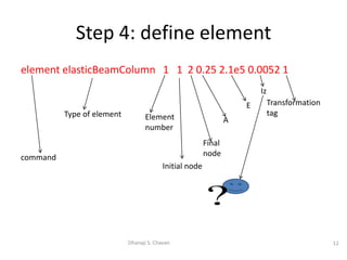
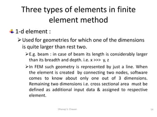
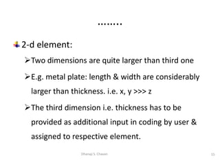
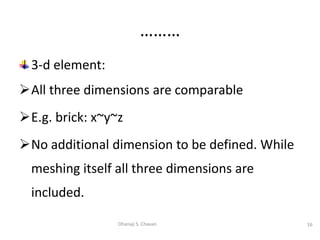
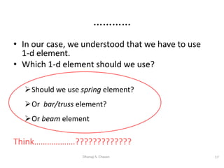

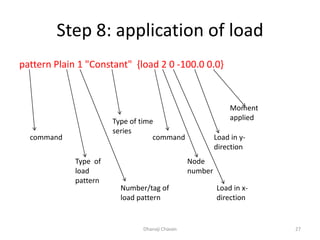
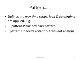
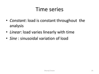
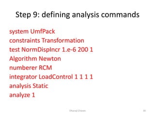
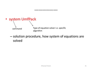
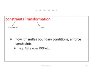
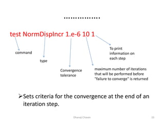
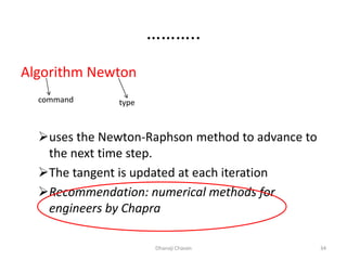
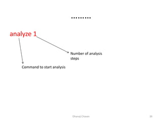
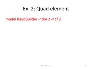
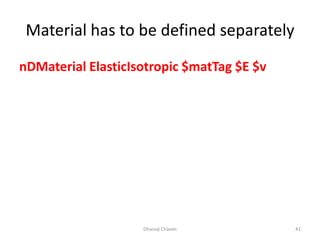
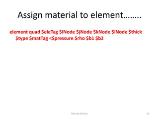

This document provides steps for modeling and performing static analysis in OpenSees. It begins with general steps like defining nodes, elements, materials, boundary conditions, and analysis objects. Then it provides an example of coding for a cantilever beam problem in OpenSees. Key steps in the example include defining two nodes, fixing the first node, using an elastic beam column element, applying a point load, and running the analysis to obtain the deflection of the free end. The document also discusses considerations for choosing appropriate elements and defines terms used in finite element modeling like degrees of freedom.