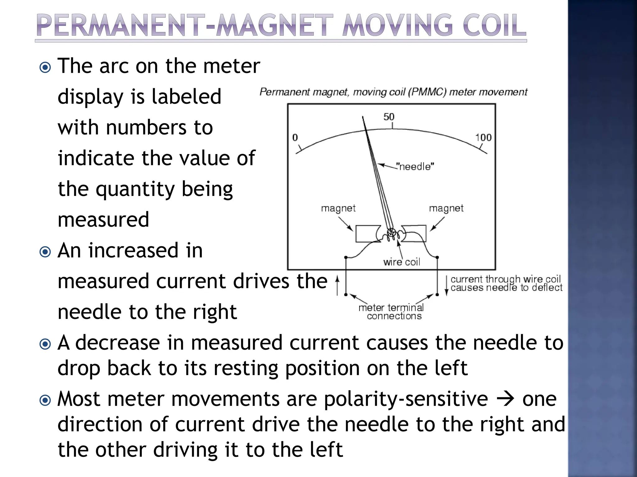
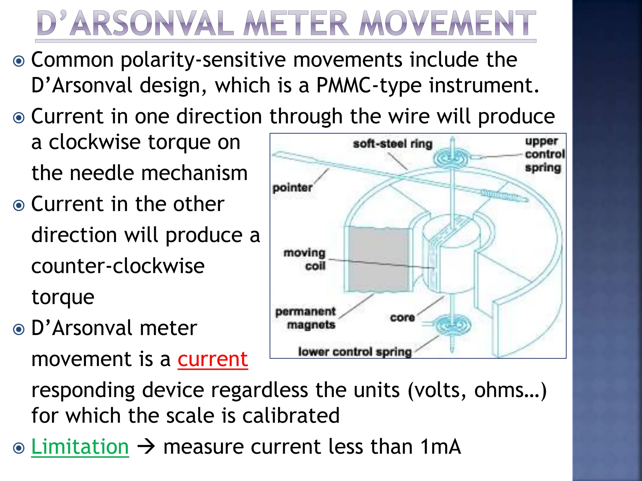
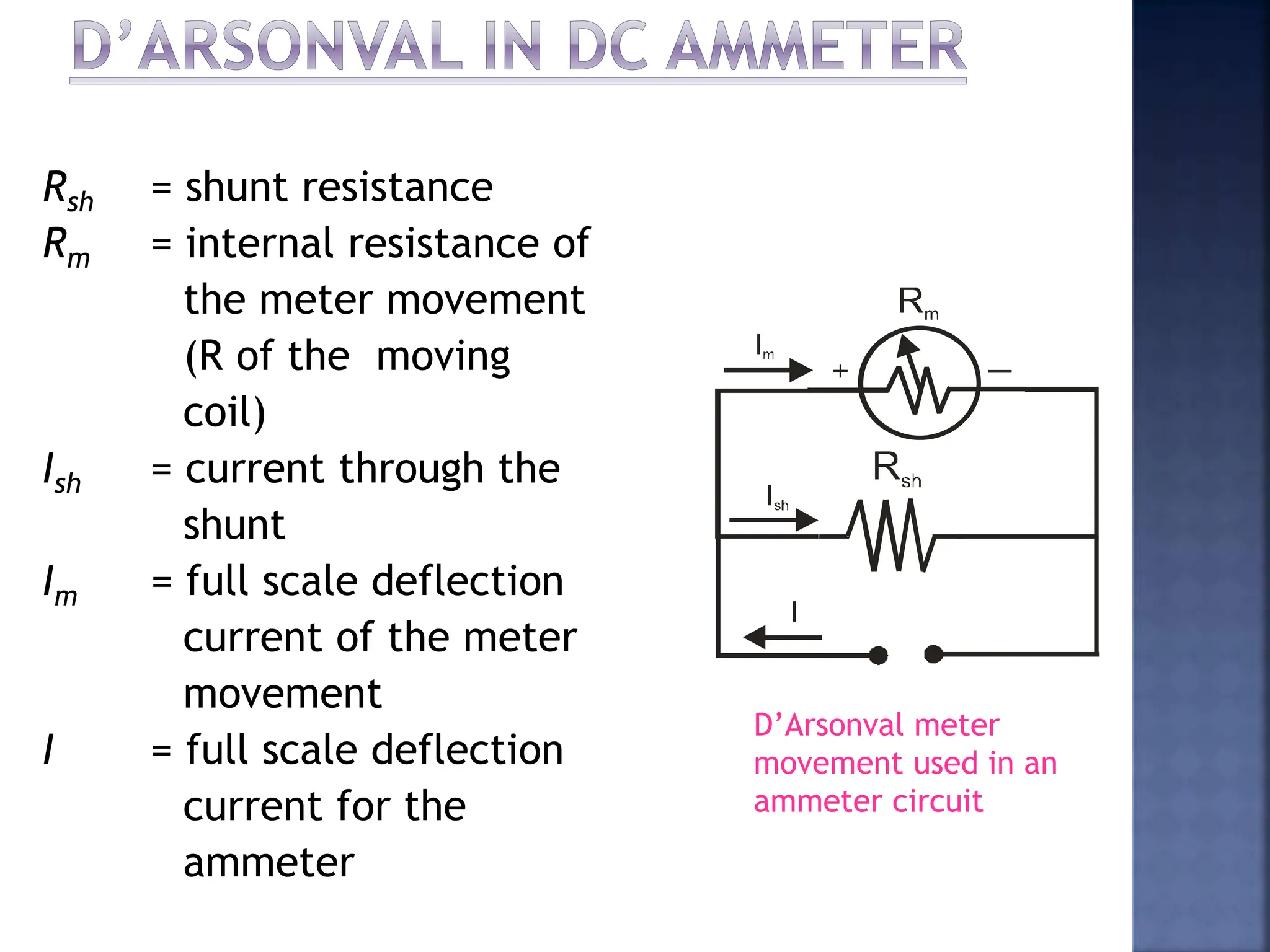
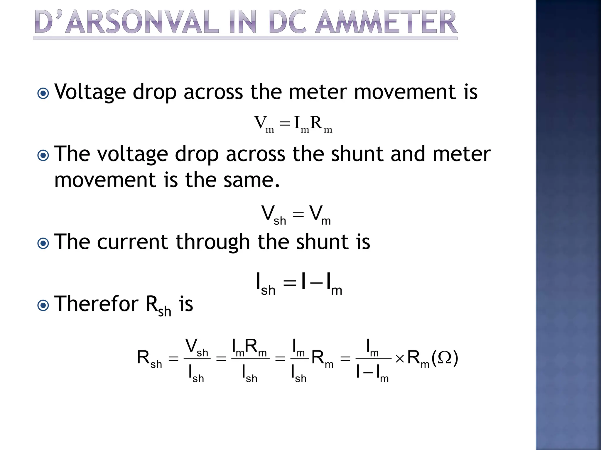
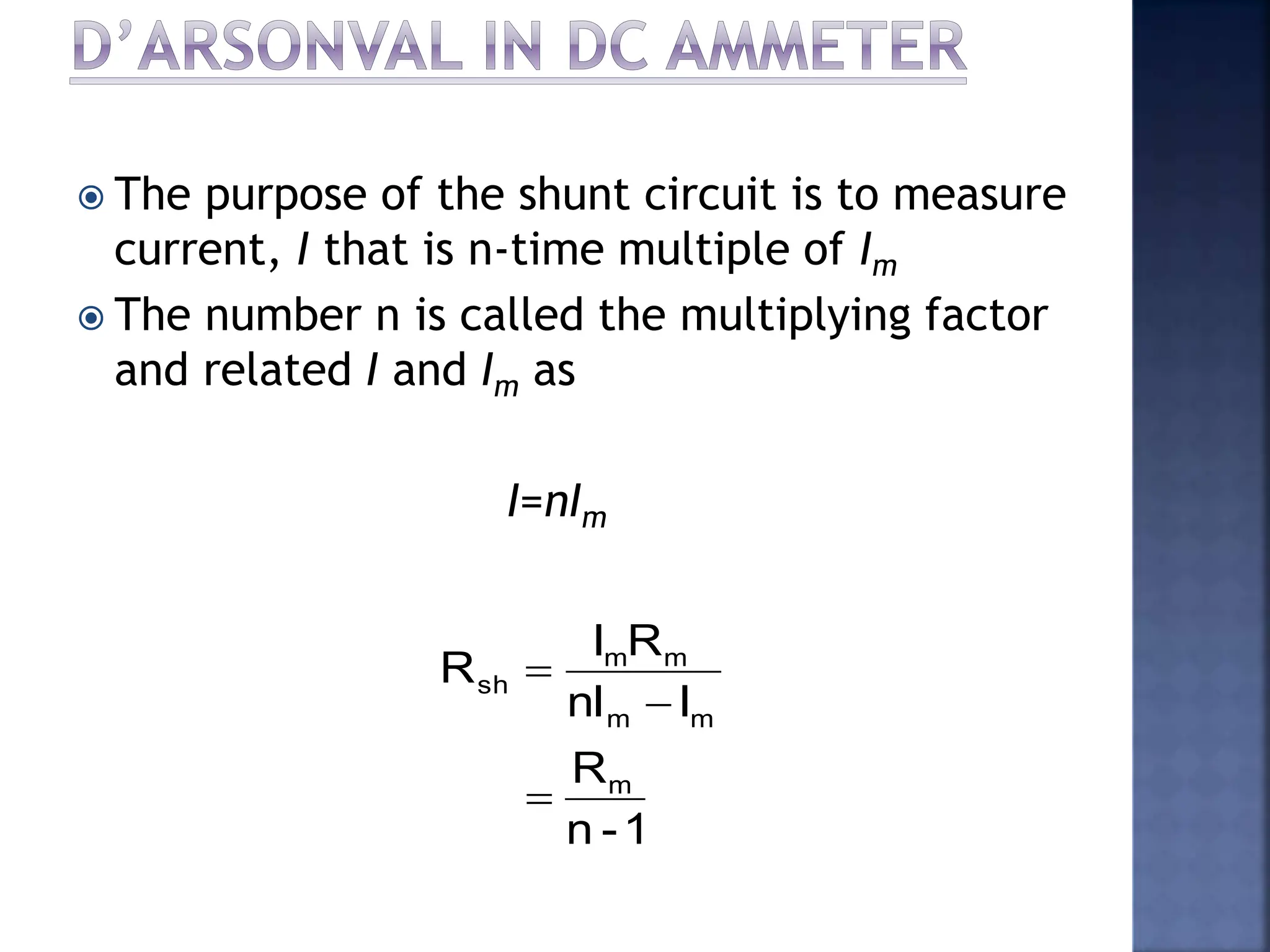
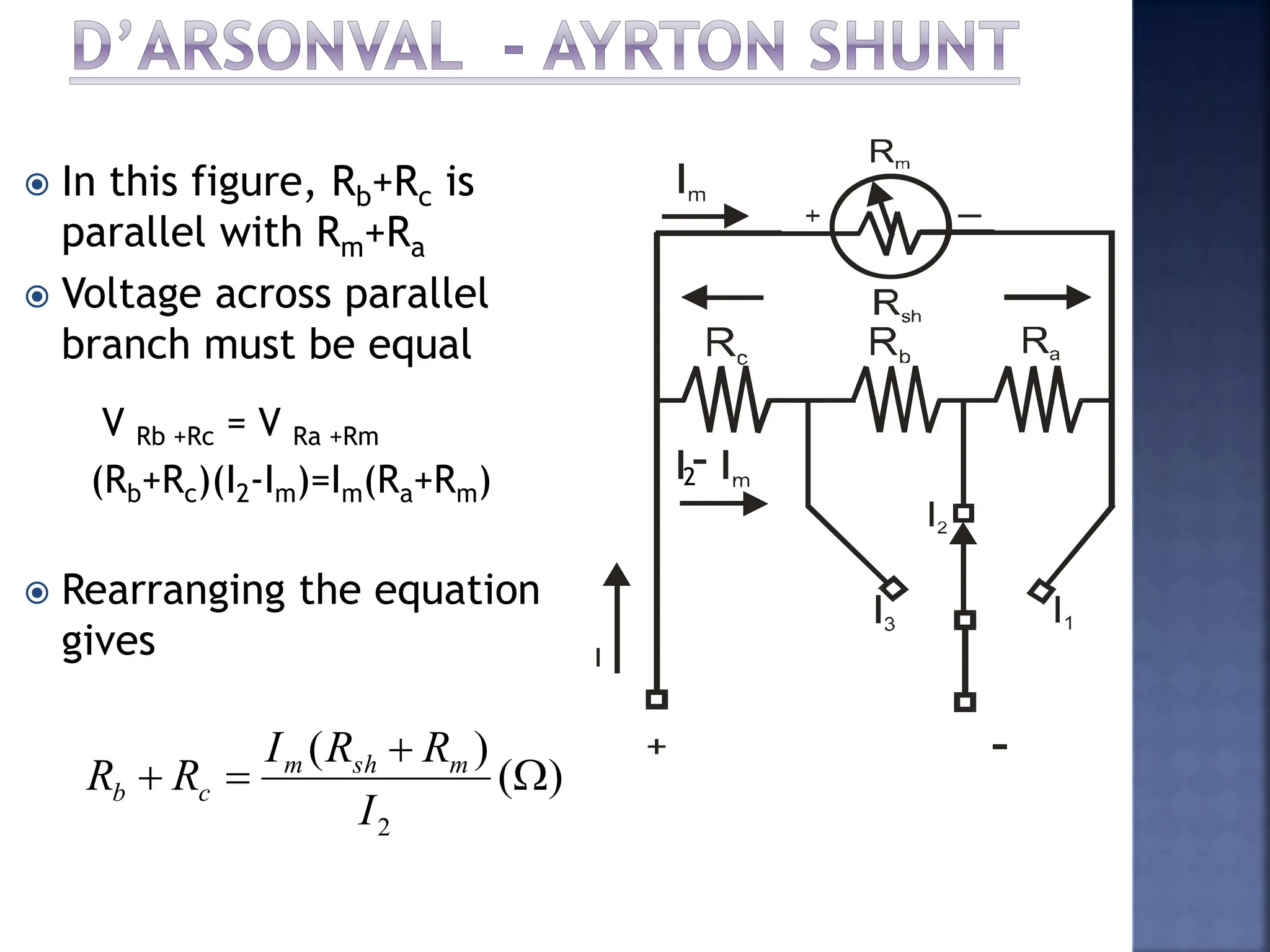
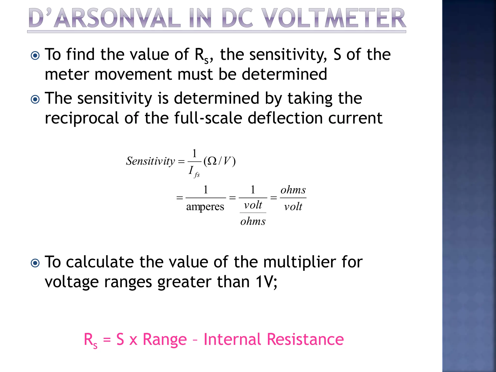
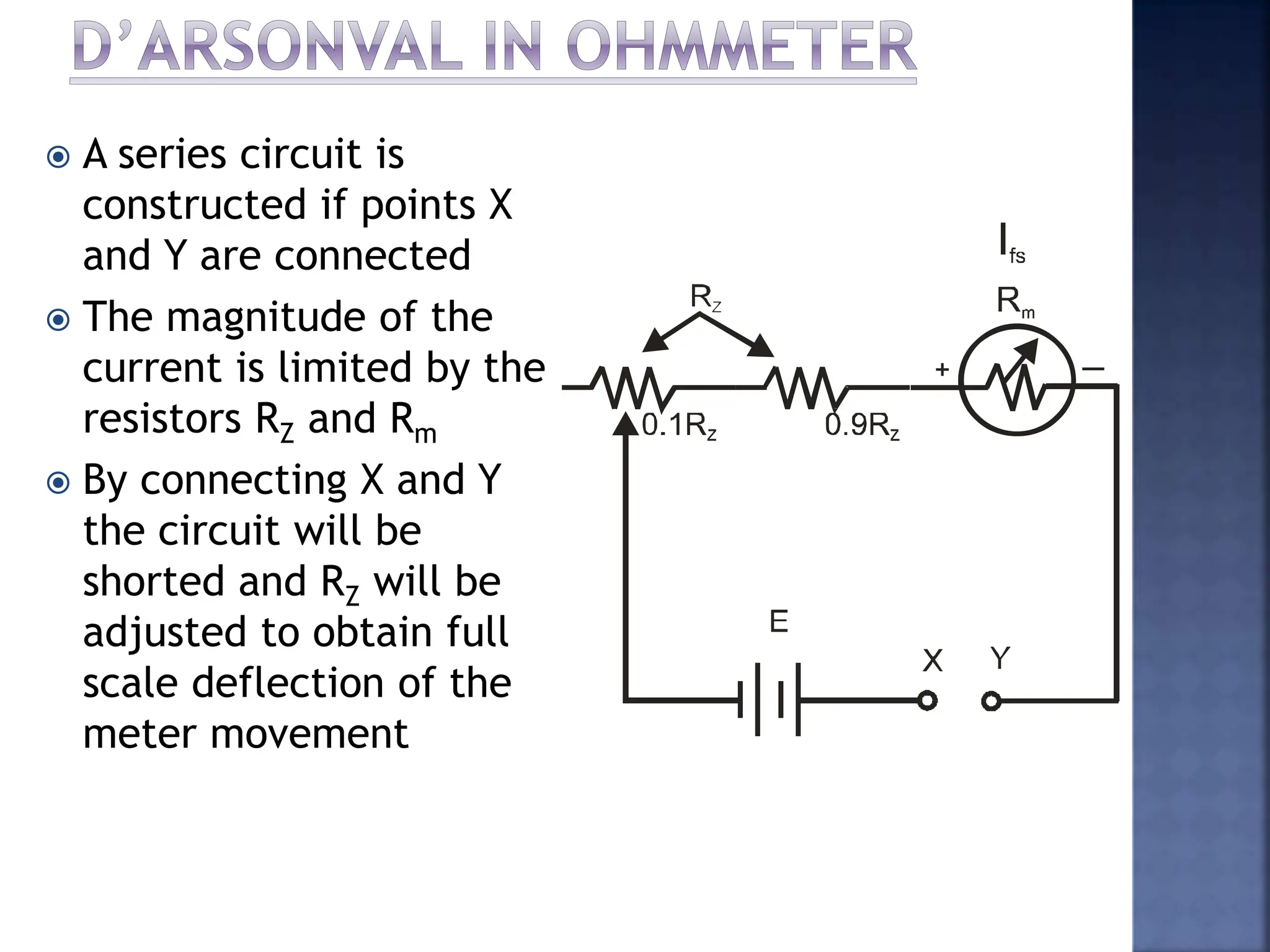
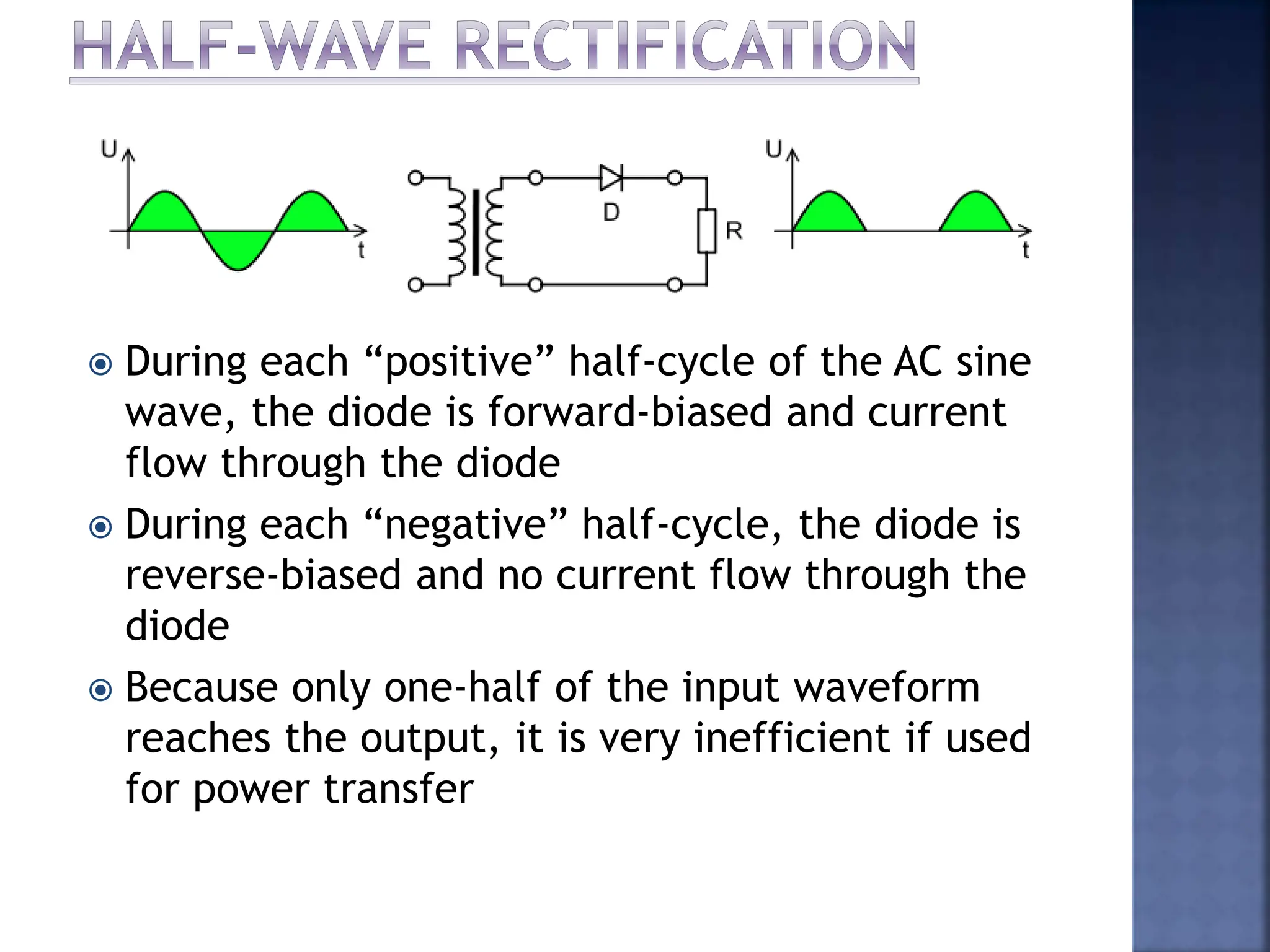
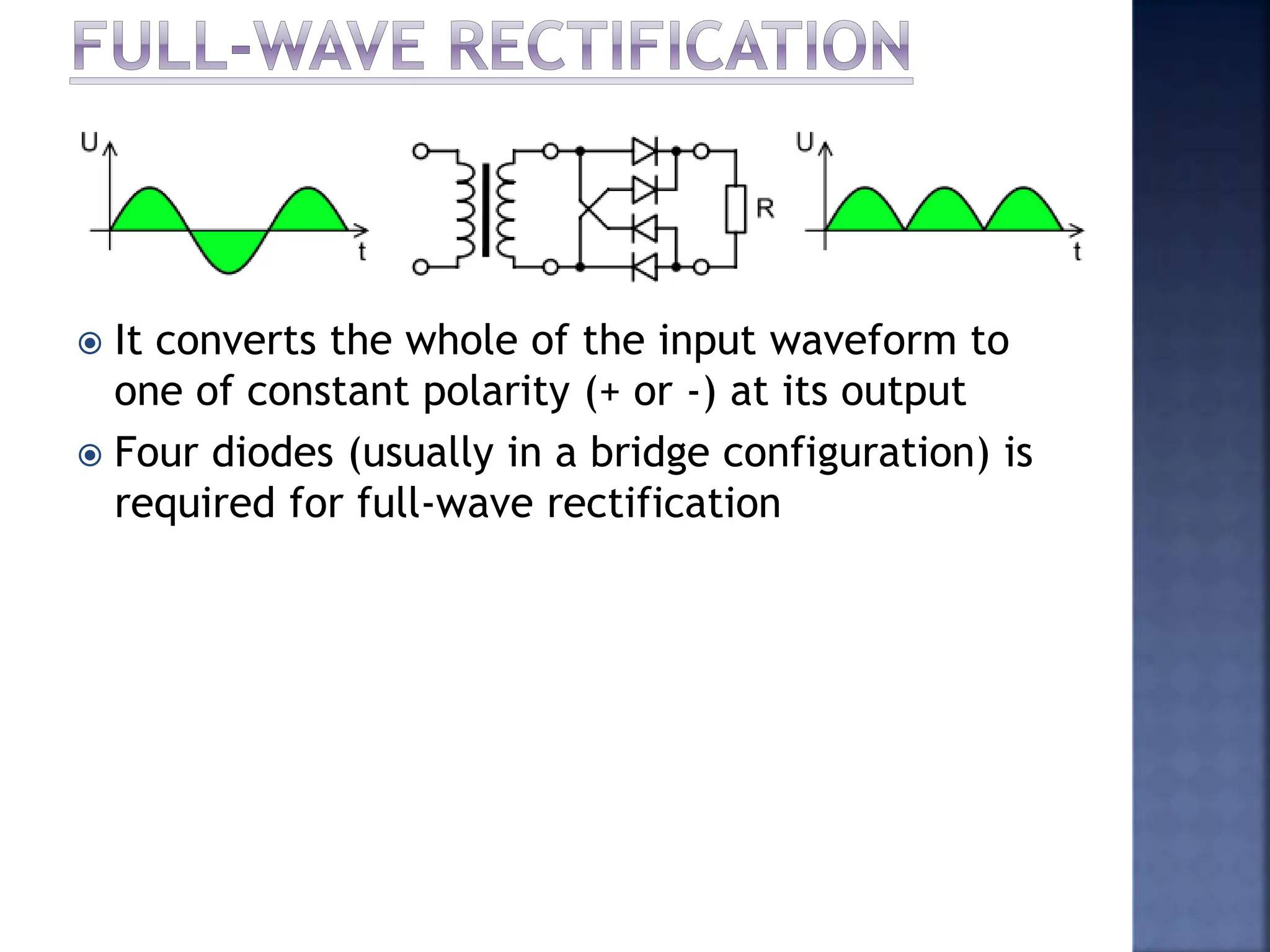
DC and AC meters
Hasmawati Antong
Lecturer
Department of Mechatronics Engineering
International Islamic University Malaysia
hasmawati@iium.edu.my
DC
METERS
 Introduction to meter
 Galvanometer
 Permanent-magnet moving coil
 D’Arsonval meter movement
 D’Arsonval in DC ammeter
 D’Arsonval – Ayrton Shunt
 D’Arsonval in DC voltmeter
 Voltmeter loading effect
 D’Arsonval in ohmmeter
 Multiple range ohmmeter
 A meter is any device built to accurately
detect and display an electrical quantity in a
form readable by a human being
 Usually this “readable form” is visual:
- motion of a pointer on a scale
- a series of lights arranged to form a
“bargraph”
- a display composed of numerical figures
 In the analysis and testing of circuits, there
are meters designed to accurately measure
voltage, current and resistance.
AC voltage
Current
Resistance
DC voltage
 Most modern meters are DIGITAL  their
readable display is in the form of numerical
digits
 Older designs of meters uses a pointer device
to display the quantity being measured
 In either case, the principle adopted for the
display mechanism are the same
 The display mechanism of meter is called
meter movement
 The first meter movement were known as
GALVANOMETERS
 A simple galvanometer is
made from a magnetized
needle suspended from a
string and positioned within
a coil of wire
 Current through the wire coil
produces magnetic field
which deflects the needle
from pointing in the direction
of earth’s magnetic field
 Nowadays, the term galvanometer usually refers to
any design of electromagnetic meter movement
built such as permanent-magnet moving coil (PMMC)
 PMMC is a practical electromagnetic meter
made with a pivoting wire coil suspended in
a strong magnetic field and shielded from
the majority of outside influences
Horseshoe magnet
Pointer
Zero position control
Control spring
Counter weight
Pole shoe
Coil
Working Principle
 Current to be measured is directed through the
coils of the electromagnet
 Magnetic field produced by the current opposed
the field of the permanent magnet and causes
rotation of the magnet core
 The core is restrained by springs so that the
needle will move in proportion to the current
intensity
 The more current applied to the core, the
stronger the opposing field, and the larger the
needle deflection
 When the current is stopped, the opposing field
collapsed and the needle return to zero
 The arc on the meter
display is labeled
with numbers to
indicate the value of
the quantity being
measured
 An increased in
measured current drives the
needle to the right
 A decrease in measured current causes the needle to
drop back to its resting position on the left
 Most meter movements are polarity-sensitive  one
direction of current drive the needle to the right and
the other driving it to the left
 Common polarity-sensitive movements include the
D’Arsonval design, which is a PMMC-type instrument.
 Current in one direction through the wire will produce
a clockwise torque on
the needle mechanism
 Current in the other
direction will produce a
counter-clockwise
torque
 D’Arsonval meter
movement is a current
responding device regardless the units (volts, ohms…)
for which the scale is calibrated
 Limitation  measure current less than 1mA
 A modification is needed to increase the range of
current that can be measured by the basic meter
movement
 A low resistance, shunt resistance (Rsh) is placed
parallel to the meter movement resistance, Rm
 Rsh will provide an alternate path for the total
metered current around the meter movement
 In most circuit,
Ish > Im
Rsh = shunt resistance
Rm = internal resistance of
the meter movement
(R of the moving
coil)
Ish = current through the
shunt
Im = full scale deflection
current of the meter
movement
I = full scale deflection
current for the
ammeter
D’Arsonval meter
movement used in an
ammeter circuit
 Voltage drop across the meter movement is
 The voltage drop across the shunt and meter
movement is the same.
 The current through the shunt is
 Therefor Rsh is
m
m
m R
I
V 
m
sh V
V 
m
sh I
I
I 

)
(
R
I
I
I
R
I
I
I
R
I
I
V
R m
m
m
m
sh
m
sh
m
m
sh
sh
sh 






Example 1:
Calculate the value of the shunt resistance required
to convert a 1mA meter movement, with a 100Ω
internal resistance into a 0 to 10mA ammeter
 The purpose of the shunt circuit is to measure
current, I that is n-time multiple of Im
 The number n is called the multiplying factor
and related I and Im as
I=nIm
1
-
n
R
I
nI
R
I
R
m
m
m
m
m
sh



Example 2:
A 100μA meter movement with an internal
resistance of 800Ω is used in a 0 to 100mA
ammeter. Find the value of the multiplying
factor and the required shunt
resistance.
 Limitation  only works well on a single-
range ammeter
 To overcome this limitation, Ayrton shunt is
introduced
 More suitable design for a
multiple-range ammeter
 Also, it can be used with a
wide range of meter
movements
 The individual resistance
value of the shunts are
calculated by starting with
the most sensitive range
towards the least sensitive
range
 In this figure, the most sensitive
range is the 1A range
 The least sensitive range is the
10A range
 When the meter is connected to
the most sensitive range, total
shunt resistance is
 Rsh can also be calculated using
Rsh = Ra + Rb + Rc
1
n
R
R m
sh


* In this case, I is equal to 1A
*
 In this figure, Rb+Rc is
parallel with Rm+Ra
 Voltage across parallel
branch must be equal
 Rearranging the equation
gives
V Rb +Rc = V Ra +Rm
(Rb+Rc)(I2-Im)=Im(Ra+Rm) 2
)
(
)
(
2




I
R
R
I
R
R m
sh
m
c
b
2
)
(
)
( 


 c
b
sh
a R
R
R
R
)
(
)
(
3



I
R
R
I
R m
sh
m
c
)
(

 a
sh
b R
R
R
Example 3:
Compute the value of the shunt resistors for the
circuit shown below
 The basic D’Arsonval meter movement can be
converted to a DC voltmeter by connecting a
multiplier in series with the meter movement
 Rs extends the voltage range and limit current
through D’Arsonval meter movement to a
maximum full scale deflection
Rs
 To find the value of Rs, the sensitivity, S of the
meter movement must be determined
 The sensitivity is determined by taking the
reciprocal of the full-scale deflection current
 To calculate the value of the multiplier for
voltage ranges greater than 1V;
volt
ohms
ohms
volt
V
I
y
Sensitivit
fs





1
amperes
1
)
/
(
1
Rs = S x Range – Internal Resistance
Example 4:
Calculate the sensitivity of a 100μA meter
movement which is to be used as a DC voltmeter
Example 5:
Calculate the value of the multiplier resistance
on the 50V range of a dc voltmeter that used a
500μA meter movement with an internal r
esistance of 1kΩ
Example 6:
Calculate the value of the multiplier resistance
for the multiple ranges DC voltmeter circuit
Example 7:
Calculate the value of the multiplier resistor for
the multiple range DC voltmeter circuit shown
 When a voltmeter is used to measure the voltage
across a circuit component, the circuit itself is
parallel with the circuit component in the
voltmeter
 The combination of two parallel resistors is less
than any of the two resistor value.
 Therefore:
- The voltage across the component is less when
the voltmeter is connected
- The decrease of voltage is known as voltmeter
loading
- The resulting error is known as loading error
Example 8:
Two different voltmeter
is used to measure the
voltage across resistor RB
in the figure. Calculate:
(a) VRB without meter connected
(b) VRB when meter A is used
(c) VRB when meter B is used
(d) Error in voltmeter reading
Meter A: S=1kΩ/V, Rm=0.2k Ω,
range=10V
Meter B: S=20kΩ/V, Rm=1.5k Ω,
range=10V
Example 9:
Find the voltage reading and
the percentage of error of
each reading obtained with a
voltmeter on
(a) Its 3V range
(b) Its 10V range
(c) Its 30V range
When connected across RB.
Instrument has 20kΩ/V
sensitivity
 A series circuit is
constructed if points X
and Y are connected
 The magnitude of the
current is limited by the
resistors RZ and Rm
 By connecting X and Y
the circuit will be
shorted and RZ will be
adjusted to obtain full
scale deflection of the
meter movement
 The amplitude of the
current through the
meter movement can be
determined as
 When measuring
unknown resistor, RX the
circuit current will be
m
z
f s
R
R
E
I


x
m
z R
R
R
E
I



 The amplitude of the
current through the
meter movement can be
determined as
 When measuring
unknown resistor, RX the
circuit current will be
m
z
f s
R
R
E
I


x
m
z R
R
R
E
I



* Current I is less than Ifs because of the additional resistance RX
 The ratio of the full-scale deflection current Ifs is
equal to the ratio of the circuit resistance and may
be expressed as
x
m
z
m
z
m
z
x
m
z
fs R
R
R
R
R
)
R
R
/(
E
)
R
R
R
/(
E
I
I
P









Example 10:
An ohmmeter uses a 1.5V battery and a basic 50μA
movement. The internal resistance is 1kΩ. Calculate
(a) The value of Rz required
(b) The value of Rx that would cause half-scale
deflection in the circuit
Example 11:
An ohmmeter is designed around a 1mA meter
movement and a 1.5V call. If the cell voltage decays to
1.3V because of aging, calculate the resulting error at
midrange on the ohmmeter scale
 Ohmmeters are usually nonlinear due to,
 to high internal resistance
 however, at half scale the value of Rx is equal to
the total internal resistance, Rm of an ohmmeter
 A variable resistor may be applied to the ohmmeter
probes and set the value required for half-scale
deflection of the pointer in order to mark the scale.
AC
METERS
 AC meters
 Half-wave rectification
 Full-wave rectification
 Electrodynamometer
 Use to measure AC current or voltage
 By far, the widely used meter movement is the
D’Arsonval meter movement
 However, it cannot measure AC current or
voltage directly
 Some modification is required to use the
D’Arsonval meter movement with AC meter:
1) Half-wave rectification
2) Full-wave rectification
 A rectifier is a circuit which converts AC input to
DC output
 During each “positive” half-cycle of the AC sine
wave, the diode is forward-biased and current
flow through the diode
 During each “negative” half-cycle, the diode is
reverse-biased and no current flow through the
diode
 Because only one-half of the input waveform
reaches the output, it is very inefficient if used
for power transfer
 It converts the whole of the input waveform to
one of constant polarity (+ or -) at its output
 Four diodes (usually in a bridge configuration) is
required for full-wave rectification
 A type of AC meter
 It is a current sensitive device
 Able to handle more current than the
D’Arsonval meter movement could handle
without shunt
 A single coil movement could be used to
measure DC / AC current or voltage
 It consists of a fixed coil that is divided into two
equal halves, separated by a movable coil
 It has a very low sensitivity (approximately 20 –
100Ω/V)
Example 12:
An electrodynamometer movement that has a
full-scale deflection current rating of 10mA is
to be used in a voltmeter circuit. Calculate the
value of the multiplier for a 10V range if
Rm=50Ω
Example 13:
An electrodynamometer movement with a full-
scale deflection current rating of 10mA is to be
used as a 1A ammeter. If the resistance of the
moving coil is 40Ω. What is the value of the
shunt?

05_DCAC_meter.pptx

  • 1.
    DC and ACmeters Hasmawati Antong Lecturer Department of Mechatronics Engineering International Islamic University Malaysia hasmawati@iium.edu.my
  • 2.
  • 3.
     Introduction tometer  Galvanometer  Permanent-magnet moving coil  D’Arsonval meter movement  D’Arsonval in DC ammeter  D’Arsonval – Ayrton Shunt  D’Arsonval in DC voltmeter  Voltmeter loading effect  D’Arsonval in ohmmeter  Multiple range ohmmeter
  • 4.
     A meteris any device built to accurately detect and display an electrical quantity in a form readable by a human being  Usually this “readable form” is visual: - motion of a pointer on a scale - a series of lights arranged to form a “bargraph” - a display composed of numerical figures  In the analysis and testing of circuits, there are meters designed to accurately measure voltage, current and resistance.
  • 5.
  • 6.
     Most modernmeters are DIGITAL  their readable display is in the form of numerical digits  Older designs of meters uses a pointer device to display the quantity being measured  In either case, the principle adopted for the display mechanism are the same  The display mechanism of meter is called meter movement  The first meter movement were known as GALVANOMETERS
  • 7.
     A simplegalvanometer is made from a magnetized needle suspended from a string and positioned within a coil of wire  Current through the wire coil produces magnetic field which deflects the needle from pointing in the direction of earth’s magnetic field  Nowadays, the term galvanometer usually refers to any design of electromagnetic meter movement built such as permanent-magnet moving coil (PMMC)
  • 8.
     PMMC isa practical electromagnetic meter made with a pivoting wire coil suspended in a strong magnetic field and shielded from the majority of outside influences Horseshoe magnet Pointer Zero position control Control spring Counter weight Pole shoe Coil
  • 9.
    Working Principle  Currentto be measured is directed through the coils of the electromagnet  Magnetic field produced by the current opposed the field of the permanent magnet and causes rotation of the magnet core  The core is restrained by springs so that the needle will move in proportion to the current intensity  The more current applied to the core, the stronger the opposing field, and the larger the needle deflection  When the current is stopped, the opposing field collapsed and the needle return to zero
  • 10.
     The arcon the meter display is labeled with numbers to indicate the value of the quantity being measured  An increased in measured current drives the needle to the right  A decrease in measured current causes the needle to drop back to its resting position on the left  Most meter movements are polarity-sensitive  one direction of current drive the needle to the right and the other driving it to the left
  • 11.
     Common polarity-sensitivemovements include the D’Arsonval design, which is a PMMC-type instrument.  Current in one direction through the wire will produce a clockwise torque on the needle mechanism  Current in the other direction will produce a counter-clockwise torque  D’Arsonval meter movement is a current responding device regardless the units (volts, ohms…) for which the scale is calibrated  Limitation  measure current less than 1mA
  • 12.
     A modificationis needed to increase the range of current that can be measured by the basic meter movement  A low resistance, shunt resistance (Rsh) is placed parallel to the meter movement resistance, Rm  Rsh will provide an alternate path for the total metered current around the meter movement  In most circuit, Ish > Im
  • 13.
    Rsh = shuntresistance Rm = internal resistance of the meter movement (R of the moving coil) Ish = current through the shunt Im = full scale deflection current of the meter movement I = full scale deflection current for the ammeter D’Arsonval meter movement used in an ammeter circuit
  • 14.
     Voltage dropacross the meter movement is  The voltage drop across the shunt and meter movement is the same.  The current through the shunt is  Therefor Rsh is m m m R I V  m sh V V  m sh I I I   ) ( R I I I R I I I R I I V R m m m m sh m sh m m sh sh sh       
  • 15.
    Example 1: Calculate thevalue of the shunt resistance required to convert a 1mA meter movement, with a 100Ω internal resistance into a 0 to 10mA ammeter
  • 16.
     The purposeof the shunt circuit is to measure current, I that is n-time multiple of Im  The number n is called the multiplying factor and related I and Im as I=nIm 1 - n R I nI R I R m m m m m sh   
  • 17.
    Example 2: A 100μAmeter movement with an internal resistance of 800Ω is used in a 0 to 100mA ammeter. Find the value of the multiplying factor and the required shunt resistance.
  • 18.
     Limitation only works well on a single- range ammeter  To overcome this limitation, Ayrton shunt is introduced
  • 19.
     More suitabledesign for a multiple-range ammeter  Also, it can be used with a wide range of meter movements  The individual resistance value of the shunts are calculated by starting with the most sensitive range towards the least sensitive range
  • 20.
     In thisfigure, the most sensitive range is the 1A range  The least sensitive range is the 10A range  When the meter is connected to the most sensitive range, total shunt resistance is  Rsh can also be calculated using Rsh = Ra + Rb + Rc 1 n R R m sh   * In this case, I is equal to 1A *
  • 21.
     In thisfigure, Rb+Rc is parallel with Rm+Ra  Voltage across parallel branch must be equal  Rearranging the equation gives V Rb +Rc = V Ra +Rm (Rb+Rc)(I2-Im)=Im(Ra+Rm) 2 ) ( ) ( 2     I R R I R R m sh m c b
  • 22.
    2 ) ( ) (     c b sh aR R R R ) ( ) ( 3    I R R I R m sh m c ) (   a sh b R R R
  • 23.
    Example 3: Compute thevalue of the shunt resistors for the circuit shown below
  • 24.
     The basicD’Arsonval meter movement can be converted to a DC voltmeter by connecting a multiplier in series with the meter movement  Rs extends the voltage range and limit current through D’Arsonval meter movement to a maximum full scale deflection Rs
  • 25.
     To findthe value of Rs, the sensitivity, S of the meter movement must be determined  The sensitivity is determined by taking the reciprocal of the full-scale deflection current  To calculate the value of the multiplier for voltage ranges greater than 1V; volt ohms ohms volt V I y Sensitivit fs      1 amperes 1 ) / ( 1 Rs = S x Range – Internal Resistance
  • 26.
    Example 4: Calculate thesensitivity of a 100μA meter movement which is to be used as a DC voltmeter
  • 27.
    Example 5: Calculate thevalue of the multiplier resistance on the 50V range of a dc voltmeter that used a 500μA meter movement with an internal r esistance of 1kΩ
  • 28.
    Example 6: Calculate thevalue of the multiplier resistance for the multiple ranges DC voltmeter circuit
  • 29.
    Example 7: Calculate thevalue of the multiplier resistor for the multiple range DC voltmeter circuit shown
  • 30.
     When avoltmeter is used to measure the voltage across a circuit component, the circuit itself is parallel with the circuit component in the voltmeter  The combination of two parallel resistors is less than any of the two resistor value.  Therefore: - The voltage across the component is less when the voltmeter is connected - The decrease of voltage is known as voltmeter loading - The resulting error is known as loading error
  • 31.
    Example 8: Two differentvoltmeter is used to measure the voltage across resistor RB in the figure. Calculate: (a) VRB without meter connected (b) VRB when meter A is used (c) VRB when meter B is used (d) Error in voltmeter reading Meter A: S=1kΩ/V, Rm=0.2k Ω, range=10V Meter B: S=20kΩ/V, Rm=1.5k Ω, range=10V
  • 32.
    Example 9: Find thevoltage reading and the percentage of error of each reading obtained with a voltmeter on (a) Its 3V range (b) Its 10V range (c) Its 30V range When connected across RB. Instrument has 20kΩ/V sensitivity
  • 33.
     A seriescircuit is constructed if points X and Y are connected  The magnitude of the current is limited by the resistors RZ and Rm  By connecting X and Y the circuit will be shorted and RZ will be adjusted to obtain full scale deflection of the meter movement
  • 34.
     The amplitudeof the current through the meter movement can be determined as  When measuring unknown resistor, RX the circuit current will be m z f s R R E I   x m z R R R E I   
  • 35.
     The amplitudeof the current through the meter movement can be determined as  When measuring unknown resistor, RX the circuit current will be m z f s R R E I   x m z R R R E I    * Current I is less than Ifs because of the additional resistance RX
  • 36.
     The ratioof the full-scale deflection current Ifs is equal to the ratio of the circuit resistance and may be expressed as x m z m z m z x m z fs R R R R R ) R R /( E ) R R R /( E I I P         
  • 37.
    Example 10: An ohmmeteruses a 1.5V battery and a basic 50μA movement. The internal resistance is 1kΩ. Calculate (a) The value of Rz required (b) The value of Rx that would cause half-scale deflection in the circuit
  • 38.
    Example 11: An ohmmeteris designed around a 1mA meter movement and a 1.5V call. If the cell voltage decays to 1.3V because of aging, calculate the resulting error at midrange on the ohmmeter scale
  • 39.
     Ohmmeters areusually nonlinear due to,  to high internal resistance  however, at half scale the value of Rx is equal to the total internal resistance, Rm of an ohmmeter  A variable resistor may be applied to the ohmmeter probes and set the value required for half-scale deflection of the pointer in order to mark the scale.
  • 41.
  • 42.
     AC meters Half-wave rectification  Full-wave rectification  Electrodynamometer
  • 43.
     Use tomeasure AC current or voltage  By far, the widely used meter movement is the D’Arsonval meter movement  However, it cannot measure AC current or voltage directly  Some modification is required to use the D’Arsonval meter movement with AC meter: 1) Half-wave rectification 2) Full-wave rectification  A rectifier is a circuit which converts AC input to DC output
  • 44.
     During each“positive” half-cycle of the AC sine wave, the diode is forward-biased and current flow through the diode  During each “negative” half-cycle, the diode is reverse-biased and no current flow through the diode  Because only one-half of the input waveform reaches the output, it is very inefficient if used for power transfer
  • 45.
     It convertsthe whole of the input waveform to one of constant polarity (+ or -) at its output  Four diodes (usually in a bridge configuration) is required for full-wave rectification
  • 46.
     A typeof AC meter  It is a current sensitive device  Able to handle more current than the D’Arsonval meter movement could handle without shunt  A single coil movement could be used to measure DC / AC current or voltage
  • 47.
     It consistsof a fixed coil that is divided into two equal halves, separated by a movable coil  It has a very low sensitivity (approximately 20 – 100Ω/V)
  • 48.
    Example 12: An electrodynamometermovement that has a full-scale deflection current rating of 10mA is to be used in a voltmeter circuit. Calculate the value of the multiplier for a 10V range if Rm=50Ω
  • 49.
    Example 13: An electrodynamometermovement with a full- scale deflection current rating of 10mA is to be used as a 1A ammeter. If the resistance of the moving coil is 40Ω. What is the value of the shunt?